Incorrect gas gauge reading
 01-07-2016, 10:31 AM
#1

I have seen plenty of information on repairing (cleaning) the fuel sending unit in the coupes that show incorrect reading for the gas gauge, but not much information on how to remove the sending units and cleaning them for the convertibles. When I closed my top the other day, it looked to me like the fuel tank was beneath the vinyl cover where the roof is stored when its open. It may be as easy as removing the vinyl cover and unbolting the two sending units. Is this true?
 01-11-2016, 11:44 AM
#3
I decided to jump in and figure out the fuel gauge issue. I figured the gas tank would be accessible under the storage area for the convertible top. It is not. There is a metal casing under the vinyl cover.
Basically, the gas tank is accessed the same as the coupe, except, with the top down, there is more light to see what you are doing. I decided to do a write up anyway since this is a common problem in the Z and it is not too difficult to fix.
Tools needed:
8mm wrench
10mm socket and ratchet
Phillips and flat blade screw driver
rags
Q tips
electronic cleaner or alcohol
Procedure:
First, put the top down for more light and room. Then move both seats forward. Disconnect the battery.
Starting with the drivers side, pry the top of the bass speaker surround from the top and pivot it forward and pull out:
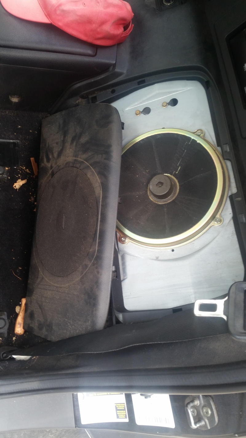
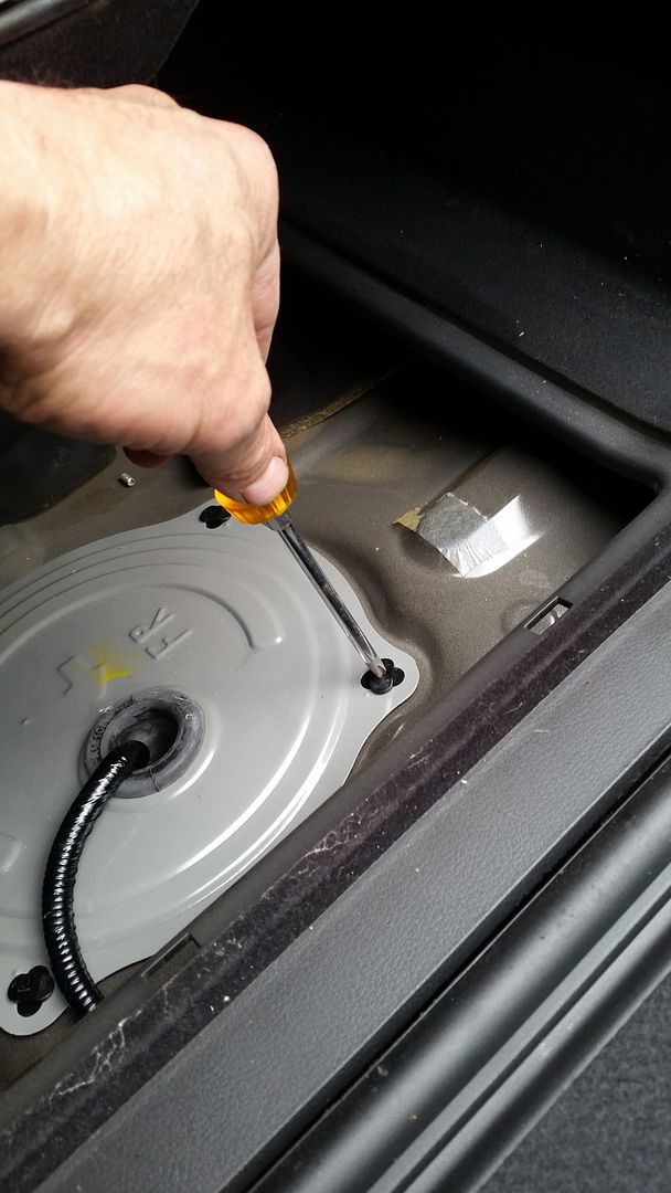
Remove four bolts holding in the bass speaker with 10mm socket and ratchet and disconnect the speaker and set it aside. Push the insulation away from the access cover to the sending unit. You will see four black plastic fasteners. Use the Phillips screw driver and turn the fasteners 1/4 turn clockwise and remove the access cover.
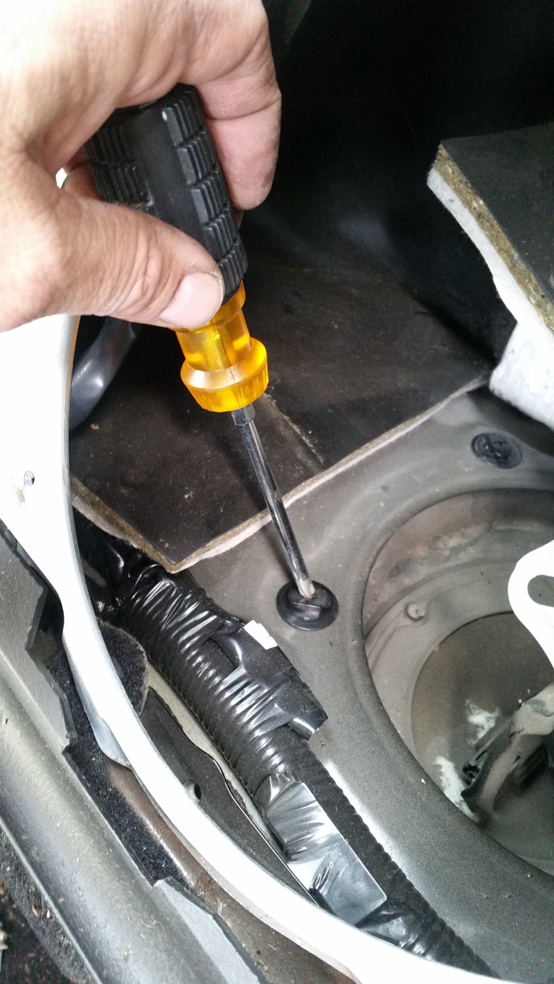
Now you will see the sending unit beneath a lot of dirt. Clean off the dirt with a damp rag. Why? Because if you don't, the dirt will pour into the tank when you remove the sending unit like it did for me, ok? Use the 8mm wrench and crack the six little bolts loose and use the Phillips screwdriver to unscrew the sending unit bolts. Place rags around the area of the sending unit as gas will spill. Lift off the black ring that is in top of the sending unit. Lift up the sending unit SLOWLY and maneuver the arm and float out of the tank as you lift the unit up. Wipe off any gas that spills on the blue O ring.
Take sending unit over to a work bench.
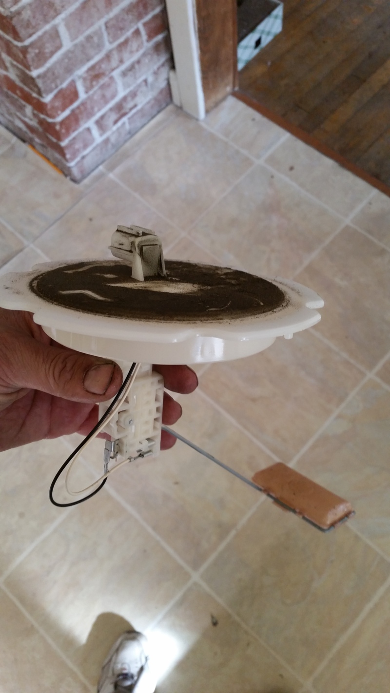
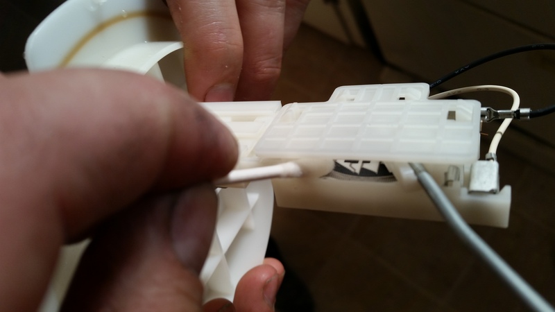
The float arm has a metal tab that rubs on a variable resistor strip which feeds voltage to the gas gauge. There are two lugs. Measure the resistance across the lugs as you slowly move the float up and down. The range of resistance should be about 5 ohms - 45 ohms, up to down. Use a q tip dipped in alcohol, clean the resistor strip. Also, spray some electrical cleaner in there and move the float up and down.
Once you are confident that the resistor is clean, install the sending unit in the same way as when you pulled it out. Installation is the reverse of the removal.
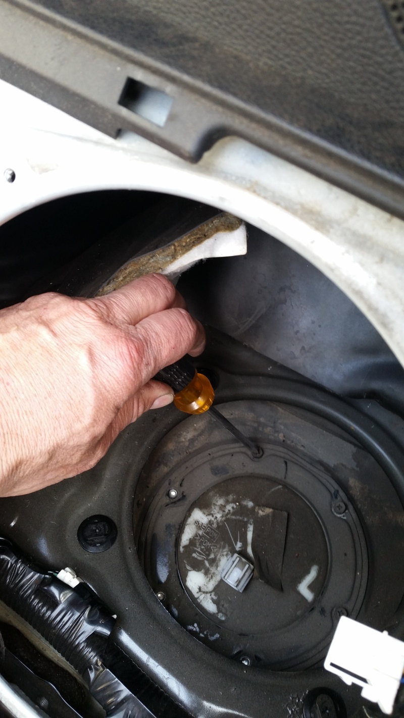
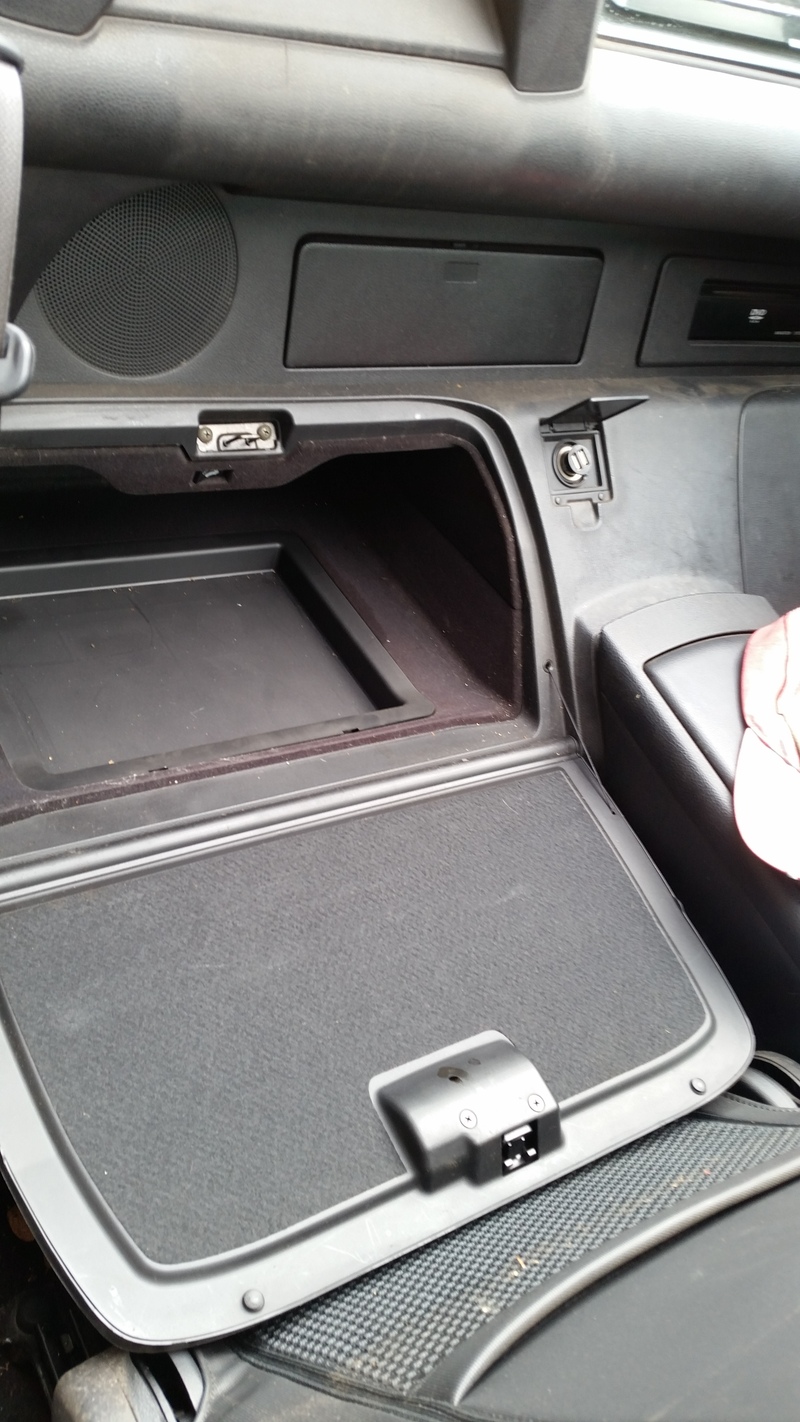
The passenger side sending unit is easier to get to, but harder to pull out. Open the glove compartment/cubby hole and remove the false floor.
Remove the plastic floor you see in the picture above to reveal the sending unit.
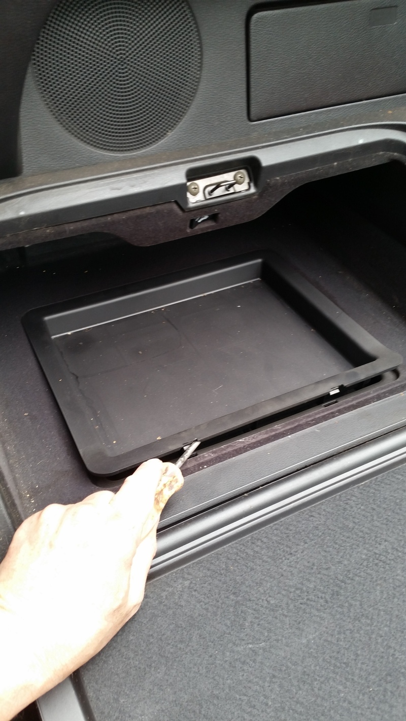
Turn the four access cover fasteners 1/4 turn clockwise.
With the cover off, this is what you see:
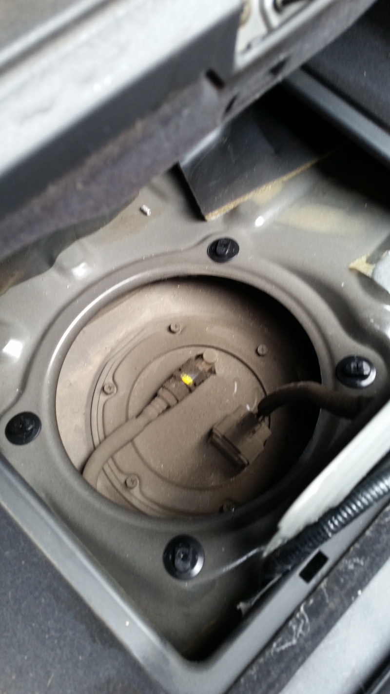
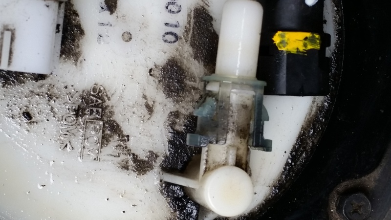
Clean off the top of the sending unit with a damp rag. Using your flat blade screwdriver, remove the wire harness connector. Then pinch the fuel hose connector and remove the fuel hose:
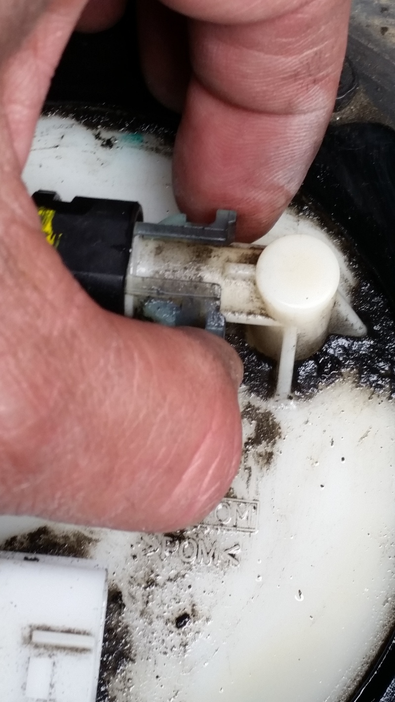
Fuel hose off:
This part is tricky. The fuel pump and sending unit are all together, so its much larger than the drivers side. Also, the fuel pump is on springs and squishes down. Pull out the sending unit/fuel pump about halfway. On the backside is a black hose that is hard to remove. Here are two pictures:
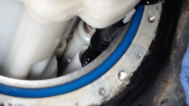
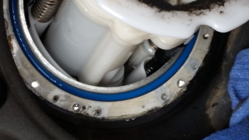
You can see the springs and the blue O ring also. Make sure the O ring is wiped clean of gas and dirt. Make sure you have rags around the area. Pull out the unit and take it to your work bench.
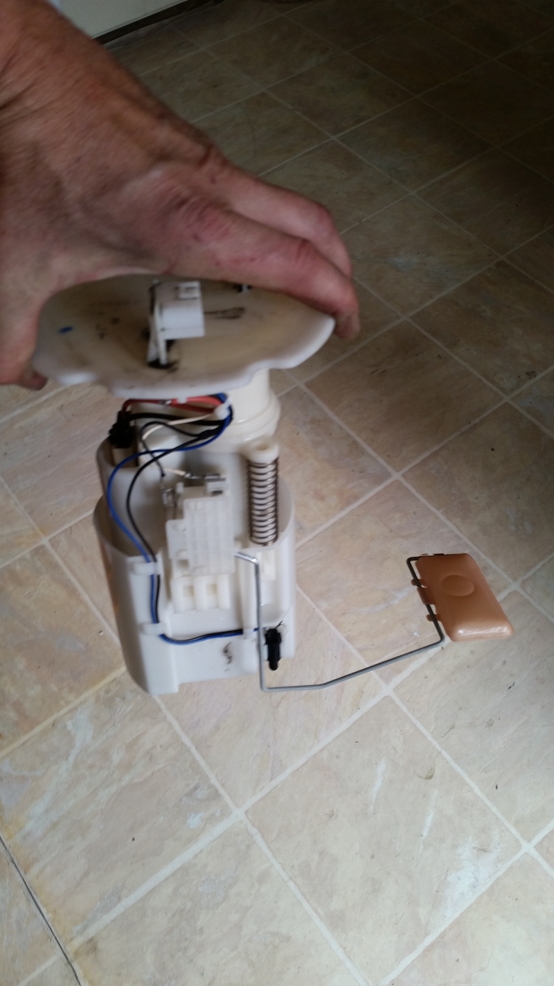
Clean the sending unit strip like you did the other one. Measure the resistance as you move the float slowly up and down. It should read smooth and linear. I think this one measures 82 ohms on the bottom and 5 ohm when the float was raised.
Installation is the reverse of removal. The result is a working gauge.
The edge of the access holes are VERY sharp. If you dont believe me, then look at this:

Its nice to have a functioning gas gauge!!
Basically, the gas tank is accessed the same as the coupe, except, with the top down, there is more light to see what you are doing. I decided to do a write up anyway since this is a common problem in the Z and it is not too difficult to fix.
Tools needed:
8mm wrench
10mm socket and ratchet
Phillips and flat blade screw driver
rags
Q tips
electronic cleaner or alcohol
Procedure:
First, put the top down for more light and room. Then move both seats forward. Disconnect the battery.
Starting with the drivers side, pry the top of the bass speaker surround from the top and pivot it forward and pull out:

Remove four bolts holding in the bass speaker with 10mm socket and ratchet and disconnect the speaker and set it aside. Push the insulation away from the access cover to the sending unit. You will see four black plastic fasteners. Use the Phillips screw driver and turn the fasteners 1/4 turn clockwise and remove the access cover.

Now you will see the sending unit beneath a lot of dirt. Clean off the dirt with a damp rag. Why? Because if you don't, the dirt will pour into the tank when you remove the sending unit like it did for me, ok? Use the 8mm wrench and crack the six little bolts loose and use the Phillips screwdriver to unscrew the sending unit bolts. Place rags around the area of the sending unit as gas will spill. Lift off the black ring that is in top of the sending unit. Lift up the sending unit SLOWLY and maneuver the arm and float out of the tank as you lift the unit up. Wipe off any gas that spills on the blue O ring.

Take sending unit over to a work bench.

The float arm has a metal tab that rubs on a variable resistor strip which feeds voltage to the gas gauge. There are two lugs. Measure the resistance across the lugs as you slowly move the float up and down. The range of resistance should be about 5 ohms - 45 ohms, up to down. Use a q tip dipped in alcohol, clean the resistor strip. Also, spray some electrical cleaner in there and move the float up and down.

Once you are confident that the resistor is clean, install the sending unit in the same way as when you pulled it out. Installation is the reverse of the removal.
The passenger side sending unit is easier to get to, but harder to pull out. Open the glove compartment/cubby hole and remove the false floor.

Remove the plastic floor you see in the picture above to reveal the sending unit.

Turn the four access cover fasteners 1/4 turn clockwise.

With the cover off, this is what you see:

Clean off the top of the sending unit with a damp rag. Using your flat blade screwdriver, remove the wire harness connector. Then pinch the fuel hose connector and remove the fuel hose:

Fuel hose off:

This part is tricky. The fuel pump and sending unit are all together, so its much larger than the drivers side. Also, the fuel pump is on springs and squishes down. Pull out the sending unit/fuel pump about halfway. On the backside is a black hose that is hard to remove. Here are two pictures:


You can see the springs and the blue O ring also. Make sure the O ring is wiped clean of gas and dirt. Make sure you have rags around the area. Pull out the unit and take it to your work bench.

Clean the sending unit strip like you did the other one. Measure the resistance as you move the float slowly up and down. It should read smooth and linear. I think this one measures 82 ohms on the bottom and 5 ohm when the float was raised.
Installation is the reverse of removal. The result is a working gauge.
The edge of the access holes are VERY sharp. If you dont believe me, then look at this:

Its nice to have a functioning gas gauge!!
01-11-2016, 11:49 AM
#4
General & Tech Moderator
MY350Z.COM
MY350Z.COM


Great write up and pics, Deuce! 
09-05-2016, 07:11 AM
#6
Senior Super Moderator
MY350Z.COM
MY350Z.COM
iTrader: (13)
Found this thread because I noticed my gauge fluctuating a lot during a drive yesterday. Great pics and DIY instructions, Deus.

Trending Topics


Thread
Thread Starter
Forum
Replies
Last Post