New SQ-oriented install coming soon, all components ordered!
 12-04-2007, 06:50 AM
#81
Registered User
iTrader: (7)

Join Date: Aug 2006
Location: NJ
Posts: 2,136
Likes: 0
Received 0 Likes
on
0 Posts
Originally Posted by Ge|atinousFury
My RCA run length has increased a bit but even so it's just going to be a ~4ft run between the H701 processor in the stock sub location across to the amps in the glove box.
I guess the final wire layout will be:
1. AiNet + Optical cable up the center console to the stock sub compartment
2. 2awg power cable + passenger side speaker wires down passenger side door sill
3. Driver side speaker wires down driver's side doorsill
I guess the final wire layout will be:
1. AiNet + Optical cable up the center console to the stock sub compartment
2. 2awg power cable + passenger side speaker wires down passenger side door sill
3. Driver side speaker wires down driver's side doorsill
 ).
).
 12-04-2007, 06:54 AM
#82
Registered User
Thread Starter
iTrader: (1)

Join Date: Sep 2005
Location: Alabama
Posts: 146
Likes: 0
Received 0 Likes
on
0 Posts
Originally Posted by StreetOC192
Sounds like a good plan to me......gotta love the "noise free" optical carriers!!! LOL (it's what I do for a living ).
).
12-09-2007, 01:39 PM
#83
Registered User
Thread Starter
iTrader: (1)
Join Date: Sep 2005
Location: Alabama
Posts: 146
Likes: 0
Received 0 Likes
on
0 Posts
For all of you who have installed Alpine IVA-W200's or IVA-W205's, will the predrilled holes in the factory mounting bracket allow the IVA-W205 to sit flush with the dash or will it protrude?
Just wondering if I'm going to have to drill my own mounting holes in the factory head unit bracket...
Just wondering if I'm going to have to drill my own mounting holes in the factory head unit bracket...
12-09-2007, 04:21 PM
#84
Registered User

Join Date: Aug 2007
Location: Charlotte
Posts: 652
Likes: 0
Received 0 Likes
on
0 Posts
i drilled some new holes to sink it back a little bit. otherwise it sticks out about a 1/4".
mock it up in the dash piece before you do anything though. you can test fit it in there and then its only a few screws to remove to take it back out . i could also only get 3 screws on each side to go back in the chasis on the alpine.
mock it up in the dash piece before you do anything though. you can test fit it in there and then its only a few screws to remove to take it back out
. i could also only get 3 screws on each side to go back in the chasis on the alpine.
12-09-2007, 06:00 PM
#85
Registered User
Thread Starter
iTrader: (1)
Join Date: Sep 2005
Location: Alabama
Posts: 146
Likes: 0
Received 0 Likes
on
0 Posts
Originally Posted by hoss4131
i drilled some new holes to sink it back a little bit. otherwise it sticks out about a 1/4".
mock it up in the dash piece before you do anything though. you can test fit it in there and then its only a few screws to remove to take it back out . i could also only get 3 screws on each side to go back in the chasis on the alpine.
mock it up in the dash piece before you do anything though. you can test fit it in there and then its only a few screws to remove to take it back out
. i could also only get 3 screws on each side to go back in the chasis on the alpine.Also, my Metra dash kit came with the trim piece with the middle part already cut out. I guess they all come like this now? I was under the impression that I would have to cut the middle of it out to make it a double-din trim piece. There are 2 plastic bracket type pieces in the Metra kit that look like screw hole adapters or something....one for each side of the head unit. Will I have to use those?
Last edited by Ge|atinousFury; 12-09-2007 at 06:08 PM.
12-09-2007, 06:01 PM
#86
Registered User
Thread Starter
iTrader: (1)
Join Date: Sep 2005
Location: Alabama
Posts: 146
Likes: 0
Received 0 Likes
on
0 Posts
Originally Posted by BlueBoxer
Man, your install looks more ane more like mine everyday. lol I spend a good day crouching in my hatch and then pulling the doors off to put on two layers of Raammat and ensolite. However, I really love the improvements the deadening and pods made. Just be careful when you run the wires for your rears or to the sub in the hatch. I have one wire that I didn't secure very well and there is now a rattling that has me tempted to empty 6 magazines of .40 cal into it at times. I am still loving the Polks.
12-09-2007, 09:38 PM
#87
Registered User
iTrader: (13)

Join Date: Feb 2006
Location: Arizona
Posts: 1,390
Likes: 0
Received 0 Likes
on
0 Posts
If you rip off the rear panels you will see the spot where the power outlet is located. Directly behind that I had some speaker wires running up through it. I am not sure if I just failed to secure everything well the first time or not so I just matted the whole area like a freak on speed (overkill in other words). Definately predrill the mounting holes, mine stuck out initially and my A.D.D. came out big time until I could get it flush.
12-10-2007, 05:01 AM
#89
Registered User
Thread Starter
iTrader: (1)
Join Date: Sep 2005
Location: Alabama
Posts: 146
Likes: 0
Received 0 Likes
on
0 Posts
Originally Posted by BabyZiLLa
Any chance of getting some pics of your amp/processor rack when its in the cubby?
Great project btw.
Great project btw.
12-10-2007, 06:36 AM
#90
Registered User
iTrader: (7)

Join Date: Jan 2007
Location: Canada
Posts: 930
Likes: 0
Received 0 Likes
on
0 Posts
Originally Posted by Ge|atinousFury
Thanks. Actually I just got the driver's side rack installed late last week (as a test fit only to drive around a bit and see how it does when mounted) so I can snap some pics tonight probably.
Keep the pics coming of the entire project. Will make for a good thread.
12-13-2007, 04:26 PM
#91
Registered User
Thread Starter
iTrader: (1)
Join Date: Sep 2005
Location: Alabama
Posts: 146
Likes: 0
Received 0 Likes
on
0 Posts
I haven't forgotten about the pictures....just been short on time lately.
The latest update is that I went ahead and installed the master ground lug in the stock sub compartment and ran 2 4awg ground wires over to the glove box for the 2 PDX amps. The master ground lug had a big star washer and I cranked the nut on it down good so I'm sure I have a nice physical ground connection. I also took the wiring harness for the W205 and extended the ground wire by about 10 inches to make sure it would have some slack when grounded.
At this point the only parts I have yet to receive are the kicks from Bing, and I hope to receive those sometime during Christmas break if the stock kick panels get shipped to him in time (I had them drop shipped to Bing from Performance Nissan and the dealer had to order them from the warehouse first...should be shipping them to him any day now).
Last edited by Ge|atinousFury; 12-13-2007 at 04:30 PM.
12-18-2007, 05:17 AM
#93
Registered User
Thread Starter
iTrader: (1)
Join Date: Sep 2005
Location: Alabama
Posts: 146
Likes: 0
Received 0 Likes
on
0 Posts
Originally Posted by BabyZiLLa
Do i have to make paypal donations to get these pics or what? 
12-18-2007, 07:08 AM
#94
Registered User
iTrader: (7)
Join Date: Jan 2007
Location: Canada
Posts: 930
Likes: 0
Received 0 Likes
on
0 Posts
Originally Posted by Ge|atinousFury
By the time I get off work and get home it's already dark...that's what's been throwing a wrench in the picture taking. Using a flash inside that little cubby would probably produce some awful results but I'll see if I can take some good pics tonight
No worries mate.. Just a reminder. When you can is appreciated.
12-18-2007, 03:00 PM
#95
Registered User
Thread Starter
iTrader: (1)
Join Date: Sep 2005
Location: Alabama
Posts: 146
Likes: 0
Received 0 Likes
on
0 Posts
Just took some pics of the processor rack as it exists now in the car. I bent the aluminum pieces I bought at Home Depot into right angles and pretty much created some L-brackets for the rack. The metal runs under the entire length of the rack, then protrudes upwards at the rear of the rack so that the tops of the metal brackets mount to the 2 VERY CONVENIENTLY placed hanging brackets on the ceiling of the stock subwoofer compartment. Not only that, but the holes in those ceiling mounting brackets are pre-threaded!!!! Doesn't get much easier than that. I used a couple of rubber-backed metal washers between the bolt and the bracket to isolate any noisy metal vibrations. The processor rack itself rests on the noise absorption mat that covers the floor of that compartment.
At first, as a kind of experiment, I mounted only the metal L-brackets to the ceiling of the cubby hole and left the front of the rack completely unsecured (think of a diving board at a swimming pool). I wanted to see how bad the front of the amp rack shook up or down when the car was going down the highway at about 70mph or so. Again, I cut the L-brackets very long so they'd cover the entire length of the rack which does give it some stability. So, off I go with someone else driving along the highway, and I'm keeping my eye on the processor rack. 70mph on a highway with normal bumps was no problem so then we went to a place where we knew the road had some asphalt patch bumps which applied some pretty heavy jolts and vibrations to the vehicle, but the front of the amp rack stayed put very nicely.
I only go through all that because this was what I needed to decide how to secure the front of the amp rack. The rack didn't need much reinforcement at all. The first order of business was to secure the factory sound absorption pad to the floor of the compartment because as it was that thing was free to move around all it wanted. I went out and bought some industrial strength Velcro (important that it's industrial strength!!) and secured the noise absorption mat to the floor of the compartment using that. The next step was to stabilize the front of the rack itself, so I applied more industrial strength Velcro all along the front of the processor rack and to the mating surface, which was the top of the noise absorption mat.
Result: The industrial Velcro secures the noise mat + front of the rack almost TOO well. When I need to remove the processor rack to install crossovers, etc. I'm gonna have a time breaking that Velcro free lmao....it works like a charm though. The rack stays put, and with minimal hardware.
Note that the crossovers aren't installed on the rack yet. As soon as I receive the speakers + kicks back from Bing then I'll officially have everything for the install. Here's 3 pics. Sorry but that's about the best I can do until I have some daylight outside
Last edited by Ge|atinousFury; 12-18-2007 at 03:03 PM.
12-18-2007, 03:16 PM
#96
Registered User
Thread Starter
iTrader: (1)
Join Date: Sep 2005
Location: Alabama
Posts: 146
Likes: 0
Received 0 Likes
on
0 Posts
And while I'm at it, here's a pic of how nicely 2 Alpine PDX amps fit in the glove box behind the passenger seat. The sheer fact that there's a 150x2 as well as 600x1 amplifier in that little glove box (with room to spare!!) still amazes me. Kudos to Alpine's engineering department for the layout on these things 
Note this is a "test-fit" as well....the ground wire you see is 1 of 2 4awg ground wires (1 for each amp). I've installed the master ground lug over by the processor rack and then routed the ground wires to the amps through a hole I cut in the amp rack.

Note this is a "test-fit" as well....the ground wire you see is 1 of 2 4awg ground wires (1 for each amp). I've installed the master ground lug over by the processor rack and then routed the ground wires to the amps through a hole I cut in the amp rack.
12-18-2007, 04:22 PM
#97
Registered User
iTrader: (1)

Join Date: Apr 2007
Location: Tampa
Posts: 100
Likes: 0
Received 0 Likes
on
0 Posts
Keith you are a hero. those pics are exactly what i wanted to see ill be making a trip to home depot tom to buy ur exact hardware. i was out tonight trying to figure out how to secure my amp rack is the stock sub position.
Ps. could u snap a pic of ur master ground lug when u remove the rack for the crossover install
Ps. could u snap a pic of ur master ground lug when u remove the rack for the crossover install
12-18-2007, 04:52 PM
#98
Registered User
Thread Starter
iTrader: (1)
Join Date: Sep 2005
Location: Alabama
Posts: 146
Likes: 0
Received 0 Likes
on
0 Posts
Originally Posted by sirfatty
Keith you are a hero. those pics are exactly what i wanted to see ill be making a trip to home depot tom to buy ur exact hardware. i was out tonight trying to figure out how to secure my amp rack is the stock sub position.
Ps. could u snap a pic of ur master ground lug when u remove the rack for the crossover install
Ps. could u snap a pic of ur master ground lug when u remove the rack for the crossover install
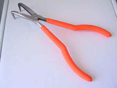
Location-wise, this ground location is very convenient because there is a pre-existing hole and at first glance it looks pretty easy to get to. In reality, it's a pain getting the ground lug installed due to one's inability to put a hand behind the metal plate where the ground lug mounts. First you have to have a pretty long arm to get it all the way behind that metal wall and thread the nut onto the master ground lug. Then I had to figure out a way to secure the nut on the back of that panel while I tightened the bolt on the front side of the panel. I ended up using a pair of bent needle-nose pliers....I got the bent part of the pliers through the long slotted cutout to the left of the ground lug and there was just enough room to grab onto the nut with the pliers and hold it tight.
These are like the pliers I used:
And here's a pic of the installed master ground lug:

Last edited by Ge|atinousFury; 12-18-2007 at 04:55 PM.


