DIY: Steering Wheel Control with PAC SWI-RC
 12-13-2012, 08:37 AM
#1

Since I had my Kenwood deck installed back in 2008, I’ve been semi-missing my steering wheel controls. So I decided to try the install myself. The following is my DIY for installing the PAC SWI-RC to enable the steering wheel controls in the Z. Sorry, but I didn’t take any pictures.
Removal of the center console
03 – 05 Z’s
http://liljerk.morpheus.net/350Z/dash_removal/
06+ Z’s
I used this guide posted by BTarb24.
https://my350z.com/forum/body-interi...by-guages.html
Supplies/Tools (My Method)
- PAC SWI-RC - $40.77 on Amazon
- Tap Splice Connectors (22-18 AWG)
- Crimp Cap Connectors (22-18 AWG)
- Pliers
- Wire Stripper
- Soldering Iron
- Heat Shrink
- Electrical Tape
- 18 gauge wires (Red, White, and Black)
These are the directions from PAC SWI’s site for my 2008 Z
http://pacaudio.com/SWI/SWIAppGuide....iOptions=Radio
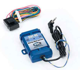
Here’s a picture of the PAC SWI-RC Unit
Here’s a picture of the factory Z connectors.
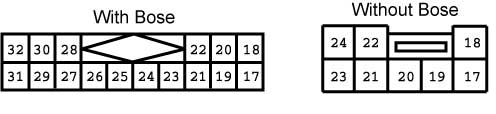
This is viewed from the pin side. Not the wire side.
I have the non-bose unit. For those that have bose units, the install should be very similar, although the Pin numbers will be different. For the non-bose plug, it was brown in color. Also note that we are only tapping into the wires going to this connector and not actually plugging this brown connector into something.
- For this install, you will only need the WHITE, RED, BLACK, and BLUE/YELLOW wire attached to the PAC SWI units. All other wires, bunch it up, tie it and forget about it.
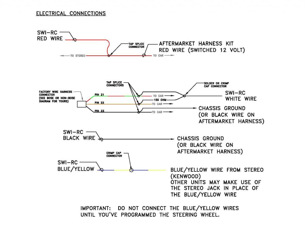
Refer to this diagram for the following
Prep Work (Before I touched the car)
- For the PAC SWI WHITE, RED, BLACK, and BLUE/YELLOW wires, I soldered on a 1 ft. extension for each wire. Reason being is that I placed the PAC SWI unit behind the A.C. controls (since there’s so much room behind there) and shoved the wires behind and up to where the stereo harness wires are. With all the soldered connections I covered it with heat shrink.
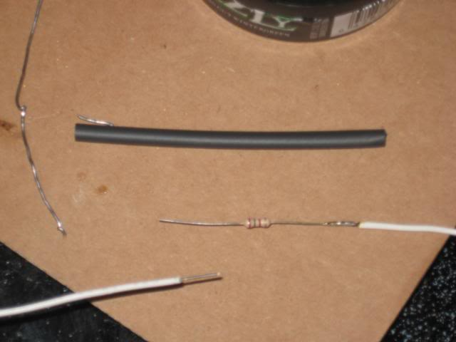
- For the PAC SWI WHITE wire, you’ll be attaching TWO (2) WHITE wires to it. I soldered the three wire connection together and covered it with shrink wrap and electrical tape. For one of the white wires you’re soldering on, you’ll need to solder a 150 ohm resister in (included in the PAC-SWI kit). You will not need to do anything to the other white wire. See diagram above. See Picture below:
Electrical Connections
Refer to my diagram above
Of course, I would recommend you disconnect your battery before removing the center console. I’ll assume you know how to remove the console from the tutorials above.
- Before I started connecting wires, set the rotary switch on the blue PAC SWI unit to #3. You can confirm this in the PAC SWI directions.
- Connect the two PAC SWI items together (the blue unit and the white plug with all the wires attached) and place/secure the PAC SWI unit into the space behind the A.C. controls. Run the PAC SWI WHITE, RED, BLACK, and BLUE/YELLOW wires behind and up to where the vehicle harness/stereo is located.
- Now for the connections, for the PAC SWI BLACK wire, you can either connect this to the black wire in the aftermarket wire harness OR connect it directly to the car. I would suggest your connect the wire to a chassis ground. Below is a picture of where you could connect it to.
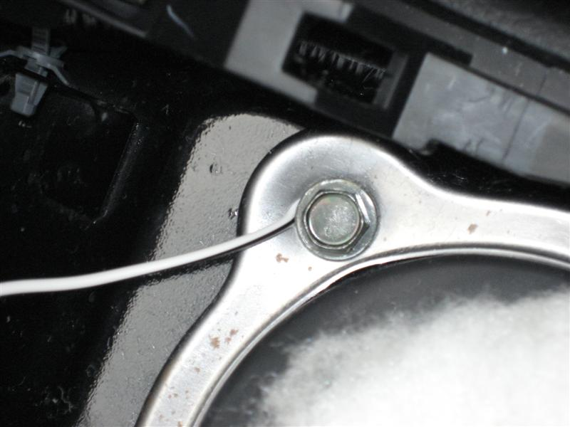
If in doubt, use a multimeter to test continuity with the existing black ground wire.
- From the factory Z connector picture above, I located the YELLOW/GREEN wire going to Pin 23, tapped into it using a tap splice connector, and secured it to the same ground connection as the PAC SWI BLACK wire.
- For the PAC SWI RED wire, connect to the RED wire in your aftermarket stereo harness. This red wire should be a switched 12v. I connected using the tap splice connector.
- For the PAC SWI WHITE wires, connect the wire with the 150 ohm resistor to the ORANGE wire going to Pin 22. Connect the other white wire (without the resistor) to the RED/GREEN wire going to Pin 21. I used tap splice connectors for these connections.
- LASTLY, you’ll have the PAC SWI BLUE/YELLOW wire to connect. DON’T CONNECT IT YET!! This connection to the stereo unit will take place AFTER you programmed your steering wheel controls. I tried to connect it before programming and it won’t let you. This should save you the hassle of being curious.
When you do make the connection, I used a crimp cap connector to connect the PAC SWI BLUE/YELLOW wire to the BLUE/YELLOW wire coming out from the back of the stereo head unit. Reason I did this was to be able to undo the connection if need be if I needed to remove the console from the car in the future. You’ll see what I mean.
- There are TWO (2) loop wires attached to the PAC SWI unit. DO NOT cut these. Leave these alone.
Below is how to program, best explained by PAC SWI:
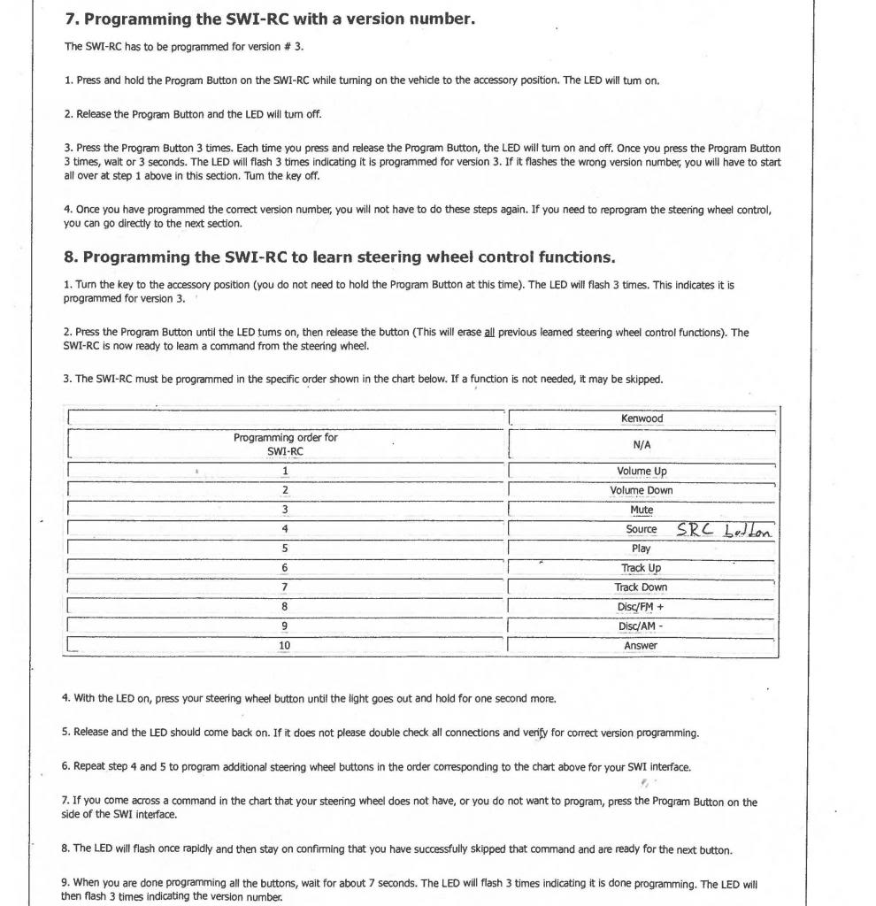
For my Z, I programmed everything back to stock except for my Power button. I made my Power button Mute.
Testing
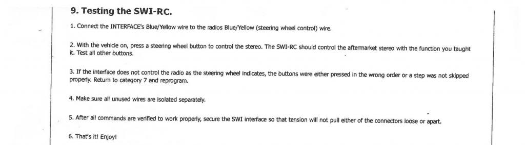
After you’ve made the connection with the blue/yellow wires, you’re DONE!
Removal of the center console
03 – 05 Z’s
http://liljerk.morpheus.net/350Z/dash_removal/
06+ Z’s
I used this guide posted by BTarb24.
https://my350z.com/forum/body-interi...by-guages.html
Supplies/Tools (My Method)
- PAC SWI-RC - $40.77 on Amazon
- Tap Splice Connectors (22-18 AWG)
- Crimp Cap Connectors (22-18 AWG)
- Pliers
- Wire Stripper
- Soldering Iron
- Heat Shrink
- Electrical Tape
- 18 gauge wires (Red, White, and Black)
These are the directions from PAC SWI’s site for my 2008 Z
http://pacaudio.com/SWI/SWIAppGuide....iOptions=Radio
Here’s a picture of the PAC SWI-RC Unit
Here’s a picture of the factory Z connectors.
This is viewed from the pin side. Not the wire side.
I have the non-bose unit. For those that have bose units, the install should be very similar, although the Pin numbers will be different. For the non-bose plug, it was brown in color. Also note that we are only tapping into the wires going to this connector and not actually plugging this brown connector into something.
- For this install, you will only need the WHITE, RED, BLACK, and BLUE/YELLOW wire attached to the PAC SWI units. All other wires, bunch it up, tie it and forget about it.
Refer to this diagram for the following
Prep Work (Before I touched the car)
- For the PAC SWI WHITE, RED, BLACK, and BLUE/YELLOW wires, I soldered on a 1 ft. extension for each wire. Reason being is that I placed the PAC SWI unit behind the A.C. controls (since there’s so much room behind there) and shoved the wires behind and up to where the stereo harness wires are. With all the soldered connections I covered it with heat shrink.
- For the PAC SWI WHITE wire, you’ll be attaching TWO (2) WHITE wires to it. I soldered the three wire connection together and covered it with shrink wrap and electrical tape. For one of the white wires you’re soldering on, you’ll need to solder a 150 ohm resister in (included in the PAC-SWI kit). You will not need to do anything to the other white wire. See diagram above. See Picture below:
Electrical Connections
Refer to my diagram above
Of course, I would recommend you disconnect your battery before removing the center console. I’ll assume you know how to remove the console from the tutorials above.
- Before I started connecting wires, set the rotary switch on the blue PAC SWI unit to #3. You can confirm this in the PAC SWI directions.
- Connect the two PAC SWI items together (the blue unit and the white plug with all the wires attached) and place/secure the PAC SWI unit into the space behind the A.C. controls. Run the PAC SWI WHITE, RED, BLACK, and BLUE/YELLOW wires behind and up to where the vehicle harness/stereo is located.
- Now for the connections, for the PAC SWI BLACK wire, you can either connect this to the black wire in the aftermarket wire harness OR connect it directly to the car. I would suggest your connect the wire to a chassis ground. Below is a picture of where you could connect it to.
If in doubt, use a multimeter to test continuity with the existing black ground wire.
- From the factory Z connector picture above, I located the YELLOW/GREEN wire going to Pin 23, tapped into it using a tap splice connector, and secured it to the same ground connection as the PAC SWI BLACK wire.
- For the PAC SWI RED wire, connect to the RED wire in your aftermarket stereo harness. This red wire should be a switched 12v. I connected using the tap splice connector.
- For the PAC SWI WHITE wires, connect the wire with the 150 ohm resistor to the ORANGE wire going to Pin 22. Connect the other white wire (without the resistor) to the RED/GREEN wire going to Pin 21. I used tap splice connectors for these connections.
- LASTLY, you’ll have the PAC SWI BLUE/YELLOW wire to connect. DON’T CONNECT IT YET!! This connection to the stereo unit will take place AFTER you programmed your steering wheel controls. I tried to connect it before programming and it won’t let you. This should save you the hassle of being curious.
When you do make the connection, I used a crimp cap connector to connect the PAC SWI BLUE/YELLOW wire to the BLUE/YELLOW wire coming out from the back of the stereo head unit. Reason I did this was to be able to undo the connection if need be if I needed to remove the console from the car in the future. You’ll see what I mean.
- There are TWO (2) loop wires attached to the PAC SWI unit. DO NOT cut these. Leave these alone.
Below is how to program, best explained by PAC SWI:
For my Z, I programmed everything back to stock except for my Power button. I made my Power button Mute.
Testing
After you’ve made the connection with the blue/yellow wires, you’re DONE!
Last edited by musubi; 12-13-2012 at 08:52 AM.
