DIY: Halo and Clear Lens mod on '06-'08 headlights
 04-17-2009, 10:21 PM
#1
New Member
Thread Starter
iTrader: (16)

Join Date: Apr 2007
Location: Denver
Posts: 399
Likes: 0
Received 0 Likes
on
0 Posts
There have been plenty of DIY’s on blacking out headlights, but when I tried to find info on adding halos and clear lenses to my lights, I came up a little short.
So, this guide will assume you have taken out your headlights, have already disassembled them, and have a plan for putting them back together.
Tools I used:
Phillips Screwdriver
Dremel
X-acto knife and/or Scissors
Lighter
Materials I used:
Thin Gasket Material (approx $4 at Pep-Boys or similar auto parts store)
Thick Gasket Material (approx $6 at Pep-Boys or similar auto parts store)
Zots – your mom or favorite aunt or maybe even your girl-friend/wife will know what these are… (approx $5 at Hobby Lobby or similar craft store) ( http://www.craftsetc.com/store/item.aspx?ItemId=84430&dep=51&cat=12&subcat=10&Search=Y )
Heat shrink tube (approx $2 at Microcenter or similar Radio-Shack type store)
Products I purchased:
Clear reproduction 3” STi lenses - $70 (http://store.theretrofitsource.com/product_info.php?cPath=29&products_id=85&osCsid=0399adf30bf9 84b34fbbb681a79dfc88 ) – Matt at The Retrofit Source is a good guy and will take care of you.
Halo – White – 95mm - $35 ( http://www.retrosolutionsllc.com/servlet/the-215/ANGELEYE-HALO-CCFL-WHITE/Detail )
Process:
Do the lens mod first.
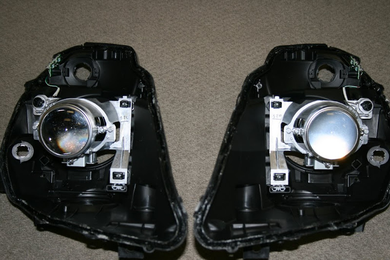
Fig 1: Clear Lens on left, factory Fresnel lens on right.
The STi clear lens is by far my favorite mod to the headlights. Aside from the color of the cut-off, the cut-off itself seems more distinct and dramatic.
The lenses come from The Retrofit Source with a spacer that is an aluminum wire bent into a ring shape. I had an issue with the ring chipping my first lens because of the sharp cut of the wire, so I made a spacer out of gasket material for my replacement lens.
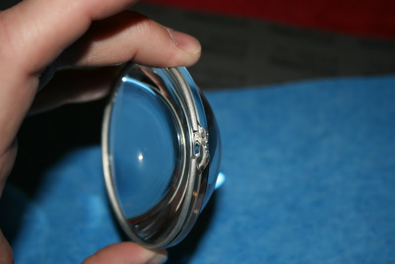
Fig 2: Chipped clear lens due to aluminum spacer ring
I found some thick gasket material and a thin gasket material at my local auto parts store, figuring that I could come up with some combination of the two that would match the spacer thickness. Turns out the two stacked together are darn near perfect!
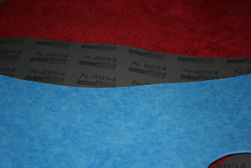
Fig 3: Gasket material found at Pep-boys. Blue is thick, gray is thin.

Fig 4: Spacer ring and factory gasket on left, thick and thin gasket material stacked on right. Darn near perfect!
Cut out two rings from each material using the original gasket out of the headlight as a guide. I recommend the X-acto knife for the inside of the ring instead of scissors.
Installation couldn’t be easier… remove the two screws on either side of the shroud, remove the old fresnel lens and gasket, insert your newly made gaskets (one thin, one thick, makes no difference in what order), place your new clear lens in the shroud and screw back in place.
If you wanted to do a demon-eye mod ( https://my350z.com/forum/body-interi...eadlights.html ) this would be the time.
It would not hurt to test out the cut-off by placing the housing back in the car and shining against a wall/garage door/whatever. In the pic below, you can see how the cut-off looks good on the LEFT, but incorrect on the RIGHT. I did not have my bulb correctly seated… because I didn’t test it first, I had to take my lights apart again to diagnose.
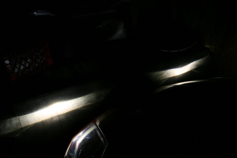
Fig 5: Cut offs done correctly (left side), and cut-off gone bad! (right side)

Fig 5a: Color with this lens
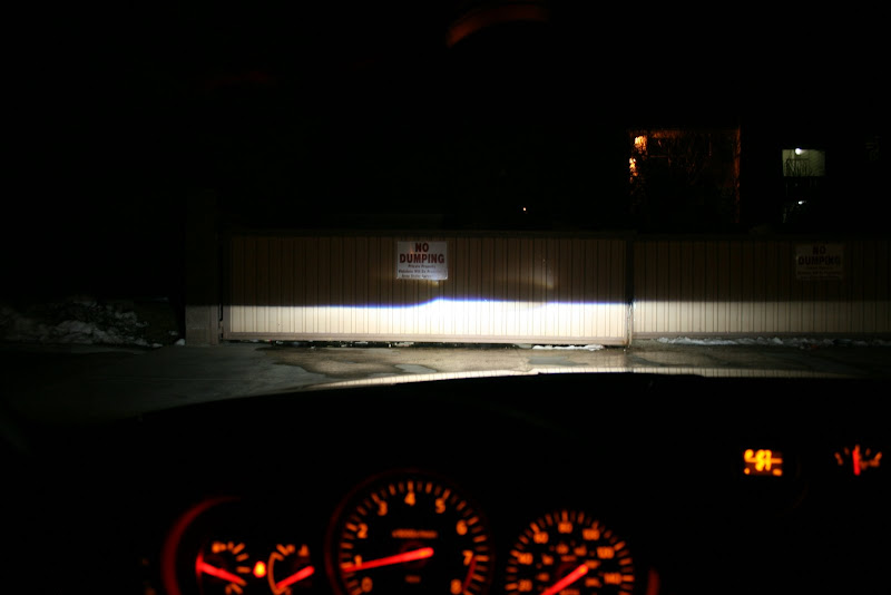
Fig 5b: Cut-offs as seen from driver's seat
So, this guide will assume you have taken out your headlights, have already disassembled them, and have a plan for putting them back together.
Tools I used:
Phillips Screwdriver
Dremel
X-acto knife and/or Scissors
Lighter
Materials I used:
Thin Gasket Material (approx $4 at Pep-Boys or similar auto parts store)
Thick Gasket Material (approx $6 at Pep-Boys or similar auto parts store)
Zots – your mom or favorite aunt or maybe even your girl-friend/wife will know what these are… (approx $5 at Hobby Lobby or similar craft store) ( http://www.craftsetc.com/store/item.aspx?ItemId=84430&dep=51&cat=12&subcat=10&Search=Y )
Heat shrink tube (approx $2 at Microcenter or similar Radio-Shack type store)
Products I purchased:
Clear reproduction 3” STi lenses - $70 (http://store.theretrofitsource.com/product_info.php?cPath=29&products_id=85&osCsid=0399adf30bf9 84b34fbbb681a79dfc88 ) – Matt at The Retrofit Source is a good guy and will take care of you.
Halo – White – 95mm - $35 ( http://www.retrosolutionsllc.com/servlet/the-215/ANGELEYE-HALO-CCFL-WHITE/Detail )
Process:
Do the lens mod first.
Fig 1: Clear Lens on left, factory Fresnel lens on right.
The STi clear lens is by far my favorite mod to the headlights. Aside from the color of the cut-off, the cut-off itself seems more distinct and dramatic.
The lenses come from The Retrofit Source with a spacer that is an aluminum wire bent into a ring shape. I had an issue with the ring chipping my first lens because of the sharp cut of the wire, so I made a spacer out of gasket material for my replacement lens.
Fig 2: Chipped clear lens due to aluminum spacer ring
I found some thick gasket material and a thin gasket material at my local auto parts store, figuring that I could come up with some combination of the two that would match the spacer thickness. Turns out the two stacked together are darn near perfect!
Fig 3: Gasket material found at Pep-boys. Blue is thick, gray is thin.
Fig 4: Spacer ring and factory gasket on left, thick and thin gasket material stacked on right. Darn near perfect!
Cut out two rings from each material using the original gasket out of the headlight as a guide. I recommend the X-acto knife for the inside of the ring instead of scissors.
Installation couldn’t be easier… remove the two screws on either side of the shroud, remove the old fresnel lens and gasket, insert your newly made gaskets (one thin, one thick, makes no difference in what order), place your new clear lens in the shroud and screw back in place.
If you wanted to do a demon-eye mod ( https://my350z.com/forum/body-interi...eadlights.html ) this would be the time.
It would not hurt to test out the cut-off by placing the housing back in the car and shining against a wall/garage door/whatever. In the pic below, you can see how the cut-off looks good on the LEFT, but incorrect on the RIGHT. I did not have my bulb correctly seated… because I didn’t test it first, I had to take my lights apart again to diagnose.
Fig 5: Cut offs done correctly (left side), and cut-off gone bad! (right side)
Fig 5a: Color with this lens
Fig 5b: Cut-offs as seen from driver's seat
Last edited by gr8scott_o; 04-26-2009 at 08:03 AM. Reason: added pics
 04-17-2009, 10:22 PM
#2
New Member
Thread Starter
iTrader: (16)
Join Date: Apr 2007
Location: Denver
Posts: 399
Likes: 0
Received 0 Likes
on
0 Posts
Now on to the halos…
There are two options for the halos… You can leave them in the plastic housings, or take them out.
If you leave them in the housings, they are easier to mount and are more durable. However, some say they are not as bright. As they mount a little further back, I can see how that might be true.
Taking them out of the housings will require fabrication of a mounting system, and they would be prone to breakage. Plan on purchasing extra rings if you go this route, just in case. But you may be rewarded by a brighter ring.
The housings ALMOST fit over the shroud with no modification, but were just a tad undersized. After weighing the brightness vs. durability issues, I decided to leave them in the housings, and fit the housings over the shrouds of the lenses.
I used a Dremel with the sanding barrel, and LIGHTLY went around the inside of the plastic housing. In my case, less than a millimeter needed to be removed, so like when voting, fit early and fit often.
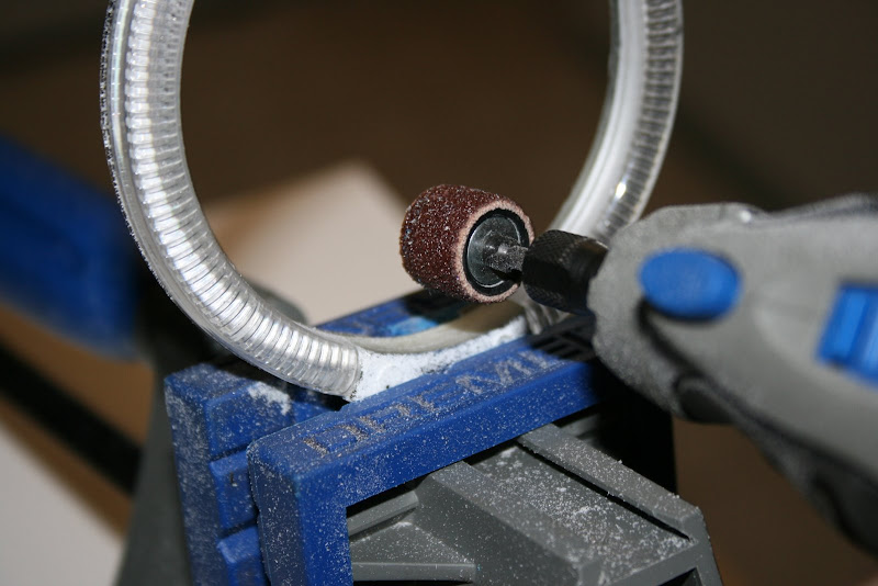
Fig 6: Dremel to fit. Go slow, and test-fit often! You want a tight fit over the shroud.
This produced a great deal of dust and debris. I recommend keeping your lights in a separate room while Dremeling.
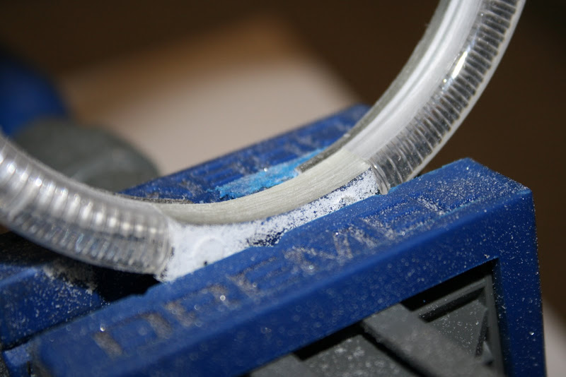
Fig 7: Lots of dust will result... dust is your enemy! Protect your lights from the dust!
I sanded until the housing just BARELY fit over the shroud, and would not go past the shroud housing seam. A tight fit here is preferred. Additionally, I did not want the housing of the halo to interfere with the high-beam rod on the underside of the light.
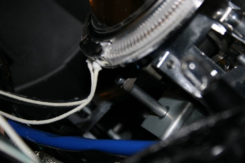
Fig 8: Make sure it fits tightly, but does not go back far enough to interfere with high-beam rod. NOTE: This is test fit, I ultimately mounted the rings with wires up.
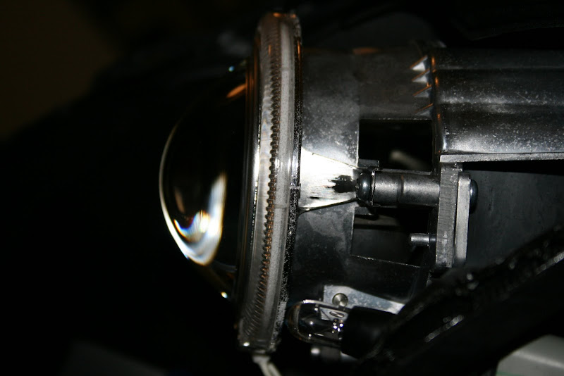
Fig 9: Housing fits tightly on shroud, and does not go past shroud seam.
Nothing but tension holds the halo in place. The cover will prevent the housing from moving forward, and if you fit it tightly, it should not move backwards at all.
I positioned the halo so the wires exited at the top of the housing, as the wires were quite long, and placing them at the top permitted a natural way to route the longer wire.
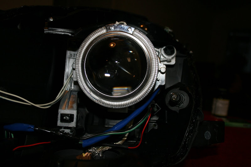
Fig 10: Laces out! Or, er, wires up.
My housings came with a silver cover over the wire area. Some pictures show the cover still on. I subsequently removed the cover, as it was tough to get the cover to fit so it was unseen with the cover on. If you find the cover tough to remove after sanding down the inside of the housing to fit over the housing, try baking the light for a few minutes at 250, as I noticed they almost fell off when I reopened my lights.
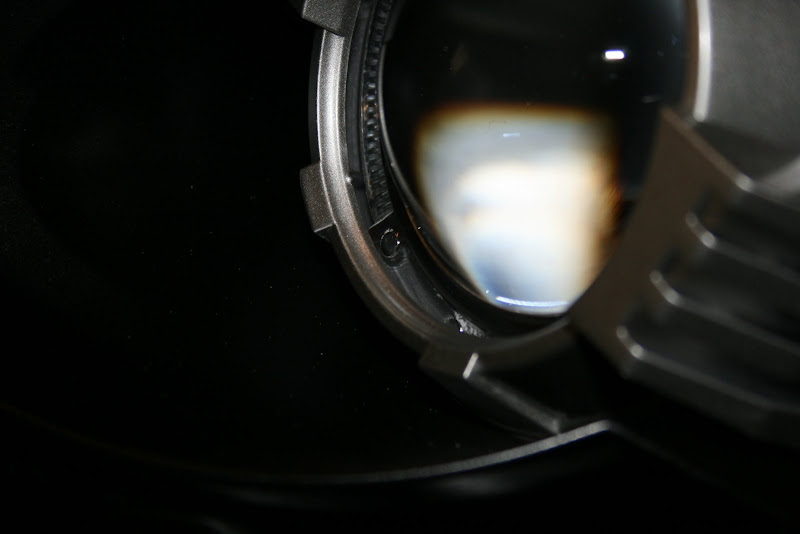
Fig 11: You can see the silver cover over the wire junction peaking through there... I subsequently removed it.
Now to prep the cover... I used blue painter’s masking tape all over the cover with the exception of the four high spots on the rim of the cover, and with 320 grit sandpaper removed the gray paint on those high areas. This will reveal the translucent quality of the plastic that makes up the cover, permitting your halos to shine through in those areas. I have seen some people sand the “front” of the high spots also, but I did not as I felt the extra effort would not pay off unless viewed from within a foot or so of the lights.
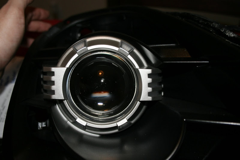
Fig 12: High spots on covers sanded clear. It's a little tough to tell here, but you can see the ridges of the halo housing through the four high spots.
There are two options for the halos… You can leave them in the plastic housings, or take them out.
If you leave them in the housings, they are easier to mount and are more durable. However, some say they are not as bright. As they mount a little further back, I can see how that might be true.
Taking them out of the housings will require fabrication of a mounting system, and they would be prone to breakage. Plan on purchasing extra rings if you go this route, just in case. But you may be rewarded by a brighter ring.
The housings ALMOST fit over the shroud with no modification, but were just a tad undersized. After weighing the brightness vs. durability issues, I decided to leave them in the housings, and fit the housings over the shrouds of the lenses.
I used a Dremel with the sanding barrel, and LIGHTLY went around the inside of the plastic housing. In my case, less than a millimeter needed to be removed, so like when voting, fit early and fit often.
Fig 6: Dremel to fit. Go slow, and test-fit often! You want a tight fit over the shroud.
This produced a great deal of dust and debris. I recommend keeping your lights in a separate room while Dremeling.
Fig 7: Lots of dust will result... dust is your enemy! Protect your lights from the dust!
I sanded until the housing just BARELY fit over the shroud, and would not go past the shroud housing seam. A tight fit here is preferred. Additionally, I did not want the housing of the halo to interfere with the high-beam rod on the underside of the light.
Fig 8: Make sure it fits tightly, but does not go back far enough to interfere with high-beam rod. NOTE: This is test fit, I ultimately mounted the rings with wires up.
Fig 9: Housing fits tightly on shroud, and does not go past shroud seam.
Nothing but tension holds the halo in place. The cover will prevent the housing from moving forward, and if you fit it tightly, it should not move backwards at all.
I positioned the halo so the wires exited at the top of the housing, as the wires were quite long, and placing them at the top permitted a natural way to route the longer wire.
Fig 10: Laces out! Or, er, wires up.
My housings came with a silver cover over the wire area. Some pictures show the cover still on. I subsequently removed the cover, as it was tough to get the cover to fit so it was unseen with the cover on. If you find the cover tough to remove after sanding down the inside of the housing to fit over the housing, try baking the light for a few minutes at 250, as I noticed they almost fell off when I reopened my lights.
Fig 11: You can see the silver cover over the wire junction peaking through there... I subsequently removed it.
Now to prep the cover... I used blue painter’s masking tape all over the cover with the exception of the four high spots on the rim of the cover, and with 320 grit sandpaper removed the gray paint on those high areas. This will reveal the translucent quality of the plastic that makes up the cover, permitting your halos to shine through in those areas. I have seen some people sand the “front” of the high spots also, but I did not as I felt the extra effort would not pay off unless viewed from within a foot or so of the lights.
Fig 12: High spots on covers sanded clear. It's a little tough to tell here, but you can see the ridges of the halo housing through the four high spots.
Last edited by gr8scott_o; 04-17-2009 at 11:19 PM. Reason: added pics
04-17-2009, 10:23 PM
#3
New Member
Thread Starter
iTrader: (16)
Join Date: Apr 2007
Location: Denver
Posts: 399
Likes: 0
Received 0 Likes
on
0 Posts
Almost done… all that is left is to mount the converter for the halos and wire them up!
The CCFL rings are actually run off of AC, and require a DC to AC converter to be placed within the housing somewhere. The spot I found worked best for me was near the wire plug in the lower front corner of the light housing. As you can see, there is plenty of clearance for the converter in that area.
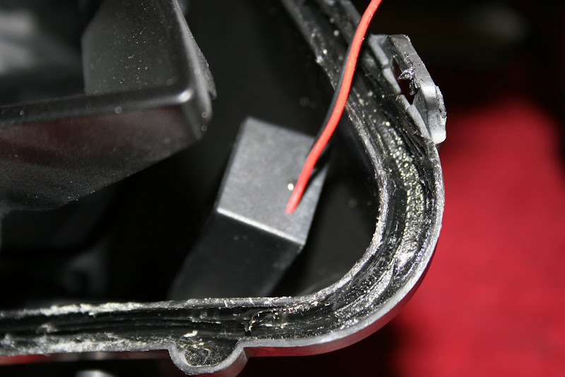
Fig 13: Plenty of clearance for converter in this corner.
Now how to mount the converter? I wanted a solution that would be easy to remove if I needed to make a change later, but was solid enough to survive the daily rigors of driving. Epoxy or silicone RTV seemed too permanent.
I can actually thank my mom for the idea here… she happened to be in town visiting as I was putting these back together. As I was explaining the dilemma, she suggested stuff that is used in the craft of scrap-booking, called “Zots 3D”. It appears to be a big lump of the glue used to make Post-its.
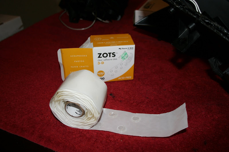
Fig 14: Yes, seriously, scrap-booking supplies... they work great!
I figured for the roughly $5 it cost to buy the smallest box I could find, it was worth the gamble. Turns out, it was the PERFECT solution! The Zots held tight, and when I reopened my lights I found that they got somewhat stickier during the heating cycle, yet were still removable.
I never in a million years would have imagined that I would utilize something from the scrap-booking world on my Z, but nevertheless I put three of those suckers on the bottom of my halo converters and stuck it as close to the wire plug as I could. Additionally, I used one more Zot to secure the wires to the side of the light housing to keep them tidy and out of the way.
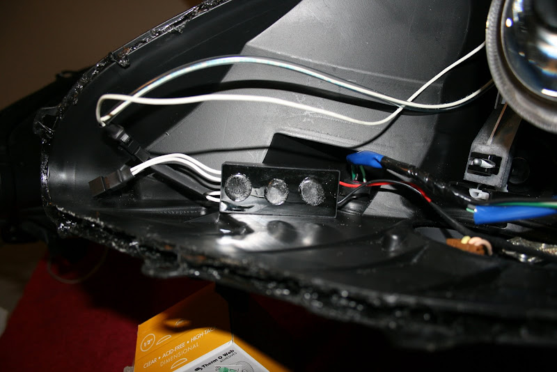
Fig 15: Three Zots to the bottom of the converter.
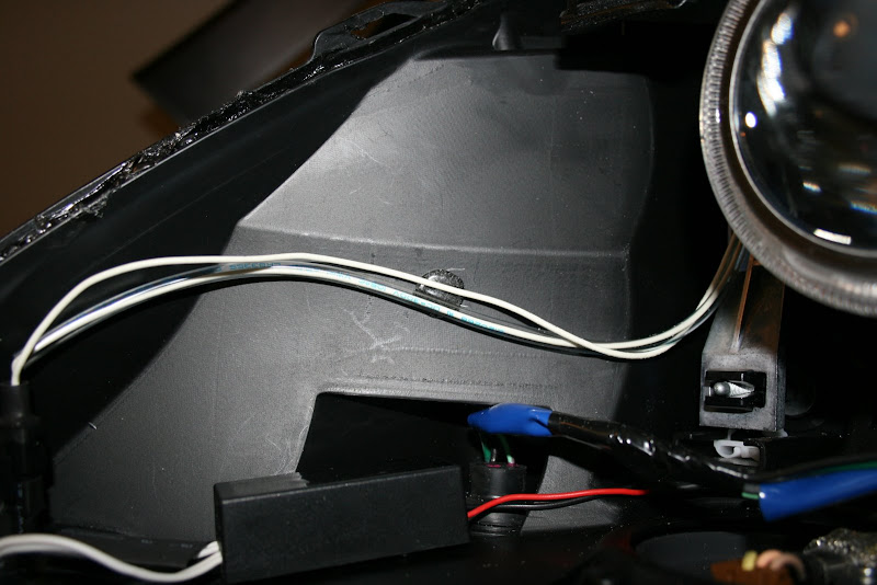
Fig 16: And one Zot to keep wires tucked up out of the way and tidy.
For the wiring, I slipped a piece of shrink tube over my wire from the converter. Then, I found the wires that went up to the LED sidemarkers, and traced them back to the plug that is near the lens shroud. In my case, the wires were black and green.
I referenced the side marker circuit board to determine which wires were positive and negative, and wired up my halos appropriately. The instructions that came with my halos indicated that the pos and neg was really important to get right, so double check that you wire yours up correctly.
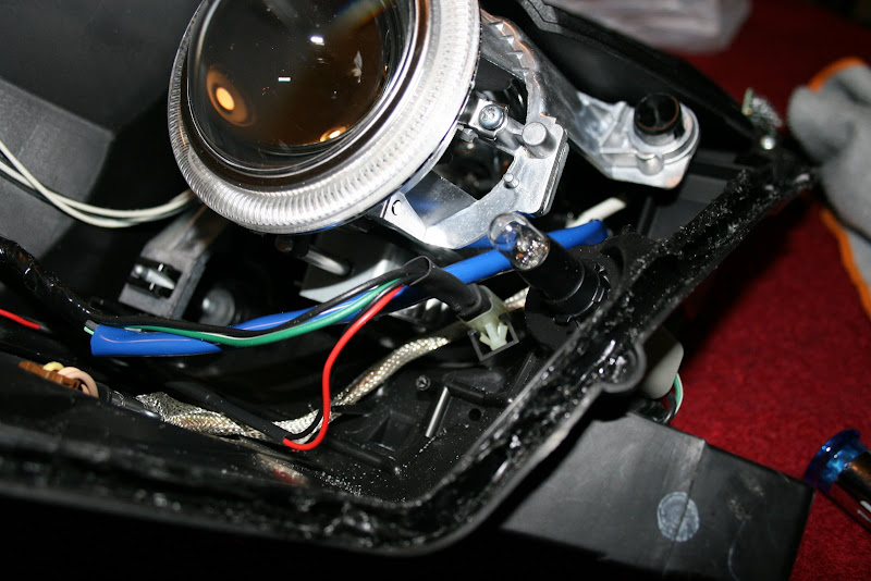
Fig 17: Plug I used to wire up converter... a little heat-shrink, a little heat applied, violia!
Reassemble your lights, and enjoy!
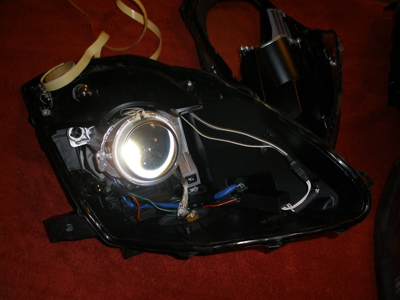
Fig 18: Overview shot showing wire routing, silver cover removed, and converter in lower right corner near plug.
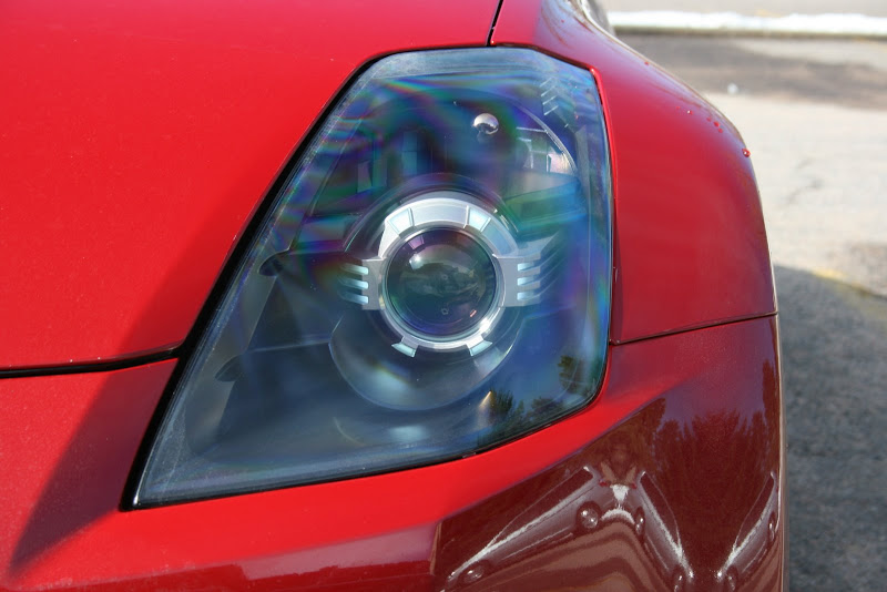
Fig 19: Assembled and installed, daylight, halos on.
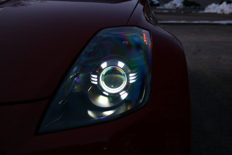
Fig 20: Dusk
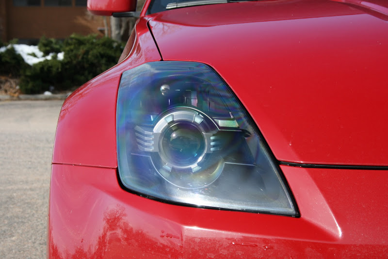
Fig 21: Pass side, halos on.
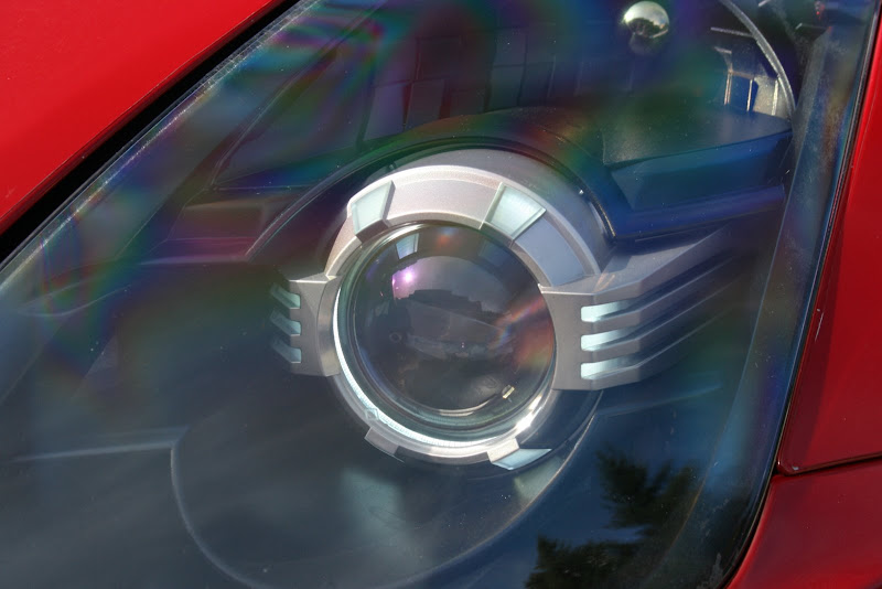
Fig 22: Close-up.
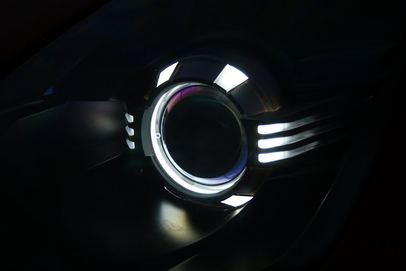
Fig 23: Dusk Closeup
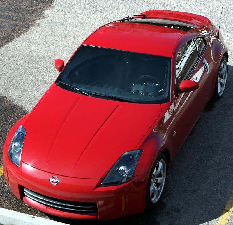
Fig 24: Shameless Vanity Shot
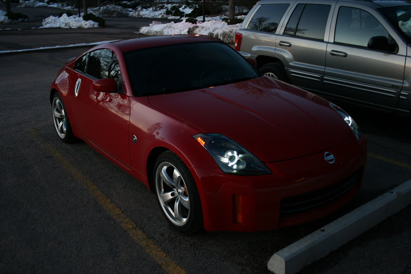
Fig 25: Dusk Shameless Vanity Shot
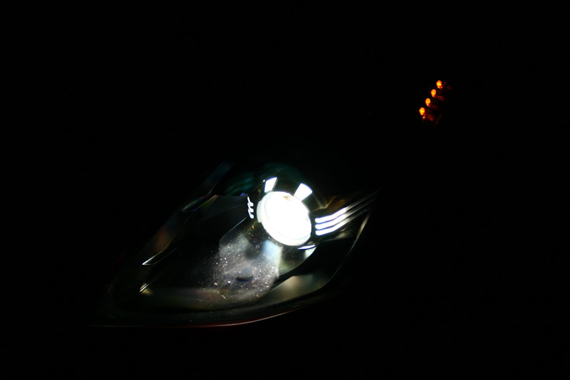
Fig 26: Night, Lights on. Since halos come on with parking lights, they are on also.
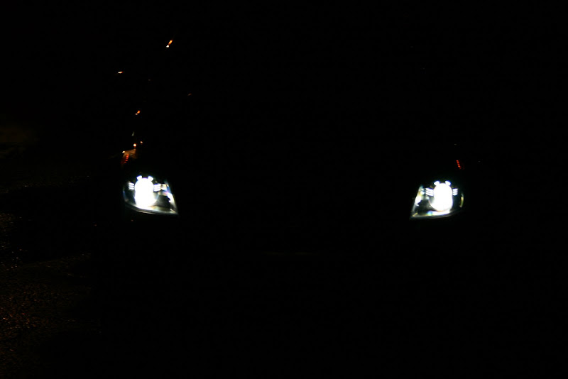
Fig 27: Night, all on.
The CCFL rings are actually run off of AC, and require a DC to AC converter to be placed within the housing somewhere. The spot I found worked best for me was near the wire plug in the lower front corner of the light housing. As you can see, there is plenty of clearance for the converter in that area.
Fig 13: Plenty of clearance for converter in this corner.
Now how to mount the converter? I wanted a solution that would be easy to remove if I needed to make a change later, but was solid enough to survive the daily rigors of driving. Epoxy or silicone RTV seemed too permanent.
I can actually thank my mom for the idea here… she happened to be in town visiting as I was putting these back together. As I was explaining the dilemma, she suggested stuff that is used in the craft of scrap-booking, called “Zots 3D”. It appears to be a big lump of the glue used to make Post-its.
Fig 14: Yes, seriously, scrap-booking supplies... they work great!
I figured for the roughly $5 it cost to buy the smallest box I could find, it was worth the gamble. Turns out, it was the PERFECT solution! The Zots held tight, and when I reopened my lights I found that they got somewhat stickier during the heating cycle, yet were still removable.
I never in a million years would have imagined that I would utilize something from the scrap-booking world on my Z, but nevertheless I put three of those suckers on the bottom of my halo converters and stuck it as close to the wire plug as I could. Additionally, I used one more Zot to secure the wires to the side of the light housing to keep them tidy and out of the way.
Fig 15: Three Zots to the bottom of the converter.
Fig 16: And one Zot to keep wires tucked up out of the way and tidy.
For the wiring, I slipped a piece of shrink tube over my wire from the converter. Then, I found the wires that went up to the LED sidemarkers, and traced them back to the plug that is near the lens shroud. In my case, the wires were black and green.
I referenced the side marker circuit board to determine which wires were positive and negative, and wired up my halos appropriately. The instructions that came with my halos indicated that the pos and neg was really important to get right, so double check that you wire yours up correctly.
Fig 17: Plug I used to wire up converter... a little heat-shrink, a little heat applied, violia!
Reassemble your lights, and enjoy!
Fig 18: Overview shot showing wire routing, silver cover removed, and converter in lower right corner near plug.
Fig 19: Assembled and installed, daylight, halos on.
Fig 20: Dusk
Fig 21: Pass side, halos on.
Fig 22: Close-up.
Fig 23: Dusk Closeup
Fig 24: Shameless Vanity Shot
Fig 25: Dusk Shameless Vanity Shot
Fig 26: Night, Lights on. Since halos come on with parking lights, they are on also.
Fig 27: Night, all on.
Last edited by gr8scott_o; 04-19-2009 at 07:17 PM. Reason: added pics


Trending Topics


 04-26-2009, 07:49 AM
#16

Excellent write-up Scott! This site definitely needed it.
All, although the project may appear daunting on the surface, it really is quite simple. Anyone with very basic DIY skills can complete it, especially with directions that are this detailed. Plus once you have the lights open, you will note that there are MANY creative ways of doing every step of these mods. My only advice is to take your time and evaluate all your options. Good luck!
P.S: Halos are true workhorses; mine have been in for over a year and work perfectly. I recently re-did them but that was more of a "want" than a need. These things are amazingly reliable.
04-27-2009, 10:57 PM
#17
Registered User

Join Date: Mar 2007
Location: San Jose, CA
Posts: 13
Likes: 0
Received 0 Likes
on
0 Posts
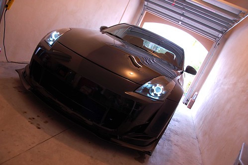
these are my halos. i removed them from the clear plastic casing. i broke one of them the first time around so i had to order another one. this set me back one week. wish this DIY was up a couple weeks ago. i'm really happy with the results. if anyone is not confident in doing this mod, i say just bite the bullet and do it. it's not that bad. can't really tell from these pics but the color of my car is Pikes Peak White.
04-28-2009, 07:49 AM
#18
New Member
iTrader: (4)

Join Date: Jul 2008
Location: Houston (Sugar Land)
Posts: 348
Likes: 0
Received 0 Likes
on
0 Posts
no way ur car looks straight orange. wierd
wierd
anyways great job op on figuring out you can grind down the halo. ur going to save everyone alot of money! wish i would have know this before i broke mine.
btw my haols pictured below are fited with the "open" halo not the sanded down one so use it to compare with the light output of the ops. look to be the same so i would go with the safe route. no need to risk it
wierdanyways great job op on figuring out you can grind down the halo. ur going to save everyone alot of money! wish i would have know this before i broke mine.
btw my haols pictured below are fited with the "open" halo not the sanded down one so use it to compare with the light output of the ops. look to be the same so i would go with the safe route. no need to risk it
04-28-2009, 04:38 PM
#19
New Member
Thread Starter
iTrader: (16)
Join Date: Apr 2007
Location: Denver
Posts: 399
Likes: 0
Received 0 Likes
on
0 Posts
Usmanasif and I were at a meet this weekend... IIRC, he has the silver backing but no clear cover. Output was slightly brighter on his, if I were to put a figure to it I would say less than 10%.
He has done a couple of other really unique things while he had his apart, I will let him comment on his mods
He has done a couple of other really unique things while he had his apart, I will let him comment on his mods
