Another LS Build
 05-16-2014, 12:52 PM
#1

Hey everyone,
I figured this would catch a bit of interest here. I recently had a failure of my clutch slave cylinder on my 350z and decided rather than replace the slave cylinder to kick it up a notch. Instead I'm swapping the VQ35HR out for a LS3, because it obviously makes sense.
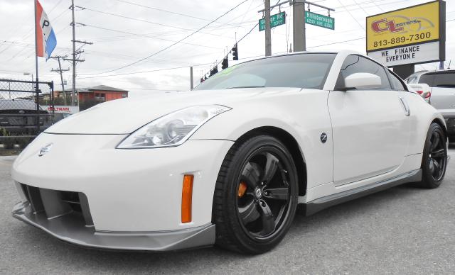
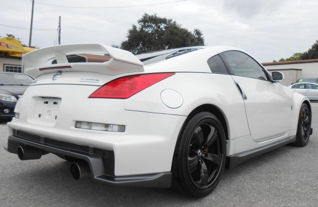
Here is the car I bought it a about 5 months ago with the swap in mind, the car decided it was ready.
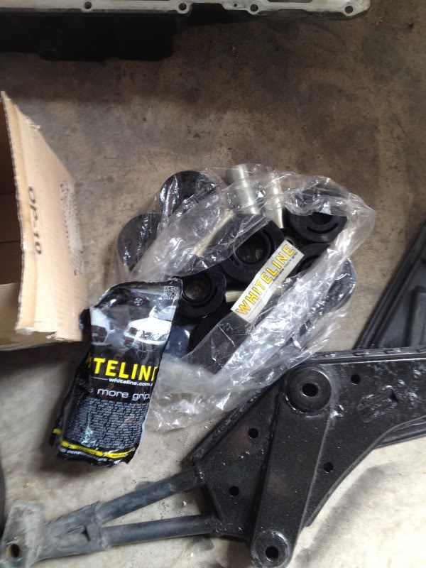
As of right now the build is focused around a 6.2L LS3 Motor out of a 2012 Camaro SS. I've put in a GMPP street cam in it for now but that may change later if I go forced induction or need more power. The intake is an off the shelf K&N unit. the exhaust will be a 2.5inch dual exhaust. I'll put the power down through a Tremec t-56(TR6060) Magnum Transmission with a Mcleod clutch and hydraulic throw out bearing. In the pumpkin, I'll put a Cusco 2 way locking diff. Whiteline bushings will be installed throughout the car.
For the interior i'm looking at Corbeau seats with a 6 point harness on planted seat mounts.
I figured this would catch a bit of interest here. I recently had a failure of my clutch slave cylinder on my 350z and decided rather than replace the slave cylinder to kick it up a notch. Instead I'm swapping the VQ35HR out for a LS3, because it obviously makes sense.
Here is the car I bought it a about 5 months ago with the swap in mind, the car decided it was ready.


As of right now the build is focused around a 6.2L LS3 Motor out of a 2012 Camaro SS. I've put in a GMPP street cam in it for now but that may change later if I go forced induction or need more power. The intake is an off the shelf K&N unit. the exhaust will be a 2.5inch dual exhaust. I'll put the power down through a Tremec t-56(TR6060) Magnum Transmission with a Mcleod clutch and hydraulic throw out bearing. In the pumpkin, I'll put a Cusco 2 way locking diff. Whiteline bushings will be installed throughout the car.
For the interior i'm looking at Corbeau seats with a 6 point harness on planted seat mounts.

The following users liked this post:
Franchyze (10-09-2015)
05-16-2014, 01:31 PM
#2
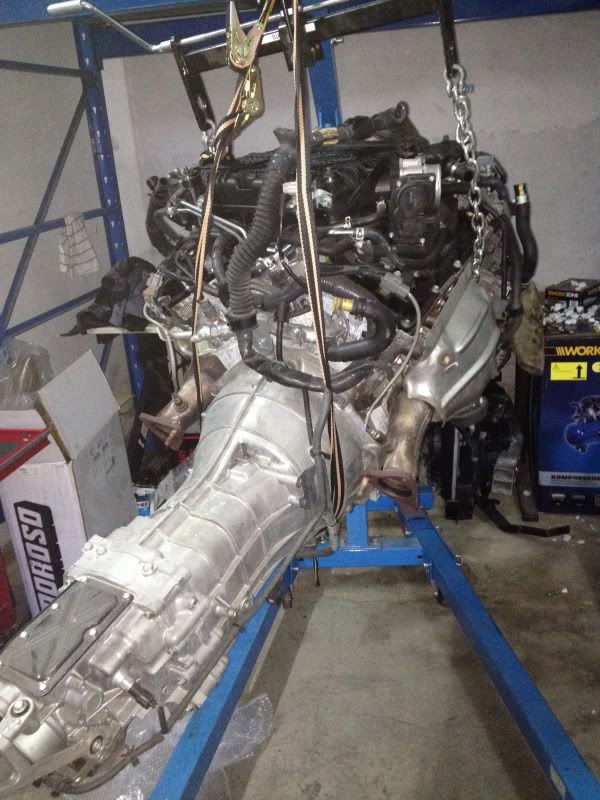
Here is the mandatory build up shot.
The engine and trans are already together, I had been running this setup previously in my FD3S which is now in the josh's hands.
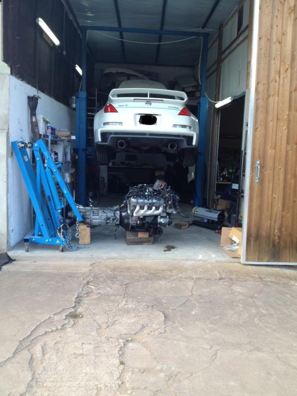
To start with, ripping the motor out... there are 3 ways to do it.
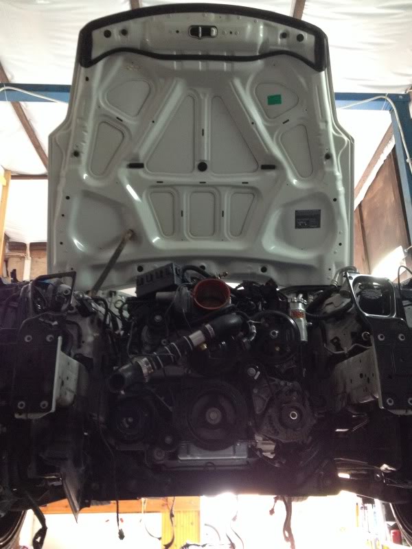
1. You can drop the engine/subframe/trans out the bottom if you have access to a lift.
2. Remove the front end and bring it out the front.
3. use a engine hoist and bring it out the top.
I chose method 2, although in retrospect I should have done 1, more on this later.
So here is with the front clip removed.
And the engine comes out.
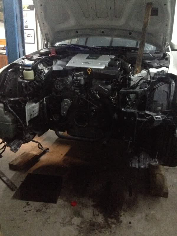
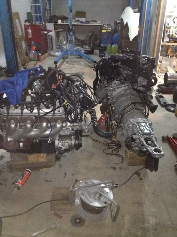
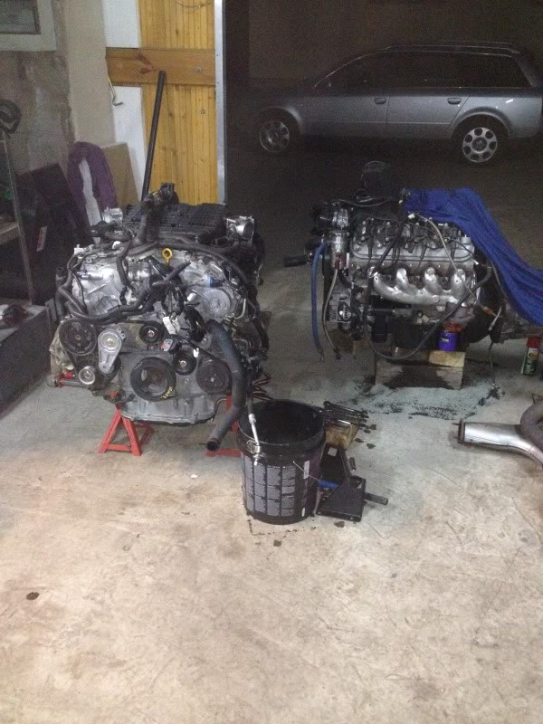
Here are some size references from the VQ vs. the LS

The engine and trans are already together, I had been running this setup previously in my FD3S which is now in the josh's hands.
To start with, ripping the motor out... there are 3 ways to do it.
1. You can drop the engine/subframe/trans out the bottom if you have access to a lift.
2. Remove the front end and bring it out the front.
3. use a engine hoist and bring it out the top.
I chose method 2, although in retrospect I should have done 1, more on this later.
So here is with the front clip removed.

And the engine comes out.

Here are some size references from the VQ vs. the LS

 05-16-2014, 01:56 PM
#3
So most of the day was spent doing some mild changes to the LS motor to prep it. The mounts Being used do not allow for the stock oil pan to be used, luckily the kit provides an oil pan that will. The downside is I no longer have a spot to mount my oil pressure sensor.
Here is the mounts and new oil pan on the subframe.
This is also the reason why if I were to do this again I would drop the motor out the bottom. There simply is no way I found to get the engine and transmission into the car with the subframe and power steering pump installed on the car. I spent more time trying other ways to get it in around the subframe that I could have just turned the wrenches and dropped the subframe and bolted it all back up. What can I say I'm very stubborn.
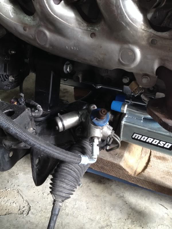
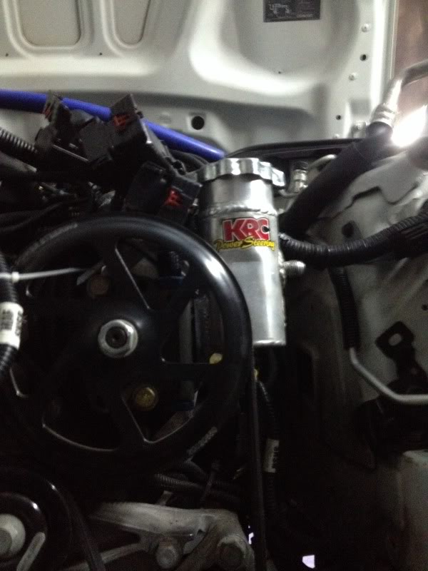
Since the steering will no longer be adapted by how fast the car is going I didnt want to over or underdrive the power steering rack. to get by this I bought a slick little KRC power steering pump that has different diameter flow restrictors that allow you to pump as much or as little as you want dialing in exactly how much assistance you want.
Here is the mounts and new oil pan on the subframe.

This is also the reason why if I were to do this again I would drop the motor out the bottom. There simply is no way I found to get the engine and transmission into the car with the subframe and power steering pump installed on the car. I spent more time trying other ways to get it in around the subframe that I could have just turned the wrenches and dropped the subframe and bolted it all back up. What can I say I'm very stubborn.
Since the steering will no longer be adapted by how fast the car is going I didnt want to over or underdrive the power steering rack. to get by this I bought a slick little KRC power steering pump that has different diameter flow restrictors that allow you to pump as much or as little as you want dialing in exactly how much assistance you want.
 05-17-2014, 01:18 PM
#4
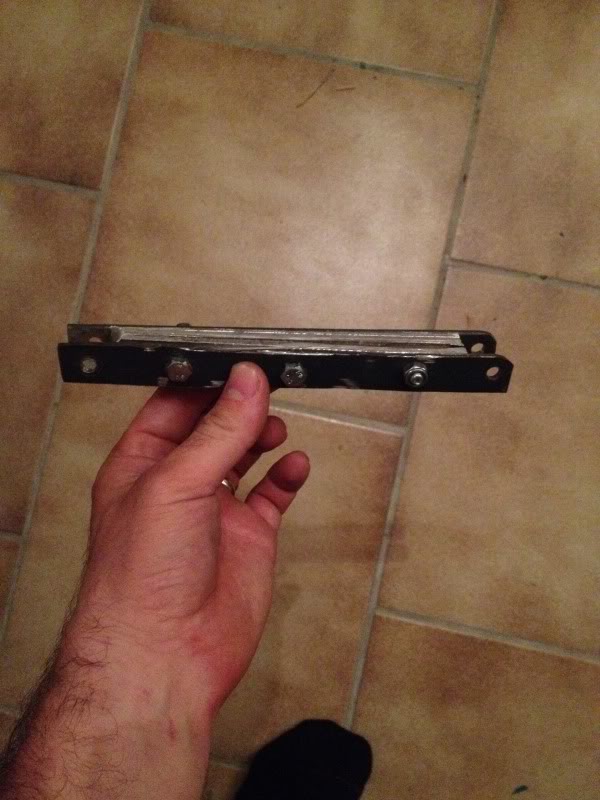
One of the downsides to using the Magnum transmission is its length. For this porject and most other LS swaps, it is simply too short. The shifter position is a little over 6 inches forward from the location of a a GTO/monaro. So, I had to make a shifter location adapter.
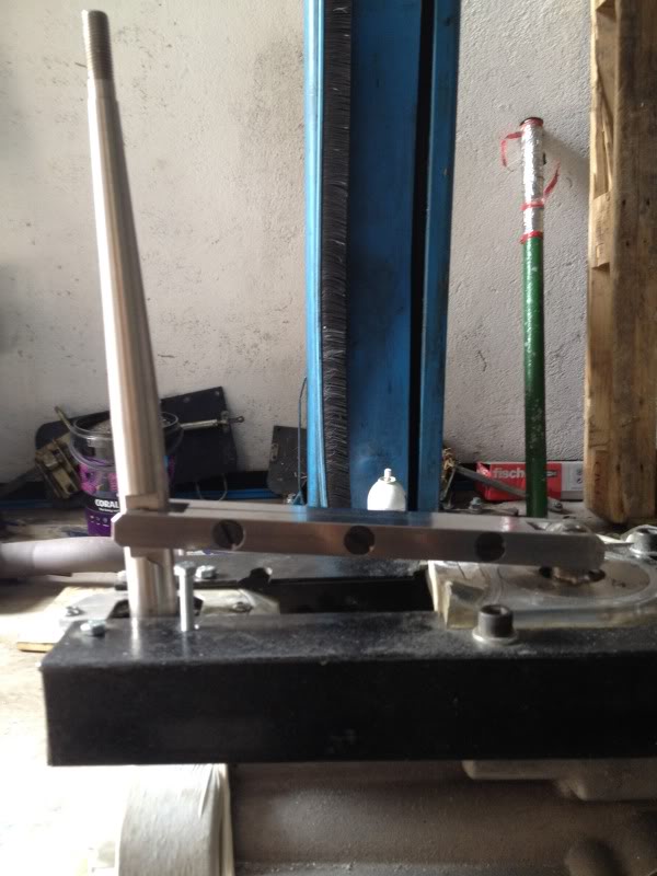
First I tried to use a offset shifter adapter but the arm on it was so long it would hit the transmission tunnel top on 1,3,and 5th gear shifts. Decided to hack apart 2 shifters I had laying around and connected an arm between the 2. So here is the first mock up of the arm to prove my concept.
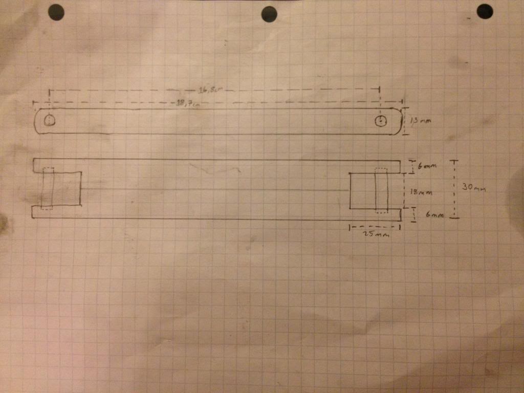
After that I made up some schematics to give to a machine shop, which is below for anyone who may do the same thing.
Here was the finished arm between the 2 shifters.
The shifters function flawlessly, I made a more permanant mount for the rear shifter but forgot to snap a picture of it. I'm about 97% happy with the location as its centered in the shifter hole of the chassis, it just appears to be slightly canted towards the driver.
First I tried to use a offset shifter adapter but the arm on it was so long it would hit the transmission tunnel top on 1,3,and 5th gear shifts. Decided to hack apart 2 shifters I had laying around and connected an arm between the 2. So here is the first mock up of the arm to prove my concept.

After that I made up some schematics to give to a machine shop, which is below for anyone who may do the same thing.

Here was the finished arm between the 2 shifters.

The shifters function flawlessly, I made a more permanant mount for the rear shifter but forgot to snap a picture of it. I'm about 97% happy with the location as its centered in the shifter hole of the chassis, it just appears to be slightly canted towards the driver.
05-17-2014, 01:41 PM
#5
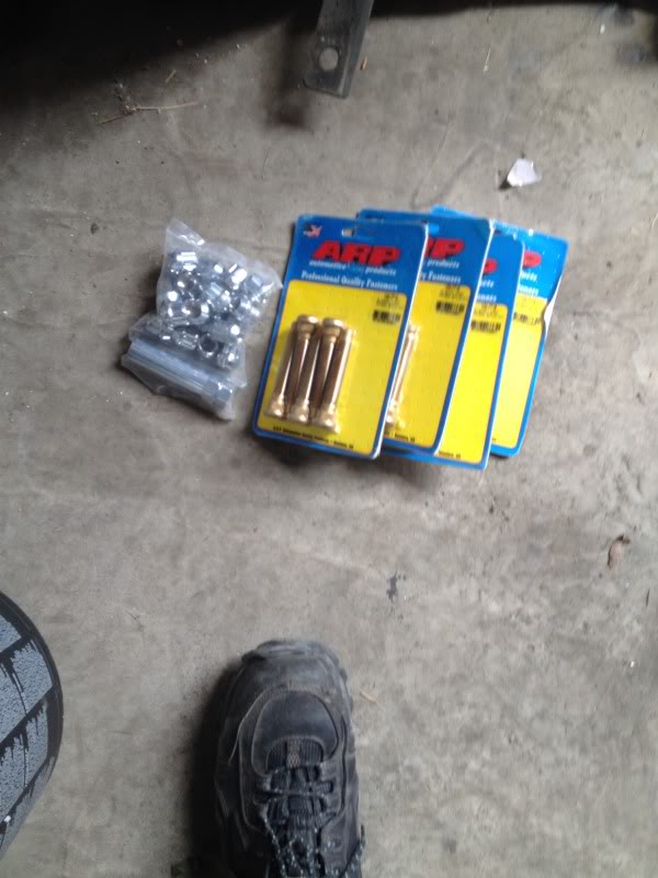
The post man was good to me today, the whiteline bushings and longer studs finally came in.
But onto the work...
I started to get onto the electronics today. The 350z uses a canbus system for all data throughout the car. Once analog data for the sensors reaches the factory Z ECU it gets translated into canbus. This presents an issue for the average person and leaves a couple choices. first off you can use the stock oil and water sensors to feed into a hacked up loom into the Z ecu and have the motor run off the GM ECU. The speedo runs off the ABS sensors and doesn't go through the ECU. The tacho will also not function, it uses a combined signal of the crank and cam position sensors which when fed together form an uneven 5 pulse per rev signal. Without a digital converter the tacho gauge is not compatible and even with the converter, duplicating the 5 abnormal width pulses may not be possible.
OR
Buy yourself some speedhut or other aftermarket gauges and call it a day.I happened to have some gauges from a previous swap laying around so guess which I did.
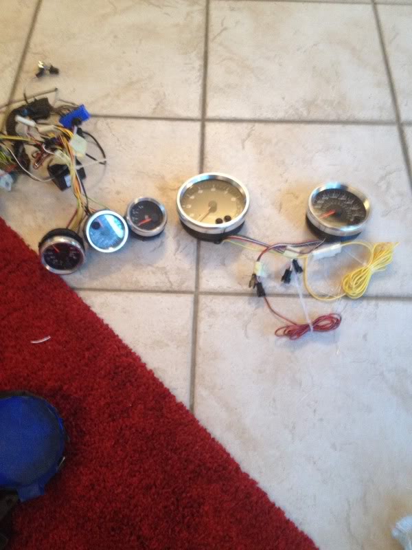
To get them to fit I started making some fiberglass plugs to mount the gauges to, later the plugs will sit in the factory gauge cluster.
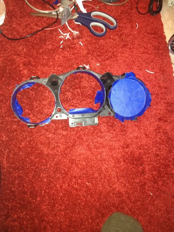
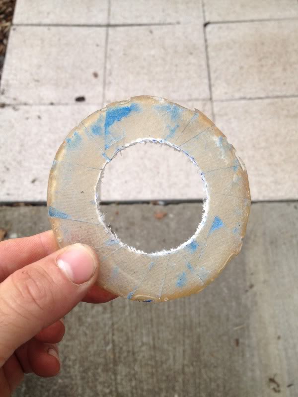
Unfortunately I had to use a crappy polyester resin from a local hardware store instead of the normal stuff I use so my release agent didn't work so great and it also left a decent amount of voids. I'll fill those and paint it later.
 05-17-2014, 02:39 PM
#7
I had a Vortech S/C'ed VQ in my 05, I just got frustrated with the 400whp wall I hit with it. plus the costs really were starting to mount after that and fuel consumption went up. With the LS3 I'm hoping for an easy 450whp and decent numbers on the gas mileage.
Trending Topics
 05-18-2014, 12:39 PM
#12
So it probably should be mentioned that this is going to be a 50 state CARB approved swap. You may have noticed in some of the photos of the engine it uses factory manifolds. also its using a reworked set of OEM cats for the inspection.
A lot of the work today was busy work, nothing terribly interesting unfortunately.
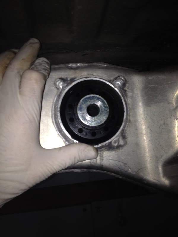
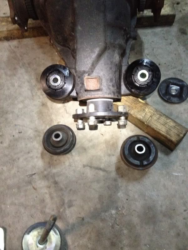
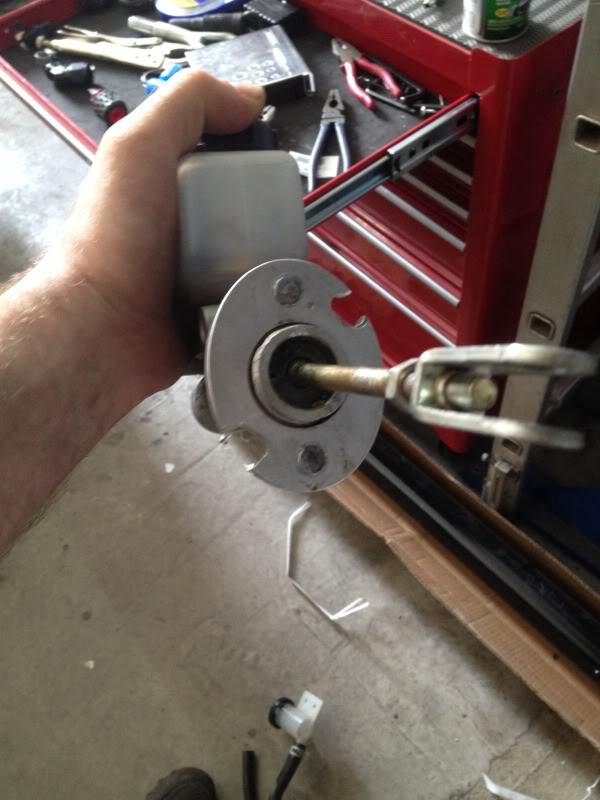
To start with, I found the rear differential bushing torn which is common so for a good part of the day I spent getting the bushings on the diff and rear subframe replaced.
Now the new one.
Also I started working out the clutch hydraulics, a willwood 7/8ths unit. The only problem being that I need to put in a 90 degree elbow right off the end of the MC due to the wheel well. Its a AN-3 fitting size so I'll have to wait a few days for that part to arrive since nobody seems to carry an AN-3...
Also the motor is in the car, woohoo!
A lot of the work today was busy work, nothing terribly interesting unfortunately.
To start with, I found the rear differential bushing torn which is common so for a good part of the day I spent getting the bushings on the diff and rear subframe replaced.

Now the new one.


Also I started working out the clutch hydraulics, a willwood 7/8ths unit. The only problem being that I need to put in a 90 degree elbow right off the end of the MC due to the wheel well. Its a AN-3 fitting size so I'll have to wait a few days for that part to arrive since nobody seems to carry an AN-3...

Also the motor is in the car, woohoo!
 05-22-2014, 06:41 AM
#13
Registered User

I've been really interested swaps for about a year now and have studied a few others before you. I'm wondering what the size difference is between some of the different blocks and how they fit. Did a 6.2L fit without hacking out the second firewall?? (couldn't tell from pics you have so far). It SEEMED to me like some were limiting themselves to a 5.3L for fitment reasons but I may be all wet. I'm trying to pay attention to how each motor is fitting in the different builds I'm following.
Thanks for the details on the ECU problems too. That explains the technical challenges a little better than other builds I have seen. Can't wait to see the pods when you are done. I've done some fiberglass work for speaker enclosures and if I ever do a swap, wouldn't mind doing some more custom work if it turns the nearly impossible task of factory gauges to something very simple.
Also love how easily you made your shifter linkage. Can't wait to hear it run!
05-22-2014, 08:39 AM
#14
hatersgonnahate

iTrader: (162)
so if you got a flat tire would you do an all out suspension build with ohlins and the works? lol.
Gl on the build. Interested in the final numbers and how well it runs like a stock car (no safety bypass, working gauges, working accessories)
Gl on the build. Interested in the final numbers and how well it runs like a stock car (no safety bypass, working gauges, working accessories)
05-25-2014, 12:28 PM
#16
Today was spent finishing the clutch hydraulics and the cooling system.
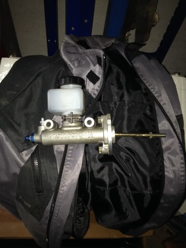
A couple details about using an aftermarket master cylinder. The mounting holes for the MC on the Z are offset by about 20 degrees from vertical. Most master cylinders have mounting holes that are vertical. To resolve this I made an adapter plate out of 1/4 inch aluminum. Fairly simple to do, just cut out the desired piece drill hold to put press in studs into for the MC to mount to and drill the holes for the bolts to go through the firewall.
Another note on the MC, you must have a 90 degree AN-3 fitting to come out of the MC, there is no room to have a an-3 to an-4 adapter and then a 90 degree fitting. after that I simply plumber it to the braided line on my hydraulic throw out bearing.
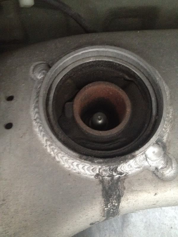
Up next was the cooling system. The LS motor has its coolant lines opposite to the Z. For the top radiator pipe it was simple, 2x 90 degree hoses and a 35mm pipe to connect them. The bottom however was a little more difficult. The engine side does not come out straight from the engine, its at a 45 degree angle from the engine. Luckily, I found that a 300ZX coolant line fits the angles, you simply have to cut a 6 inch straight section off to get the excess length taken care of. Here are photos of the 300ZX tubing.
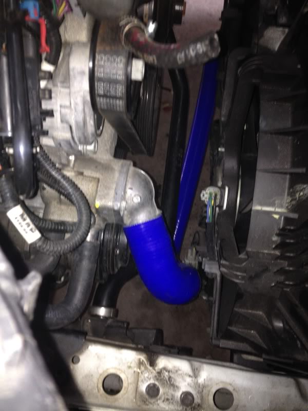
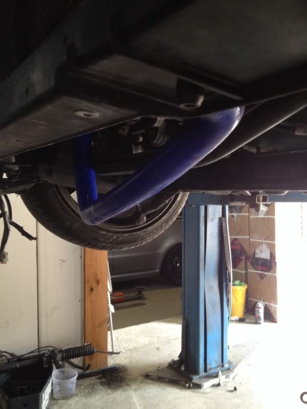
I cut the 6 inches off the vertical part of the pipe so it fits correctly above the sway bar.
I forgot to snap a picture of the heater lines, but the short of it is that the front port off the motor is plumbed to the left side of the bay as referenced from the rear of the car to the front. The the rear port is plumbed to the right side.
Up next is wiring... woohoo...
A couple details about using an aftermarket master cylinder. The mounting holes for the MC on the Z are offset by about 20 degrees from vertical. Most master cylinders have mounting holes that are vertical. To resolve this I made an adapter plate out of 1/4 inch aluminum. Fairly simple to do, just cut out the desired piece drill hold to put press in studs into for the MC to mount to and drill the holes for the bolts to go through the firewall.

Another note on the MC, you must have a 90 degree AN-3 fitting to come out of the MC, there is no room to have a an-3 to an-4 adapter and then a 90 degree fitting. after that I simply plumber it to the braided line on my hydraulic throw out bearing.
Up next was the cooling system. The LS motor has its coolant lines opposite to the Z. For the top radiator pipe it was simple, 2x 90 degree hoses and a 35mm pipe to connect them. The bottom however was a little more difficult. The engine side does not come out straight from the engine, its at a 45 degree angle from the engine. Luckily, I found that a 300ZX coolant line fits the angles, you simply have to cut a 6 inch straight section off to get the excess length taken care of. Here are photos of the 300ZX tubing.


I cut the 6 inches off the vertical part of the pipe so it fits correctly above the sway bar.
I forgot to snap a picture of the heater lines, but the short of it is that the front port off the motor is plumbed to the left side of the bay as referenced from the rear of the car to the front. The the rear port is plumbed to the right side.
Up next is wiring... woohoo...
 05-26-2014, 11:17 AM
#20
My last update was yesterday... not very patient are you haha.
No photos today, I installed the new gas pedal, The car is DBW and I was unable to use the 350Z pedal and sensor assy. I ran the ECU wiring into the cabin through the passenger side firewall and the OBD port and pedal wiring through the driver side.
No photos today, I installed the new gas pedal, The car is DBW and I was unable to use the 350Z pedal and sensor assy. I ran the ECU wiring into the cabin through the passenger side firewall and the OBD port and pedal wiring through the driver side.