When you click on links to various merchants on this site and make a purchase, this can result in this site earning a commission. Affiliate programs and affiliations include, but are not limited to, the eBay Partner Network.
What kind of wire loom is that? Did you actually cut and splice all the wires? Is that how you got shrink wrap around the ends to make it all super clean?
Removed each pin from the connector, put the braided loom over the wires, then put the heat shrink over it, then put the connector back on.
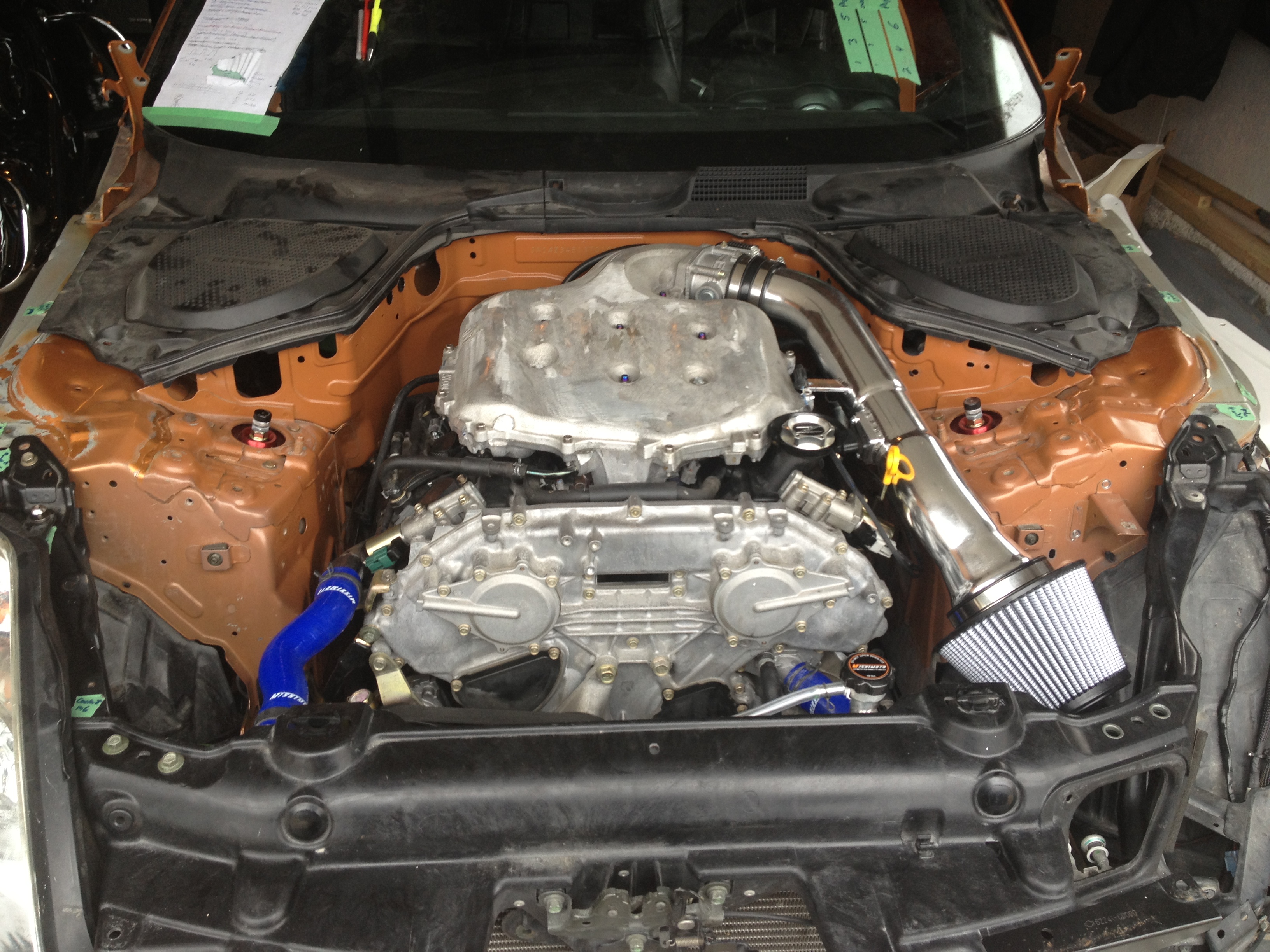
Engine bay still needs a ton of cutting, welding, shaving, polishing, painting etc. The mechanical/electrical aspect of it is done though.
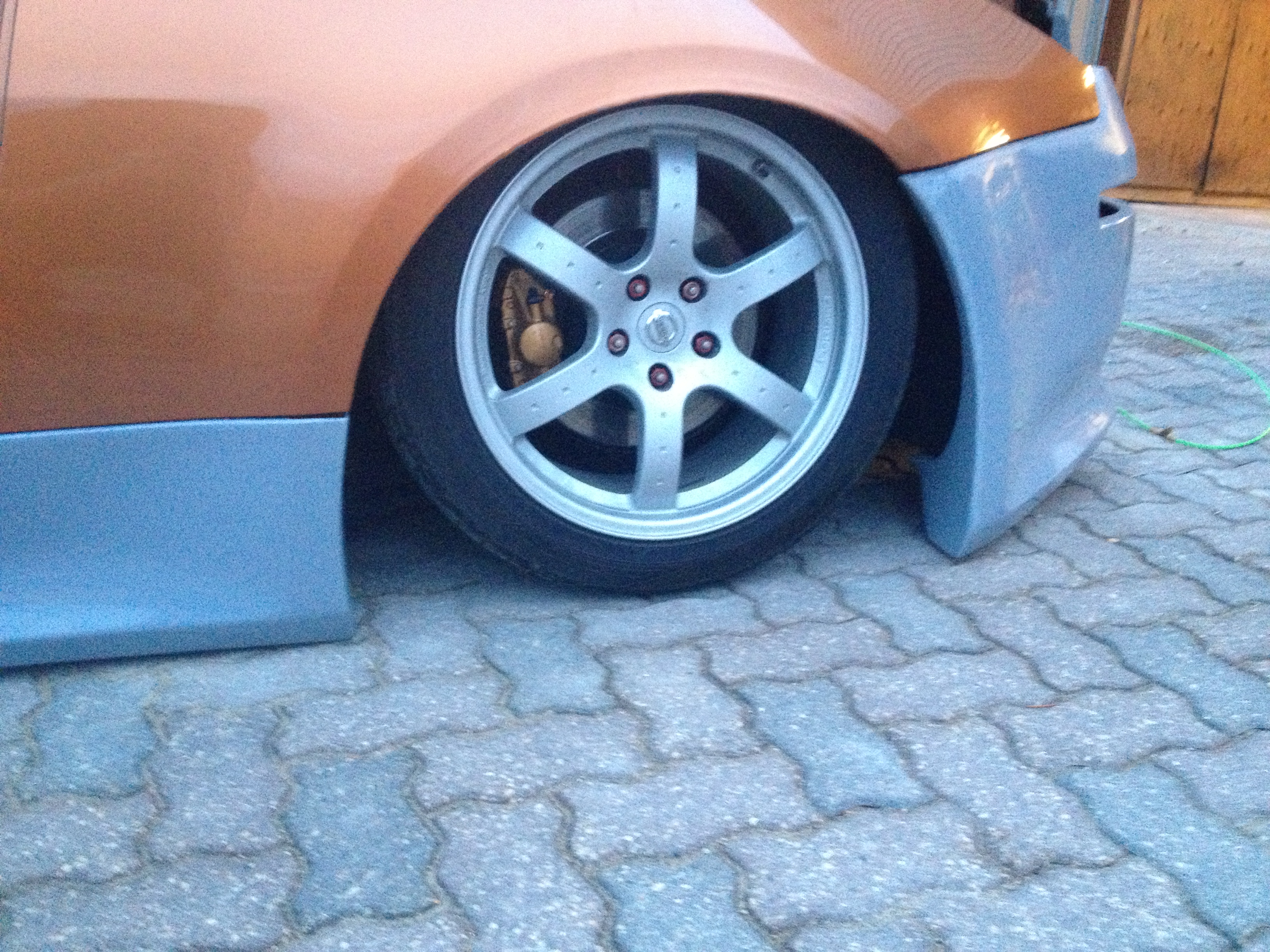
It's heading off to the body shop this week hopefully. Don't mind the fitment of the body panels, they're just quickly placed on the car. Final fitment will be significantly better.
Here is what I worked on over the weekend. Didn't get as far as I wanted to, but made progress none the less.
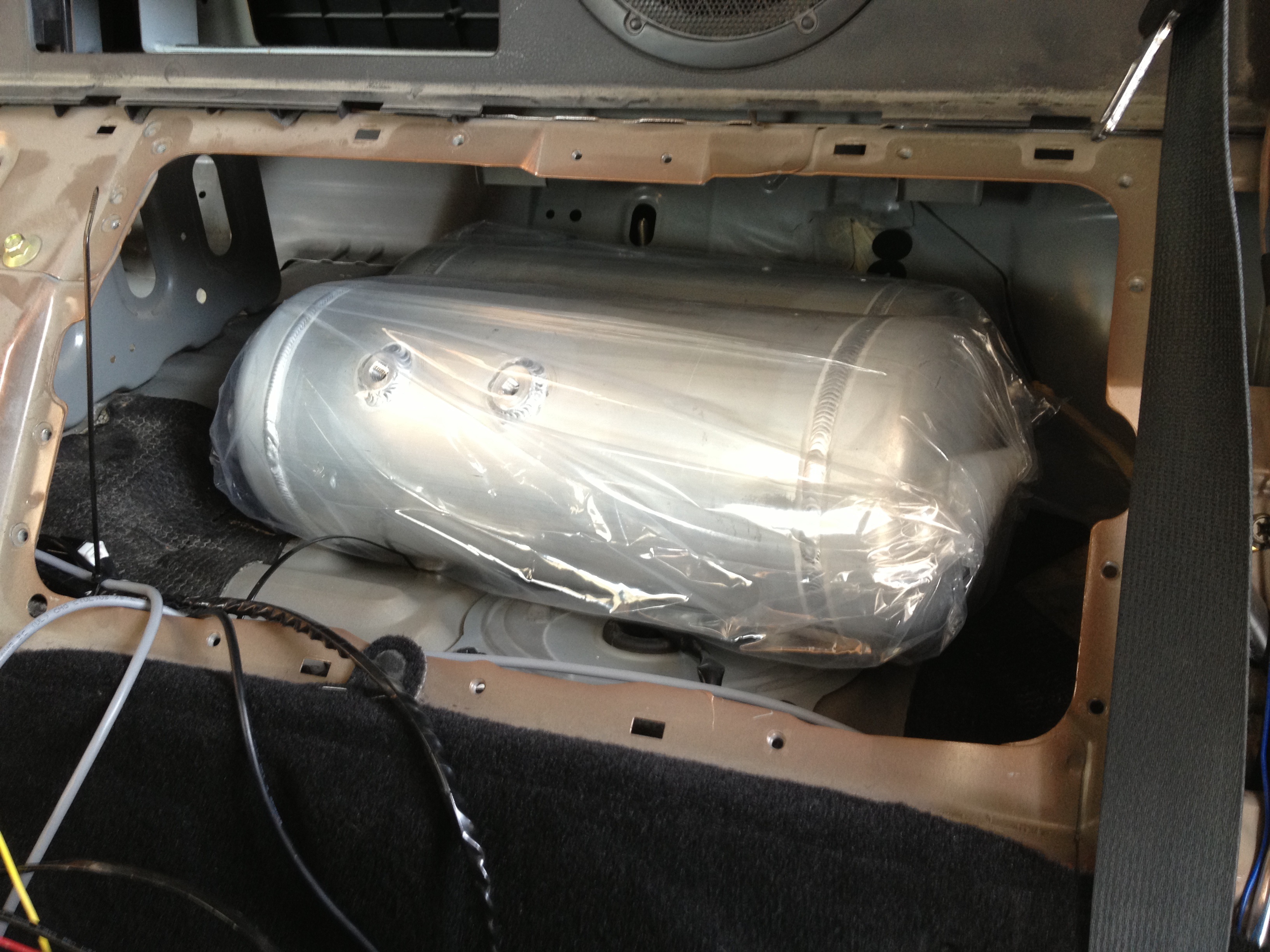
This is the empty cubby hole behind the driver's seat, opposite the passenger side glove box. Again, this is 100% empty, wasted space from factory. One main goal with the air install is to not lose any usable space. After some measurement I guessed that I could fit two 3 gallon tanks back there, I was right!
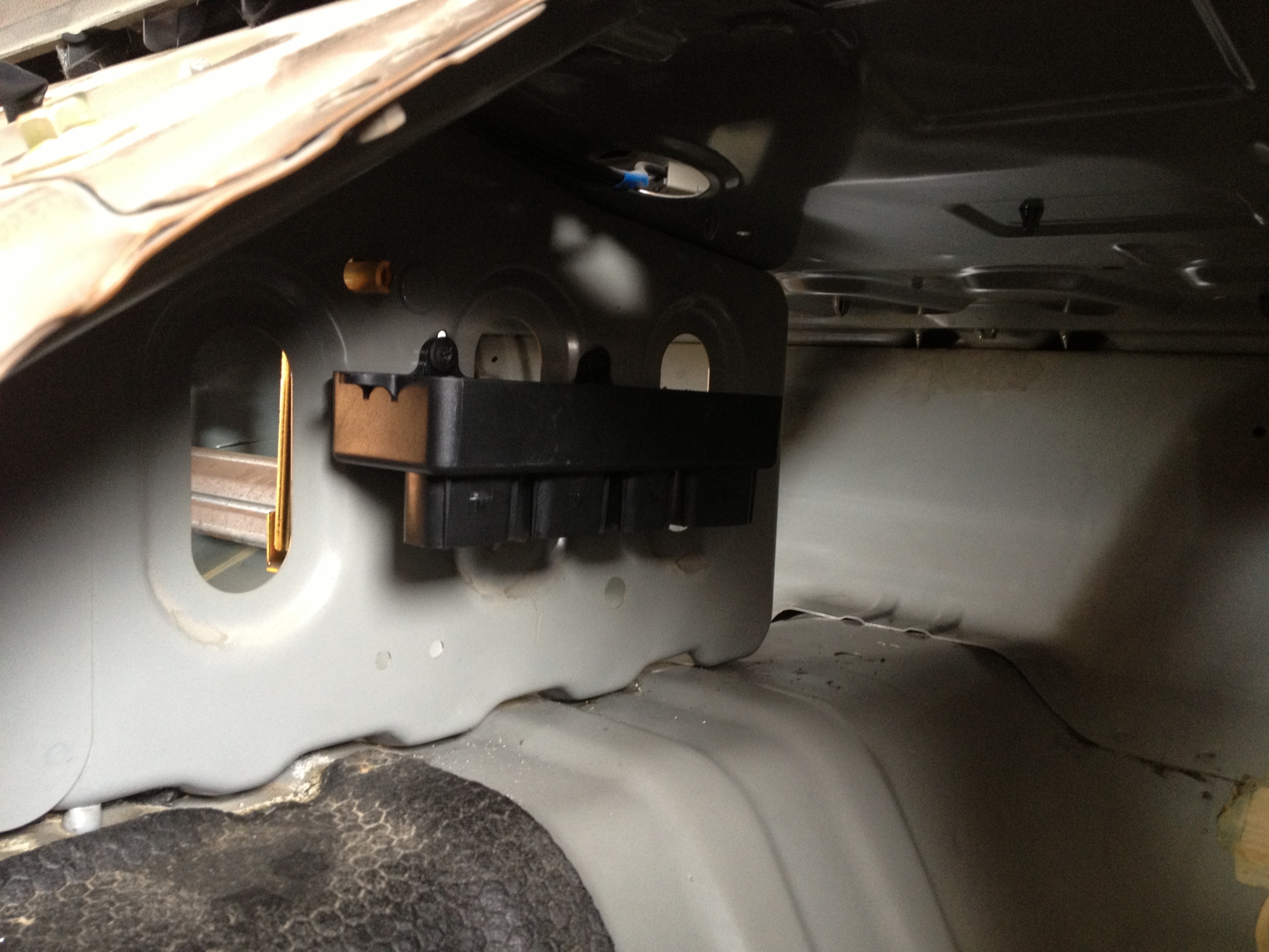
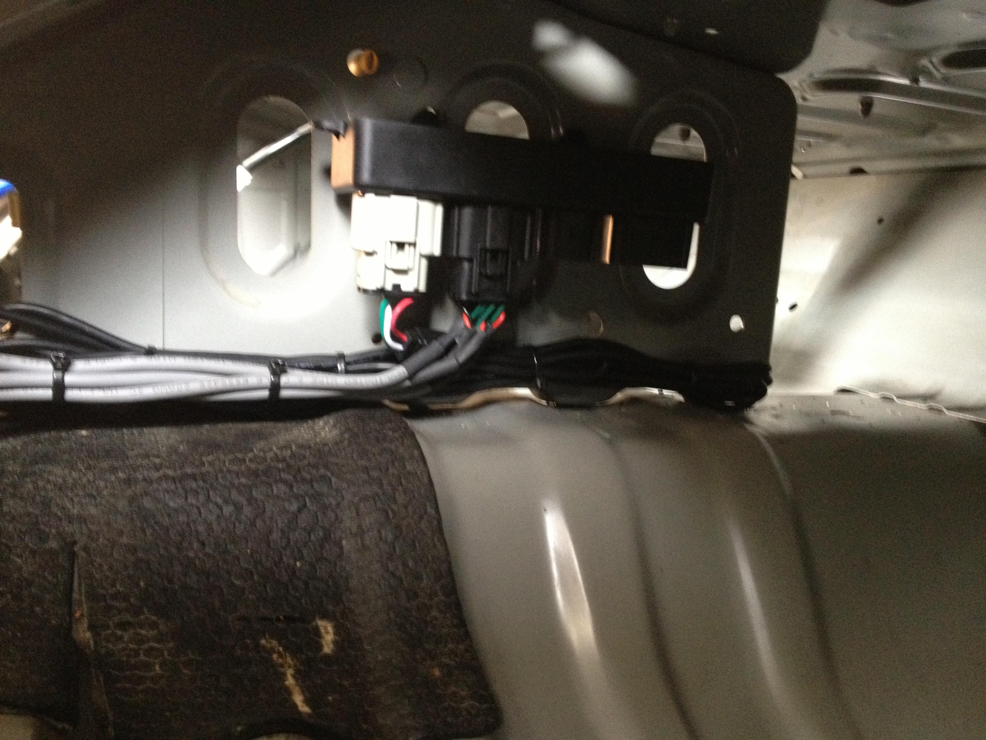
This is the Accuair control module mounted on the center divider between the passenger side and driver's side cubbies:
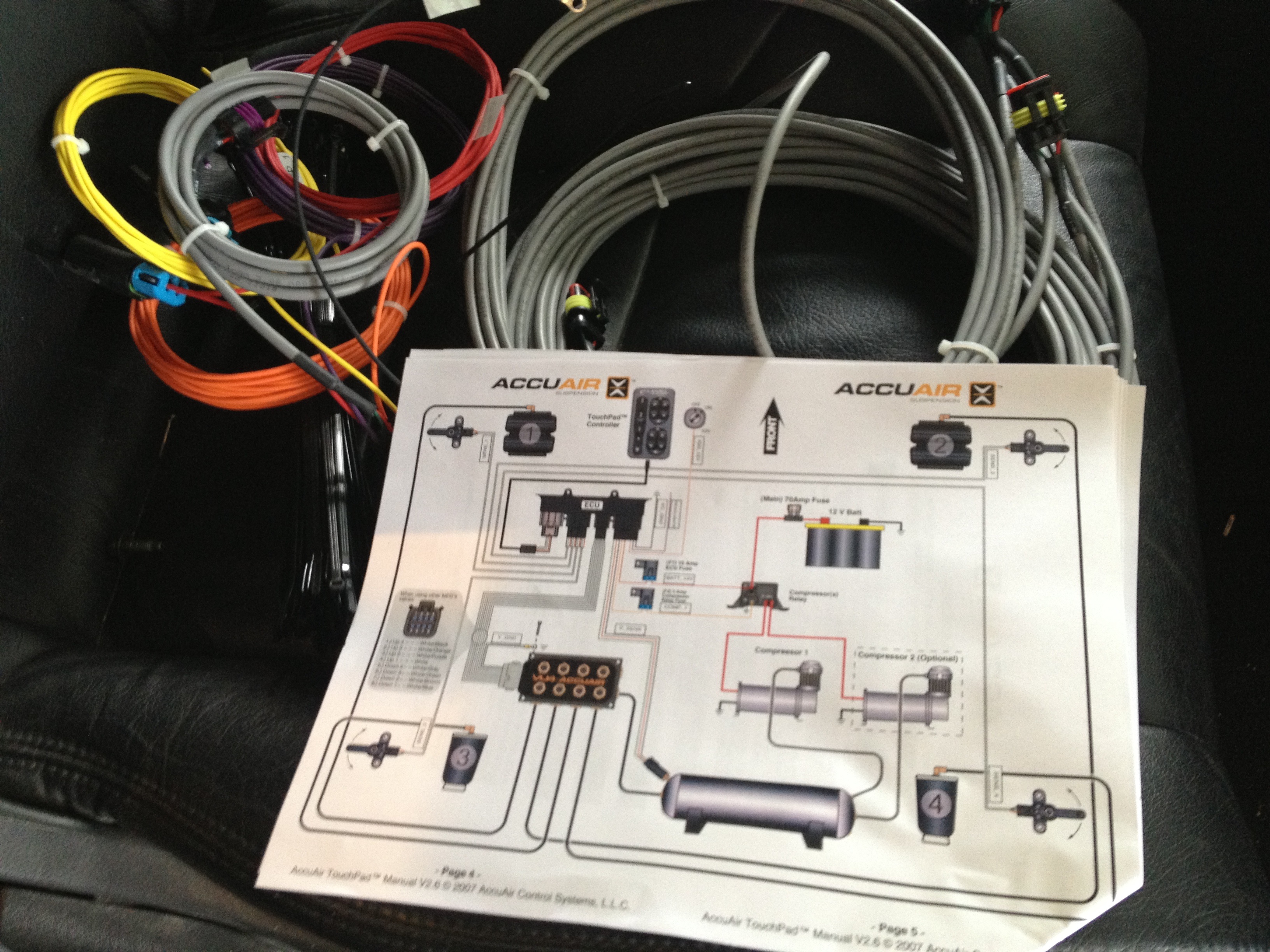
Started on the wiring. First connector on the left is the cable that goes to the touch pad controller, the second harness is the ride height sensors to each wheel.
Next up is the ride height sensors for the back wheels.
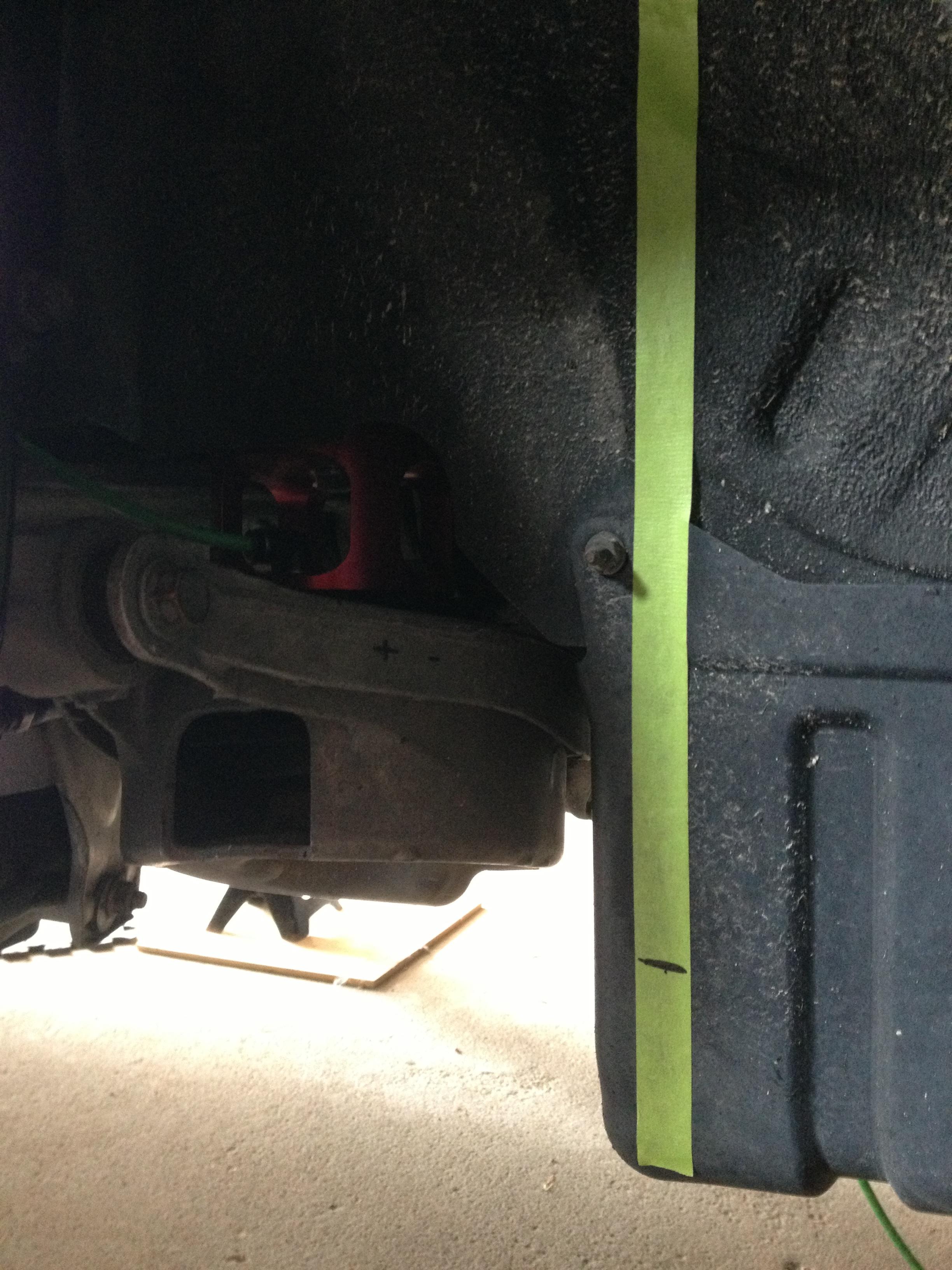
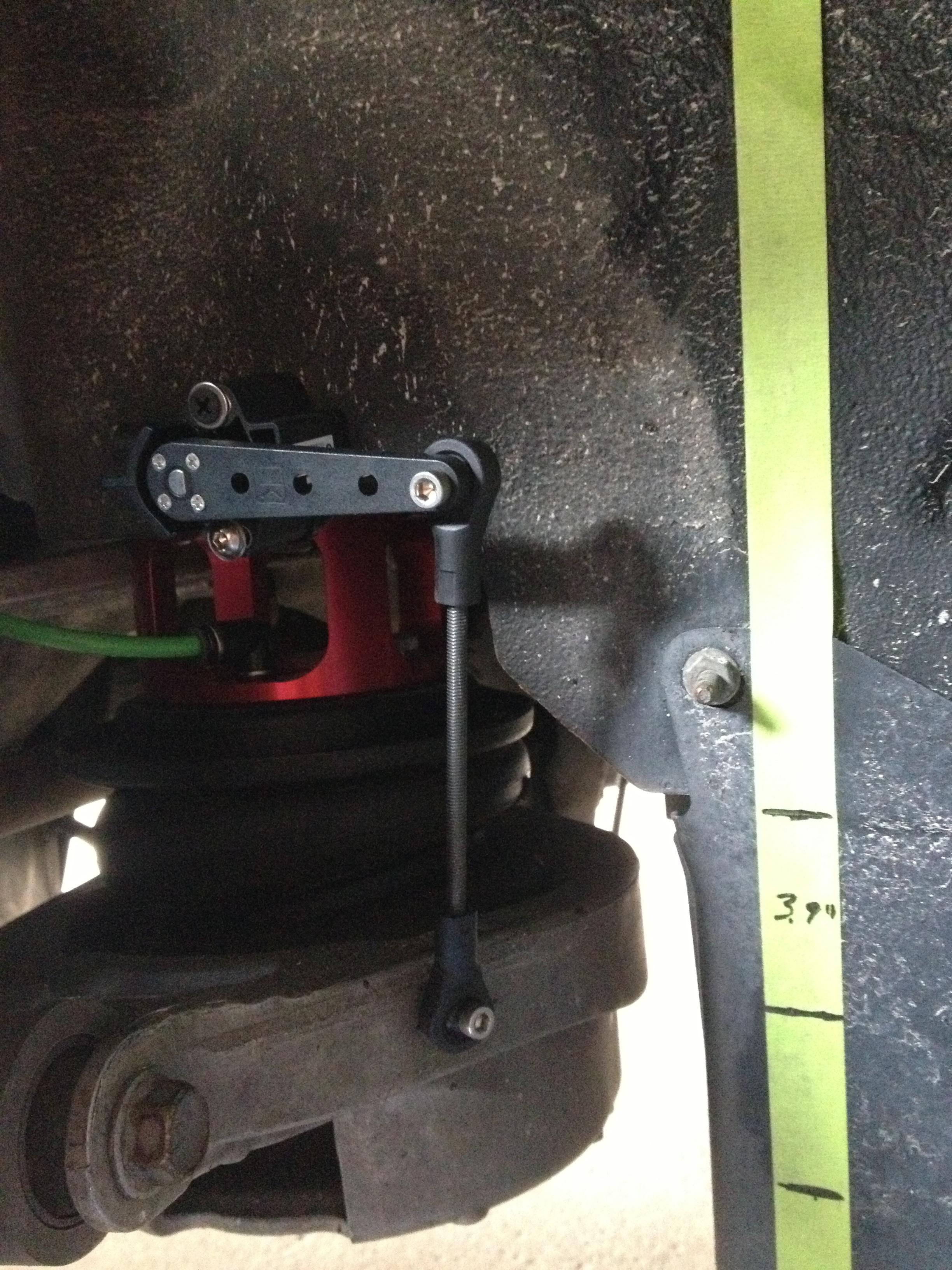
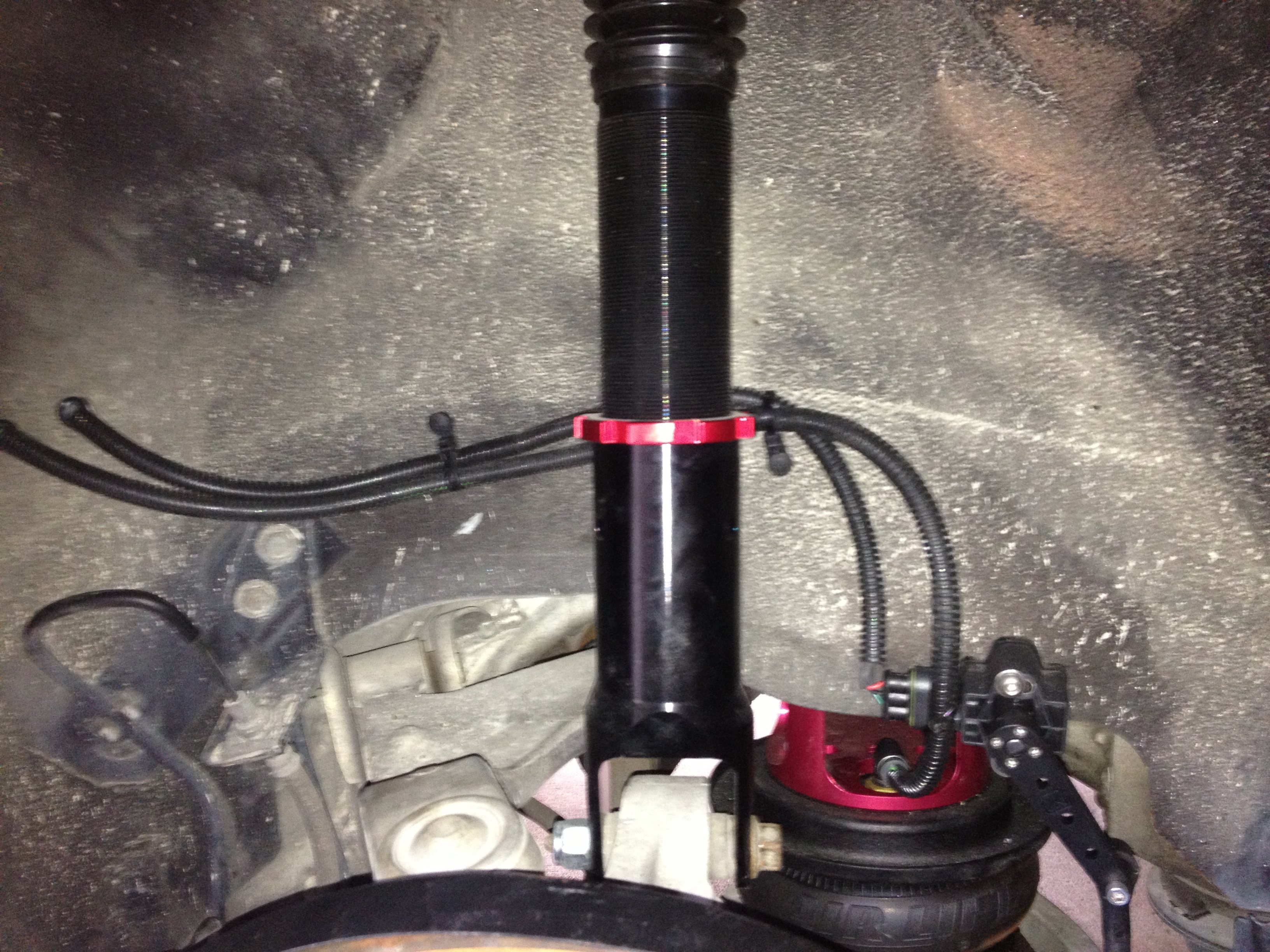
First thing to do is measure the travel of a specific point on the suspension. Note the + mark on the lower spring bucket, that was my point of reference for the measurements.
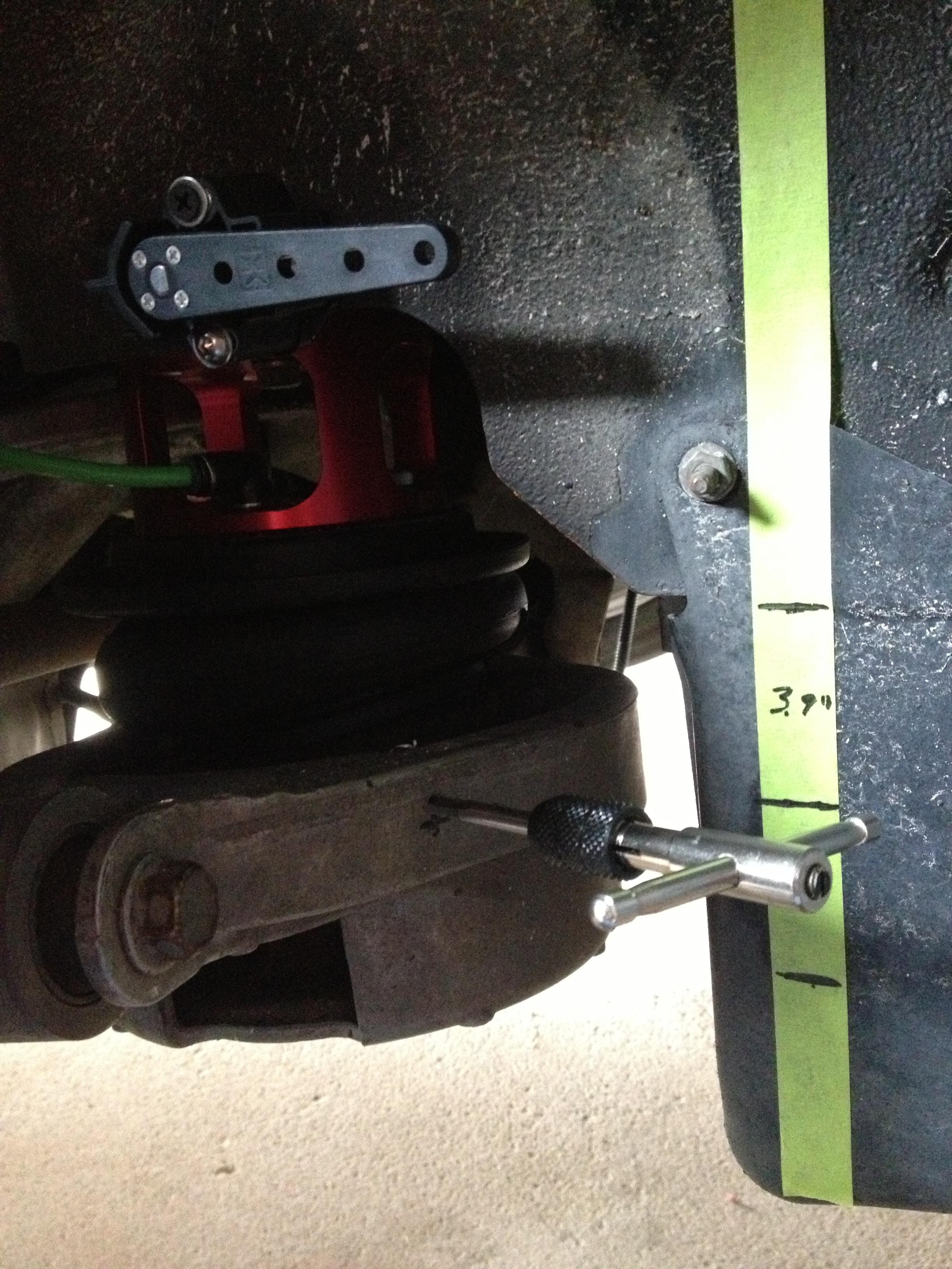
Skipped a couple steps, but here you see the mark on the tape for the top and bottom of the suspension travel as well as the center mark. I ended up with 3.9" travel at the point of reference on the suspension. This is just about perfect because Accuair wants 3-4" of travel. The closer to 4" that you get without going over 4" the better resolution you get. Not sure if it really matters much for this system, but being a control system engineer I know it's not a bad thing.
You can also see in this pic that I've drilled the lower arm and started to tap it. This is to attach the linkage for the ride height sensor.
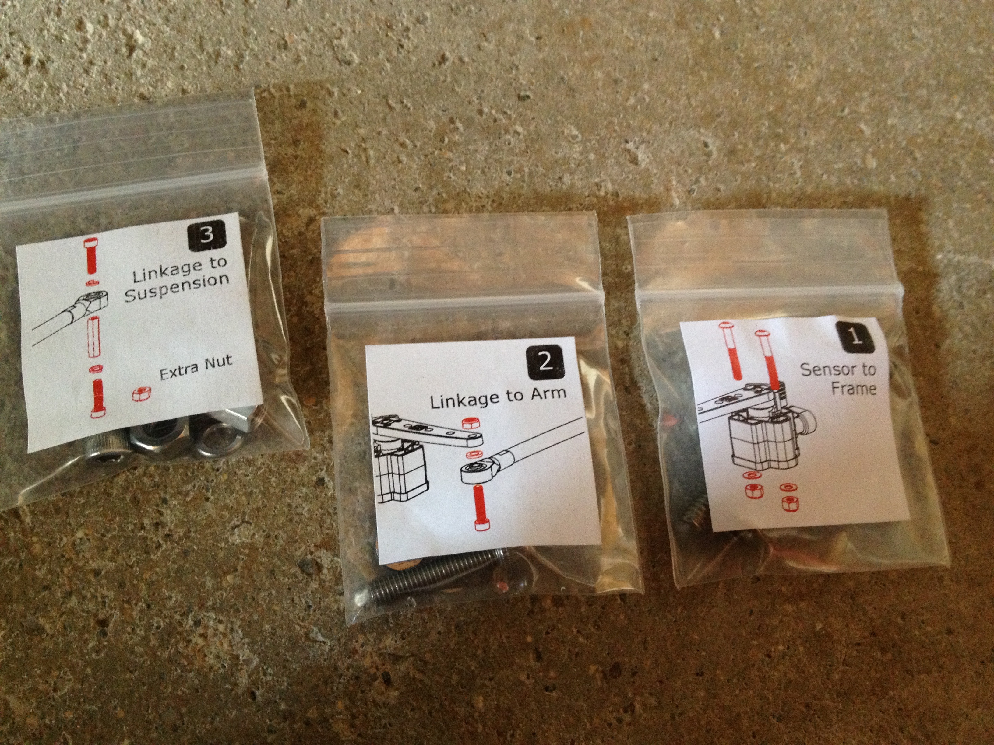
This is how Accuair packages their hardware, nice and organized. Almost idiot proof.
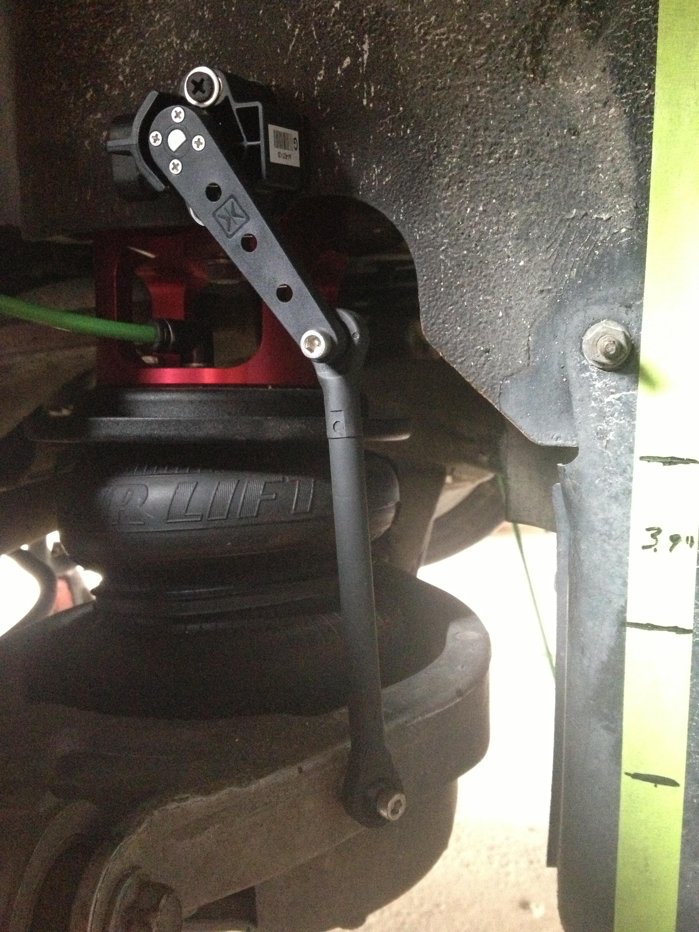
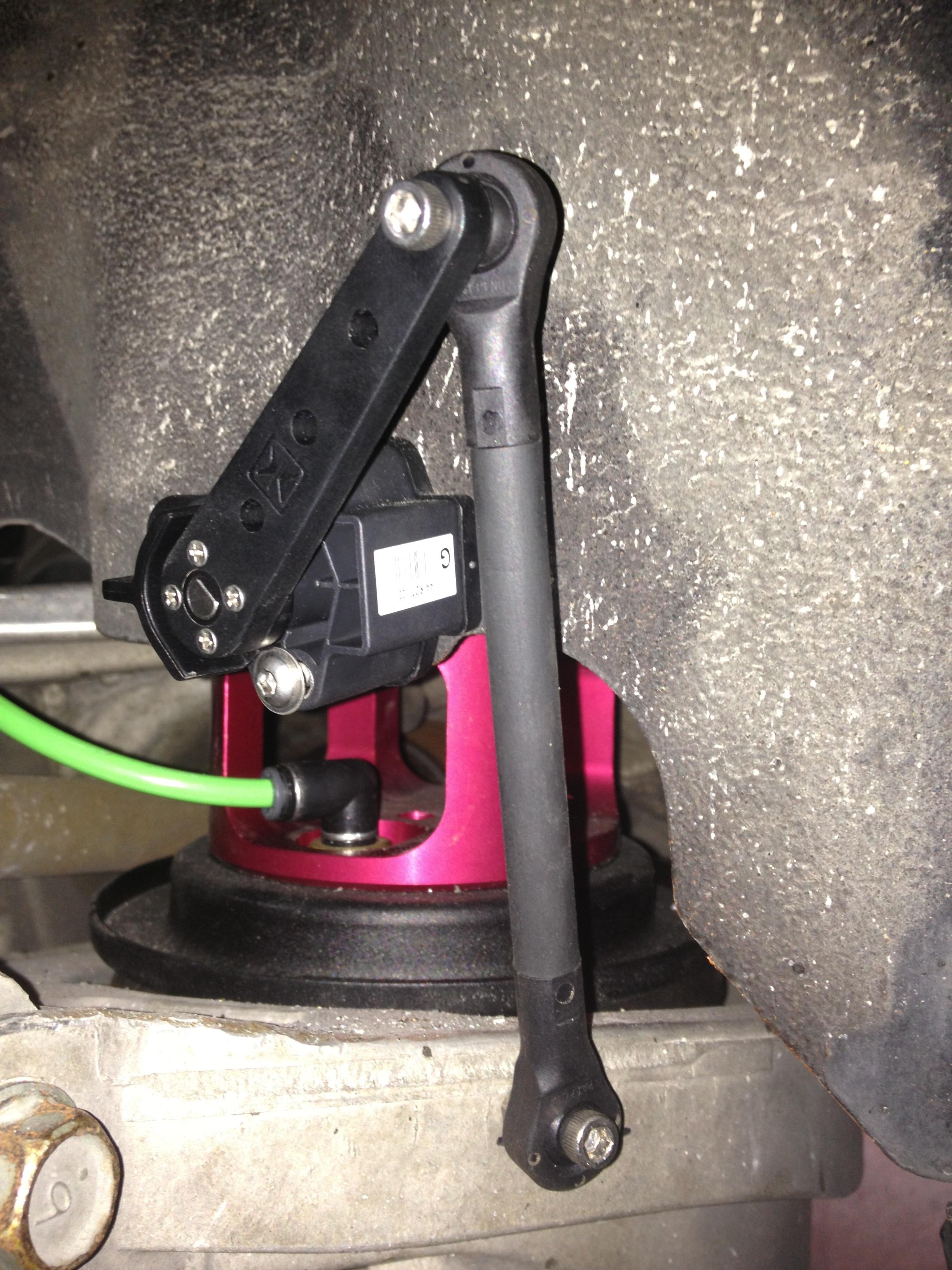
In this pic I've now rough fitted the ride height sensor and linkage. Had to cut the linkage rod down to length to get the ride height sensor centered with the suspension at the mid-point of its travel. I also cycled the suspension up and down a couple times to make sure there was no binding or interference.
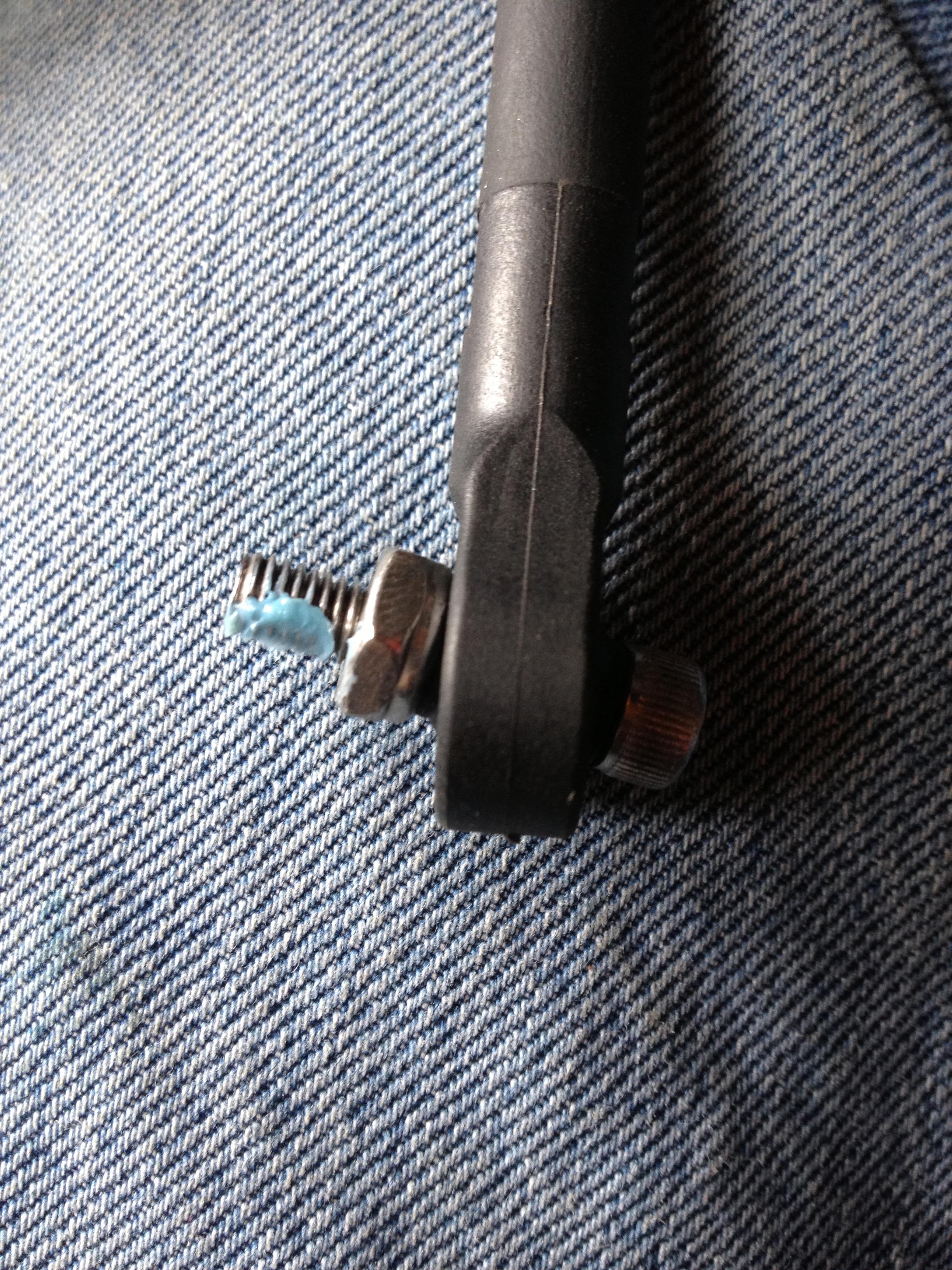
For the final install, I added a longer screw where the linkage mounts to the suspension. This allowed me to add a nut to space the linkage away from the suspension slightly to eliminate a bit of interference. Don't forget loctite for final installation!
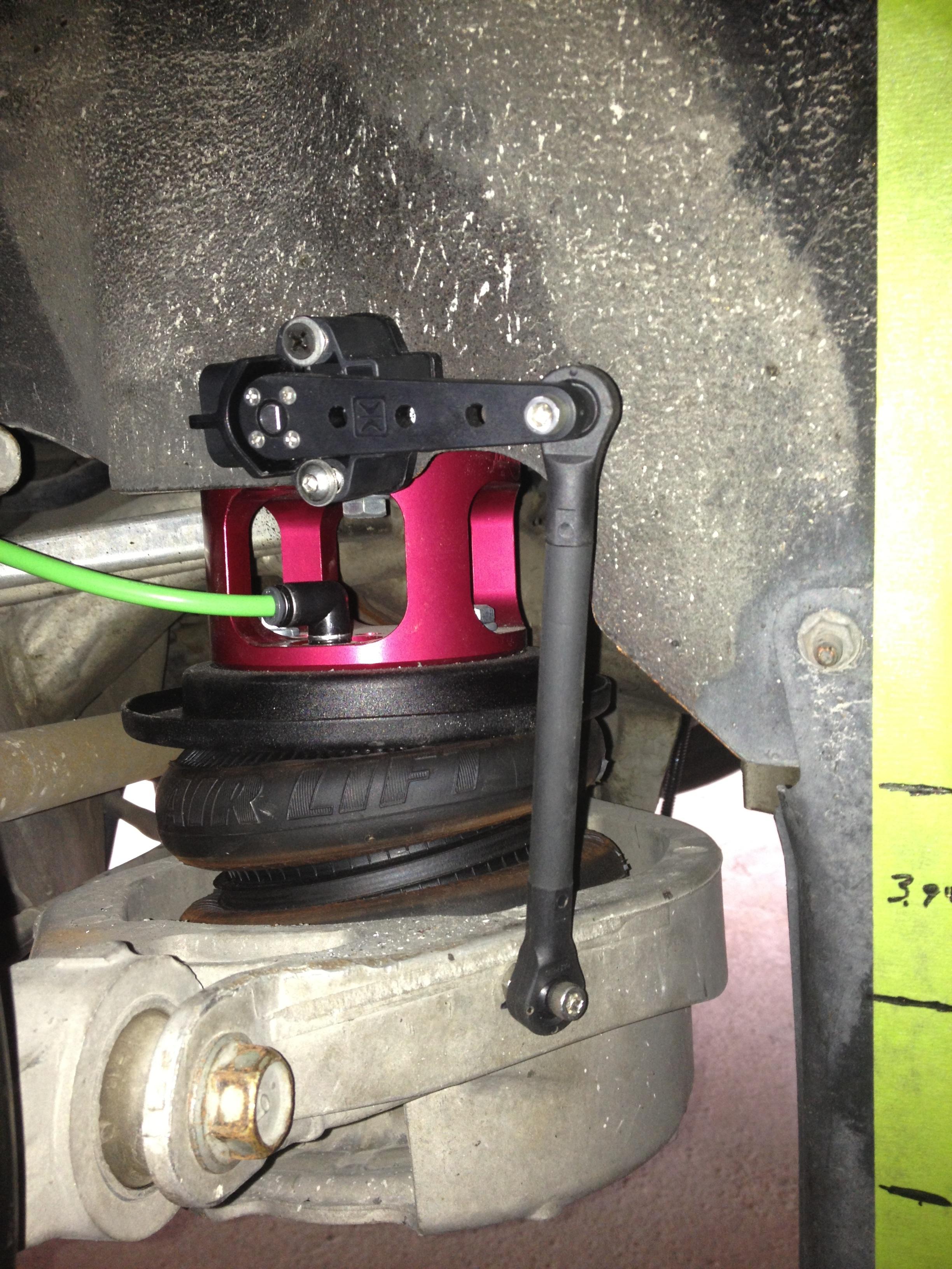
A few final test cycles of the suspension at full up, center and full down to make sure all is good.
And the final pic of the finished rear corner. Air line and wire harness run through rubber grommets into the cubby behind the drivers seat where the valve blocks and control unit are located.
No additional power was made with the filter off, car is makimg high570s low 580s constantly but the jacksahft is getting louder and louder. Im getting it towed home and replacing bearings myswlf si ce i cant afford anymore 130.00 hpur rate. New belt is great btw no slip
Enthusiast model... Has aftermarket z style vinyl covers over worn cloth... Kenwood double din unit, cross drilled slotted rotors... Got brushed stainless accent sheets with the car and installed some of them...
. Got an eBay OE style pre painted trunk spoiler...Love this machine...
Enthusiast model... Has aftermarket z style vinyl covers over worn cloth... Kenwood double din unit, cross drilled slotted rotors... Got brushed stainless accent sheets with the car and installed some of them...
. Got an eBay OE style pre painted trunk spoiler...Love this machine...
so you bump a 3 year old dead thread with your car that has nothing to do with the original post???

 10-31-2016, 12:51 PM