Crankcase Ventilation Mod w/Pics


 04-05-2010, 04:00 AM
#102
^ I've tried this and it worked for me for awhile but my built motor likely has more blow by than a stock motor. With Garrett turbos, one day you may wake up and find oil in your intercooler. That's when the hunt for optimizing the plumbing will ensue - that's what happened for me - one fine day the car started smoking. It seems Greddy turbos are somewhat less sensitive to crankcase pressure increase vs the Garrett fwiw.
In particular with the plenum port plugged off, you are seeing very little vacuum at idle/cruise - and you've got a lot of hose generating resistance for gases to escape. With a similar setup (but with a breather on the tubing also) but no plenum vacuum, I found I could get the system to work with no smoking, but I'd get black streaks out the back of the exhaust onto the ground during startup. I don't really understand why but I presume it had to do with a slow oil leak during idle when the car was parked, or during startup... Anyway, you may find a need to tweak your setup when you get your built motor installed.
From the catch can:
- 1 hose goes all the way around to the driver's side valve cover port.
- the other hose goes to a tee
-- one end of the tee is 3/8" in size and goes to the cosworth (check valve allowing air to LEAVE catch can)
-- other end of the tee is 1/2" and goes to the driver's side turbo intake (check valve allowing air to LEAVE catch can)
* I think this would work, perhaps even better, with the driver's side port plumbing and passenger PCV breather reversed, but I haven't had a chance to redo the plumbing and datalog it. The reason I did it this way is that the passenger PCV nipple points up and this prevents oil from dripping out of the breather, but rather drips back down into the valve cover. If you drill open the driver's side valve cover port, then it really doesn't matter which way you plumb it.
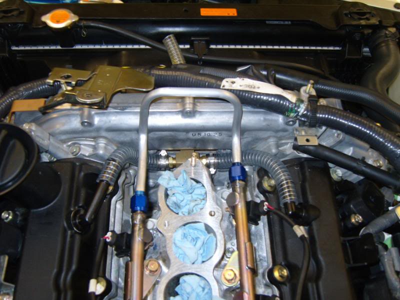
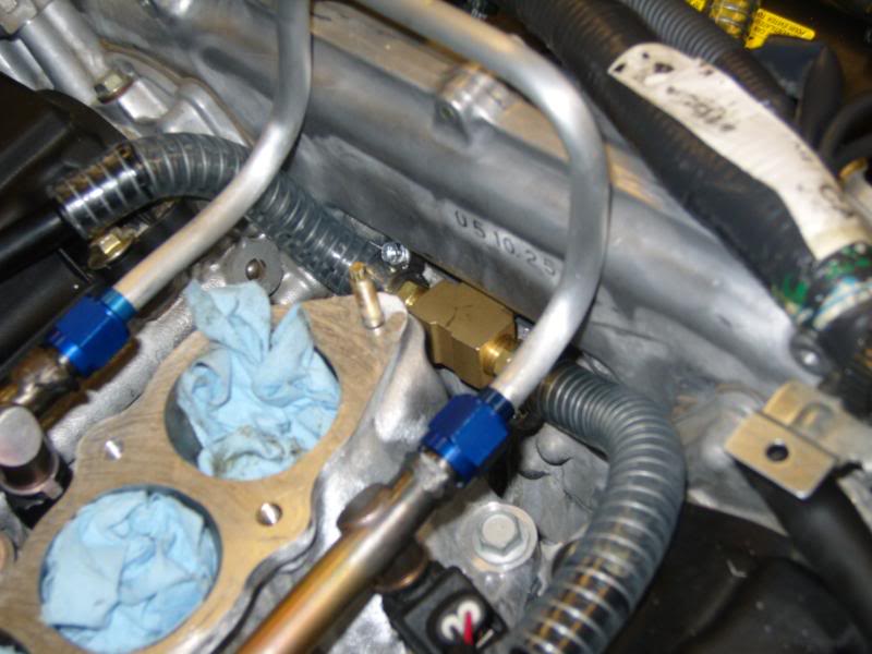
I attached a picture modified from above, so the positioning of the components is a little off, but you get the idea. When I datalogged crankcase pressure, I was actually measuring pressure in the catch can.
In particular with the plenum port plugged off, you are seeing very little vacuum at idle/cruise - and you've got a lot of hose generating resistance for gases to escape. With a similar setup (but with a breather on the tubing also) but no plenum vacuum, I found I could get the system to work with no smoking, but I'd get black streaks out the back of the exhaust onto the ground during startup. I don't really understand why but I presume it had to do with a slow oil leak during idle when the car was parked, or during startup... Anyway, you may find a need to tweak your setup when you get your built motor installed.
- 1 hose goes all the way around to the driver's side valve cover port.
- the other hose goes to a tee
-- one end of the tee is 3/8" in size and goes to the cosworth (check valve allowing air to LEAVE catch can)
-- other end of the tee is 1/2" and goes to the driver's side turbo intake (check valve allowing air to LEAVE catch can)
* I think this would work, perhaps even better, with the driver's side port plumbing and passenger PCV breather reversed, but I haven't had a chance to redo the plumbing and datalog it. The reason I did it this way is that the passenger PCV nipple points up and this prevents oil from dripping out of the breather, but rather drips back down into the valve cover. If you drill open the driver's side valve cover port, then it really doesn't matter which way you plumb it.
I attached a picture modified from above, so the positioning of the components is a little off, but you get the idea. When I datalogged crankcase pressure, I was actually measuring pressure in the catch can.
Last edited by rcdash; 04-05-2010 at 05:08 AM.
 04-05-2010, 07:14 AM
#105

Can you please draw the best setup for an NA motor on this diagram with the hoses, check valves and T fittings?


I have a filter here so no hose goes into the pipe.

The PCV gets clogged eventually so this mod will be needed regardless of the fact that you do not have issues with it now.
Last edited by Andrei; 04-05-2010 at 07:54 AM.
04-05-2010, 08:19 AM
#106
If wannabuy350z has a tight motor, he may not have excessive blow by, and may never have to change his setup.
For a stock (NA) setup, I would leave it stock. If the PCV valve clogs, it's a $15 part and 10 minutes to swap out. All of the above discussion is FI related. If you feel that blow by is excessive at idle while NA, then you can drill out the PCV and just route the nipple through a catch can and then to the manifold. Just to clarify, all of my data logging is on a built low compression motor that has increased clearances because of my Arias ED pistons. I would recommend putting a pressure gauge on your catch can and make sure you don't exceed 8 psi of vacuum or you'll be sucking oil out of the crankcase. You can use smaller hose with reducer fittings to lower vacuum if you need to.
Looking back over your posts, I think you may be confusing poor spark plug/valve cover gasket sealing with increased crankcase pressure. The two may not be necessarily related (unless you've noted increased pressure with a gauge?).
Last edited by rcdash; 04-05-2010 at 08:24 AM.

 04-13-2010, 09:16 AM
#109

Updating this thread after receiving a PM. The above worked but is overly complicated and not necessary (for me). I realized this by actually logging crankcase pressure (well catch can pressure actually). I was seeing crankcase pressure as high as 4 psi, running 15 psi of boost for less than 10 seconds, depending on various plumbing configurations! Read on for a method that minimizes this...
My current set up entails having a breather filter on the drilled out PCV nipple on the passenger side. This breather is designed to allow fresh air into the crankcase unless blow by is excessive (happens under extended boost conditions - I've data logged it!). The driver's side valve cover vent has a 1/2" heater hose connection that goes to my single greddy square catch can up front. That catch can is stuffed with a sponge to trap oil vapor and the outlet goes to a tee fitting. One end of the tee has a check valve and goes to the plenum port. The other end of the tee also has a check valve and goes to the driver's side turbo air intake piping (this is required for me because of my recirculating bov that dumps air into that tube on throttle lift).
This set up works well (crank case pressure reaches max 1 psi even with extended boost) and eliminates smoking issues I've had in the past. With the tubing and check valves I have in place I draw about 4-6 mm Hg (2-3 psi) of vacuum during idle, which helps to maintain piston ring seal during idle/low load conditions. I think the mirror image of my current set up will work also (swapping driver's side and passenger's side valve cover functions) but I haven't had a chance to actually test it and data log it. The size and length of tubing used has a direct impact on ability to evacuate crankcase pressure!
Please ignore my ignorance on this subject, but I have some questions regarding using a catch can with my new build. If I am understanding your description correctly (I may not be), you merely use a breather on the passenger side valve cover but a catch can on the driver side valve cover. Wouldn't you want to do both sides the same way, or does that have to due with your recirculating BOV?
EDIT: I just looked at the picture above. It does not look like the driver's side has the location to put the breather.
EDIT EDIT: I think Quadcam mentioned earlier in this thread the idea of using a breather on the catch can rather than running a hose back to the intake. Any issues with doing that? (Ninja edit, I just re-read that you have a check valve going to the plenum, which answers the question I previously posted here). Still, what about just putting a breather on the catch can output?
Last edited by ttg35fort; 04-13-2010 at 09:50 AM.
04-13-2010, 10:05 AM
#110

its not very complicated.
just plumb every vent on the heads together and have them being sucked on by the turbo inlet, which only can create vacuum.
there is no vacuum/boost being supplied by the plenum, thus no need for check valves and no way for boost to build since the PCV isnt tied to the plenum anymore
so..
2 to 4 vents on the heads > catch can >turbo inlet.
or
just put breathers on the head vents, have no chance for building crankcase pressure but lose the little bit of fume removal under light load since there is no vacuum source.
Last edited by str8dum1; 04-13-2010 at 10:09 AM.
04-13-2010, 10:22 AM
#111

its not very complicated.
just plumb every vent on the heads together and have them being sucked on by the turbo inlet, which only can create vacuum.
there is no vacuum/boost being supplied by the plenum, thus no need for check valves and no way for boost to build since the PCV isnt tied to the plenum anymore
so..
2 to 4 vents on the heads > catch can >turbo inlet.
or
just put breathers on the head vents, have no chance for building crankcase pressure but lose the little bit of fume removal under light load since there is no vacuum source.
just plumb every vent on the heads together and have them being sucked on by the turbo inlet, which only can create vacuum.
there is no vacuum/boost being supplied by the plenum, thus no need for check valves and no way for boost to build since the PCV isnt tied to the plenum anymore
so..
2 to 4 vents on the heads > catch can >turbo inlet.
or
just put breathers on the head vents, have no chance for building crankcase pressure but lose the little bit of fume removal under light load since there is no vacuum source.
04-13-2010, 10:27 AM
#112
^^^^^
Thanks, Rich!
One more question... How quickly does oil build up in the oil catch can?
I have the same one that Larry (JetPilot) has, but Roger seems to think it is too small. It is a tube about 2" OD/1.75" ID and 7.25" long. It seems like it should hold a reasonable amount of oil to me.
EDIT: I just measured the inside of it. the portion that holds the sponge hanges down roughly 3 inches into the can or so. It will hold about 200cc of oil before it needs to be drained. So I guess, the question is how frequently I will need to drain it? I see that Greddy makes a 500cc unit and a 1000cc unit. Obviously, those can go quite a bit longer before needing to be drained.
I just did a quick test on blowing air through it, and it seems to flow fine. The hose that came with it is far more restrictive than the catch can itself. It's about 4' long and maybe a 3/8" ID. So, I'm thinking the one I have will be fine if I use a larger hose, so long as I'm not having to drain it every 500 miles. I deally, I can just drain it each time I change my oil, say about every 3k miles or so. I just don't know if it will fill up faster than that.
Raj, how often are you having to drain your Greddy? Do you have the 500cc or 1000cc unit?
Last edited by ttg35fort; 04-13-2010 at 10:58 AM.
 04-13-2010, 10:58 AM
#114
depends how loose your build is. I didnt have any accumulation with my stock motor. With my new motor, I just have a hose coming off the drilled out pass PCV and I have drops on my garage floor. Its going to be worse when the car is cold.
200ml is quite a bit. thats a 1/4 of a qt of oil.
200ml is quite a bit. thats a 1/4 of a qt of oil.

 04-13-2010, 11:34 AM
#117
My goal has been to (A) create ventilation that pulls out blow by gases but leaves the oil in the crankcase as much as possible and (B) minimize crankcase pressure.
Not sure how big my catch can is, but it's not nearly full - have not had to empty it with my current set up, running since Jan. I have taken a peek inside and it currently contains a small amount of foul smelling oil laden with fuel. So I'm trapping mostly fuel vapor and not pulling out too much oil. This wasn't always the case though...
When I tapped into the central ports (that connect the two valve covers), I would pull back a lot more oil - an ounce or so a day I would say of daily driving. I think those ports are not baffled as well as either the passenger or driver's side vents. The setup posted by Boosted Performance above may work for stock motors, but I think it will drip too much oil on a built (loose) motor. So I reconnected those to each other and took them out of the catch can circuit. I have a breather on the passenger side and pull from the driver's side. When I boost continuously my breather filter saturates with oil but does not drip because it faces straight down back into the crankcase on the passenger side nipple.
I may switch and put the breather on the rear driver's side port and draw suction from the passenger side port to (A) hide the breather for emissions testing purposes and (B) shorten the plumbing going to my catch can up front. The length and diameter of the hosing matters! Too small, and you create a restriction to gas escape, which can lead to build up of crankcase pressure under extended boost, which leads to oil seeping past turbo seals, etc. A breather right on the valve cover is a nice "safety" to preclude this from happening despite the rest of the plumbing.
Last edited by rcdash; 04-13-2010 at 11:36 AM.
04-13-2010, 11:40 AM
#118
My goal has been to (A) create ventilation that pulls out blow by gases but leaves the oil in the crankcase as much as possible and (B) minimize crankcase pressure.
Not sure how big my catch can is, but it's not nearly full - have not had to empty it with my current set up, running since Jan. I have taken a peek inside and it currently contains a small amount of foul smelling oil laden with fuel. So I'm trapping mostly fuel vapor and not pulling out too much oil. This wasn't always the case though...
When I tapped into the central ports (that connect the two valve covers), I would pull back a lot more oil - an ounce or so a day I would say of daily driving. I think those ports are not baffled as well as either the passenger or driver's side vents. The setup posted by Boosted Performance above may work for stock motors, but I think it will drip too much oil on a built (loose) motor. So I reconnected those to each other and took them out of the catch can circuit. I have a breather on the passenger side and pull from the driver's side. When I boost continuously my breather filter saturates with oil but does not drip because it faces straight down back into the crankcase on the passenger side nipple.
I may switch and put the breather on the rear driver's side port and draw suction from the passenger side port to (A) hide the breather for emissions testing purposes and (B) shorten the plumbing going to my catch can up front. The length and diameter of the hosing matters! Too small, and you create a restriction to gas escape, which can lead to build up of crankcase pressure under extended boost, which leads to oil seeping past turbo seals, etc. A breather right on the valve cover is a nice "safety" to preclude this from happening despite the rest of the plumbing.
Not sure how big my catch can is, but it's not nearly full - have not had to empty it with my current set up, running since Jan. I have taken a peek inside and it currently contains a small amount of foul smelling oil laden with fuel. So I'm trapping mostly fuel vapor and not pulling out too much oil. This wasn't always the case though...
When I tapped into the central ports (that connect the two valve covers), I would pull back a lot more oil - an ounce or so a day I would say of daily driving. I think those ports are not baffled as well as either the passenger or driver's side vents. The setup posted by Boosted Performance above may work for stock motors, but I think it will drip too much oil on a built (loose) motor. So I reconnected those to each other and took them out of the catch can circuit. I have a breather on the passenger side and pull from the driver's side. When I boost continuously my breather filter saturates with oil but does not drip because it faces straight down back into the crankcase on the passenger side nipple.
I may switch and put the breather on the rear driver's side port and draw suction from the passenger side port to (A) hide the breather for emissions testing purposes and (B) shorten the plumbing going to my catch can up front. The length and diameter of the hosing matters! Too small, and you create a restriction to gas escape, which can lead to build up of crankcase pressure under extended boost, which leads to oil seeping past turbo seals, etc. A breather right on the valve cover is a nice "safety" to preclude this from happening despite the rest of the plumbing.
04-13-2010, 11:49 AM
#119
The one that goes from the driver's side rear port all the way to the front is 5/8". Then it narrows going to the catch can to 1/2" for the last 12" or so. The hose drawing vacuum during idle from the manifold is 3/8" and with the check valve in place, it draws 2 psi of vacuum (4 mm Hg) at idle in the catch can, which seems reasonable.
I tried an experiment with no use of the intake manifold for vacuum. I had a breather hose going from 5/8" the driver's side port to the turbo intake (like stock as well as with a catch can in between). The passenger side PCV nipple was drilled out, and 3/8" hose went to a catch can, then another 3/8" hose leading to the wheel well with a breather filter. No check valves - completely open system - and my intercooler filled with oil. I changed the PCV side to 1/2" - still got some oil. Changed to 5/8" and shortened the hose and got no more leaking that I could tell. BUT with no intake manifold vacuum at idle, I would get these black streaks shoot out on start up. So maybe some oil was seeping past the rings on cranking??? Anyway, puting the intake manifold back into the circuit to generate vacuum at idle fixed that issue like magic.
Sorry for the verbose, meandering post... It's hard to summarize all the combinations I have tried. If you can, log crankcase pressure and then try different configurations to find the best set up for your engine.
I tried an experiment with no use of the intake manifold for vacuum. I had a breather hose going from 5/8" the driver's side port to the turbo intake (like stock as well as with a catch can in between). The passenger side PCV nipple was drilled out, and 3/8" hose went to a catch can, then another 3/8" hose leading to the wheel well with a breather filter. No check valves - completely open system - and my intercooler filled with oil.
I changed the PCV side to 1/2" - still got some oil. Changed to 5/8" and shortened the hose and got no more leaking that I could tell. BUT with no intake manifold vacuum at idle, I would get these black streaks shoot out on start up. So maybe some oil was seeping past the rings on cranking??? Anyway, puting the intake manifold back into the circuit to generate vacuum at idle fixed that issue like magic.Sorry for the verbose, meandering post... It's hard to summarize all the combinations I have tried. If you can, log crankcase pressure and then try different configurations to find the best set up for your engine.
Last edited by rcdash; 04-13-2010 at 11:54 AM.
