Boosted Performance single turbo fabrication
 04-08-2012, 05:28 PM
#1

I have recently been presented with the opportunity to develop a single turbo kit for the 370z, and this project is now underway.
This will be a complete bolt on kit, with minimal modifications made to the car. The idea is to build a kit that can be installed by anybody with some basic knowledge and mechanical amplitude. As with the mid-mount kit, I hope to have most of my customers do the install themselves. The most difficult part of the install may be the removal of OEM catalytic converters..and let�s face it that is a rather easy task.
The kit will consist of the best components on the market, and will include:
Precision T4 6266 CEA billet turbo (or the 6766 CEA billet turbo as an option)
Tial Q BOV�s
Tial MV-S wastegates
Large vertical flow intercooler 25"x9"x3.5" core capable of 1950cfm of flow
Exa scavenge pump
Uprev Osiris tuner
340lph fuel pump
750cc Bosch EV14 Plug�n play fuel injectors
Complete oil cooler kit (since it is needed on these cars anyway)
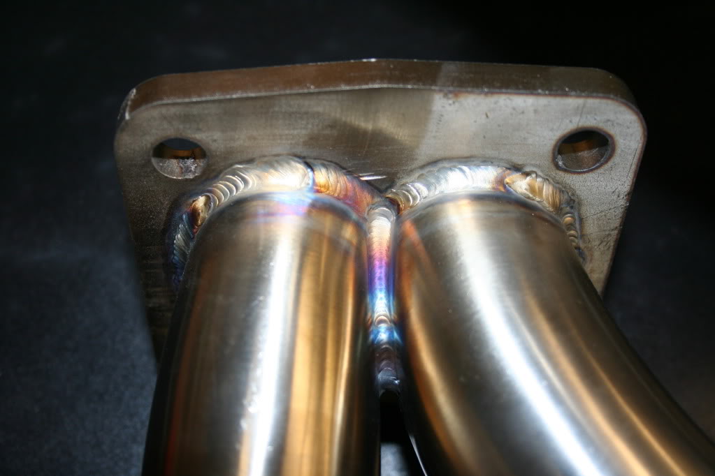
All 304 stainless exhaust, tig welded and back purged
Tig welded aluminum intercooler piping
All brackets (pump, fmic�ect) will be 304 stainless
3-ply silicone couplers
Stainless T-bolt clamps
This will also be a true twin scroll setup, where the firing order (pulses) of the VQ will be utilized. This is the ideal single turbo configuration, and the most efficient one. It also offeres the large T4 turbine to breathe, up to 1.32 a/r turbines. Testing on the 350z shows that if you want to go big on power, a small turbine can be a restriction. Sure the turbo (compressor) can make 700hp, but if you have a small turbine...you will not come even close to that.
I have recently built the first kit twin scroll turbo kit for a 350z, and here is how it turned out:
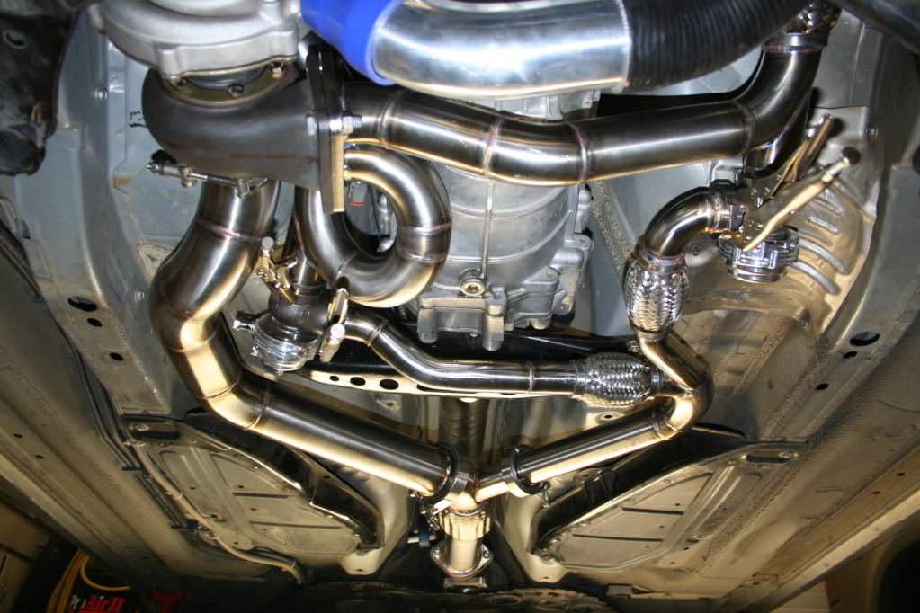
Twin scroll T4:
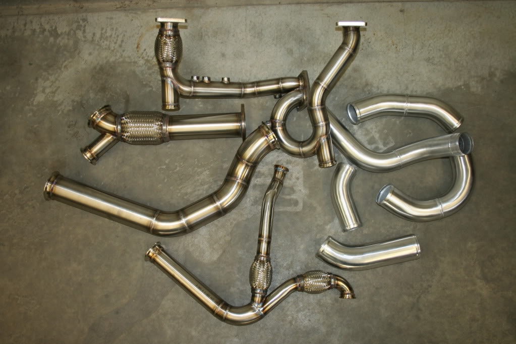
Piping before shipping:
The kit/design for the 370z will be the same, with simmilar pipe routing.
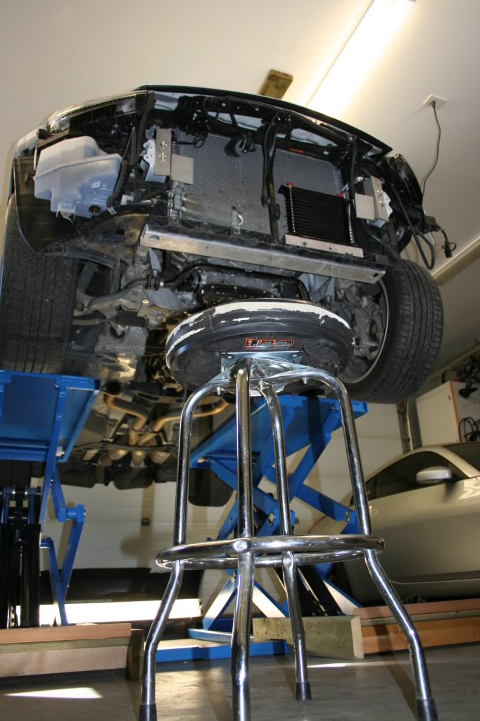
The car is currently on the lift, and I am about to install the intercooler. This thread will be updated, and have a lot of pictures posted.
This will be a complete bolt on kit, with minimal modifications made to the car. The idea is to build a kit that can be installed by anybody with some basic knowledge and mechanical amplitude. As with the mid-mount kit, I hope to have most of my customers do the install themselves. The most difficult part of the install may be the removal of OEM catalytic converters..and let�s face it that is a rather easy task.
The kit will consist of the best components on the market, and will include:
Precision T4 6266 CEA billet turbo (or the 6766 CEA billet turbo as an option)
Tial Q BOV�s
Tial MV-S wastegates
Large vertical flow intercooler 25"x9"x3.5" core capable of 1950cfm of flow
Exa scavenge pump
Uprev Osiris tuner
340lph fuel pump
750cc Bosch EV14 Plug�n play fuel injectors
Complete oil cooler kit (since it is needed on these cars anyway)
All 304 stainless exhaust, tig welded and back purged
Tig welded aluminum intercooler piping
All brackets (pump, fmic�ect) will be 304 stainless
3-ply silicone couplers
Stainless T-bolt clamps
This will also be a true twin scroll setup, where the firing order (pulses) of the VQ will be utilized. This is the ideal single turbo configuration, and the most efficient one. It also offeres the large T4 turbine to breathe, up to 1.32 a/r turbines. Testing on the 350z shows that if you want to go big on power, a small turbine can be a restriction. Sure the turbo (compressor) can make 700hp, but if you have a small turbine...you will not come even close to that.
I have recently built the first kit twin scroll turbo kit for a 350z, and here is how it turned out:
Twin scroll T4:
Piping before shipping:
The kit/design for the 370z will be the same, with simmilar pipe routing.
The car is currently on the lift, and I am about to install the intercooler. This thread will be updated, and have a lot of pictures posted.
 04-08-2012, 05:31 PM
#2
Day two of the build:
There was a lot of time spent here (on my �thinking chair�):
I am trying to figure out the best possible way to get the 2.5� aluminum piping from the turbo compressor to the intercooler, and it is a bit of a PITA. The reason for that is that I am trying to leave everything on the car as is, no moving of sensor wires (clips) no trimming plastic, as non invasive as possible.
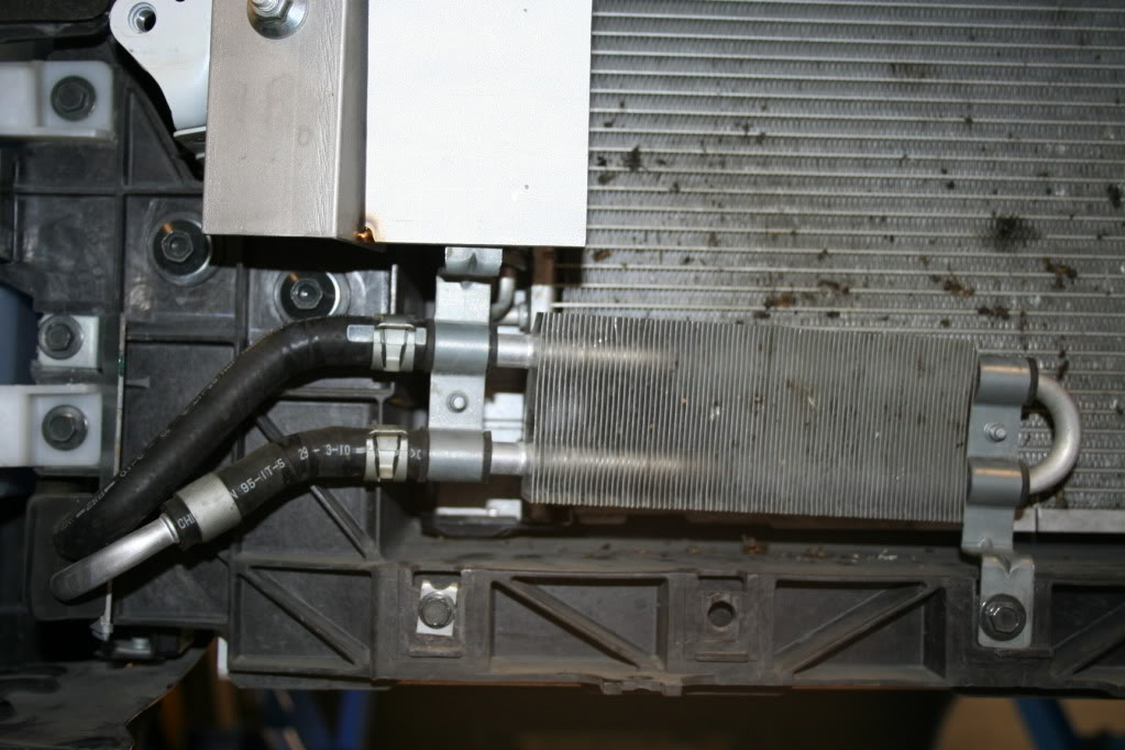
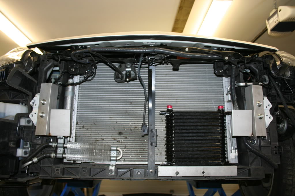
I did however manage to find the final resting spot for the PS cooler and the oil cooler. As with the rest, there is no need to open the lines and drain anything, just a simple flip of the bracket on the right hand side of the cooler:
Oil cooler is rather simple and straight forward. No magic here:
I did manage to pull the aftermarket headers off the car, and install the OEM�s. This was mainly due to this eventually becoming a production kit. With OEM headers I know that they are perfect, and will be in the same spot on every car. I have noticed that aftermarket headers can differ, and the three bolt flange can either be more forward, or back of where the OEM would be. Same goes for the angle of the flange�you just never know. When they are built, the welding (heat) makes them shrink and move around.
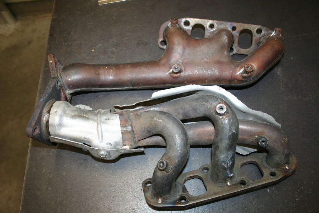
While on the topic of headers, since I have a 350z, I wanted you guys to see how different these manifold really are. It is obvious that there is a huge difference, and that Nissan realized that the 370z should get some decent manifolds
This is where you will see a huge difference in performance, as you can see the 350z header has an outlet of only 1.65� and when throwing boost in to the mix, that is very small:
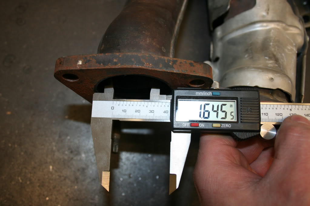
Now the 370z exhaust manifold at 2.2�:
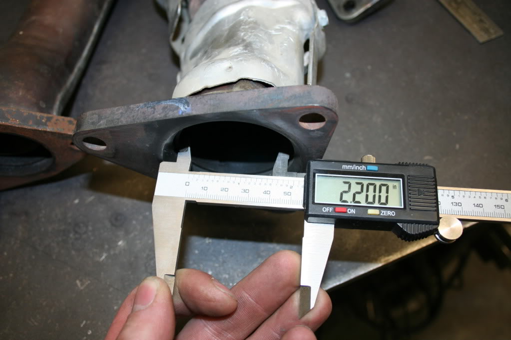
That is a 50% increase in cross sectional area, and a significant increase of flow.
Side by side:
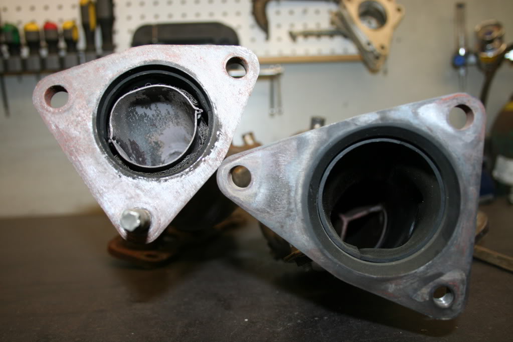
IMO the OEM exhaust manifold are well built, large enough, and there is no need to ever upgrade to aftermarket. I really don't think there is much to gain (if anythig at all).
There was a lot of time spent here (on my �thinking chair�):
I am trying to figure out the best possible way to get the 2.5� aluminum piping from the turbo compressor to the intercooler, and it is a bit of a PITA. The reason for that is that I am trying to leave everything on the car as is, no moving of sensor wires (clips) no trimming plastic, as non invasive as possible.
I did however manage to find the final resting spot for the PS cooler and the oil cooler. As with the rest, there is no need to open the lines and drain anything, just a simple flip of the bracket on the right hand side of the cooler:
Oil cooler is rather simple and straight forward. No magic here:
I did manage to pull the aftermarket headers off the car, and install the OEM�s. This was mainly due to this eventually becoming a production kit. With OEM headers I know that they are perfect, and will be in the same spot on every car. I have noticed that aftermarket headers can differ, and the three bolt flange can either be more forward, or back of where the OEM would be. Same goes for the angle of the flange�you just never know. When they are built, the welding (heat) makes them shrink and move around.
While on the topic of headers, since I have a 350z, I wanted you guys to see how different these manifold really are. It is obvious that there is a huge difference, and that Nissan realized that the 370z should get some decent manifolds
This is where you will see a huge difference in performance, as you can see the 350z header has an outlet of only 1.65� and when throwing boost in to the mix, that is very small:
Now the 370z exhaust manifold at 2.2�:
That is a 50% increase in cross sectional area, and a significant increase of flow.
Side by side:
IMO the OEM exhaust manifold are well built, large enough, and there is no need to ever upgrade to aftermarket. I really don't think there is much to gain (if anythig at all).
 04-08-2012, 05:32 PM
#4
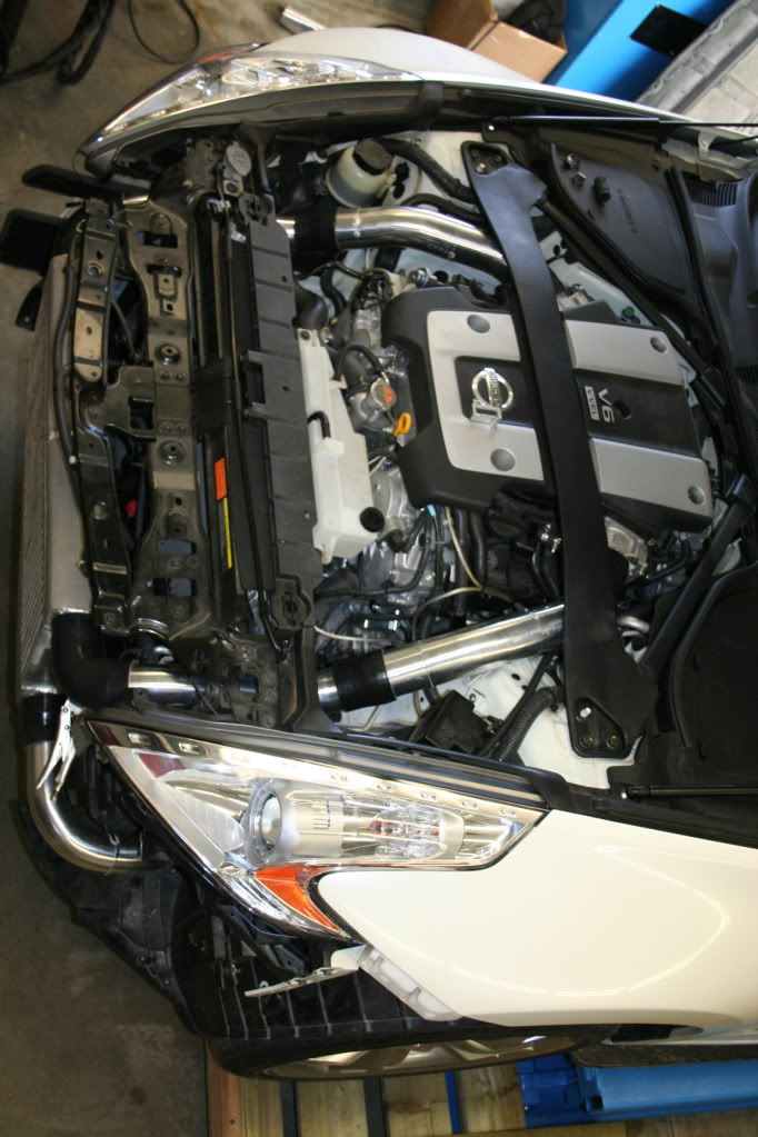
Update day 3:
So I spent a lot of time screwing around with this charge piping going from the turbo to the FMIC, and I can finally say that I am very happy with the way it is turning out.
The section of pipe in front of the driver side wheel stays the same:
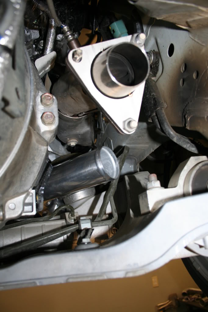
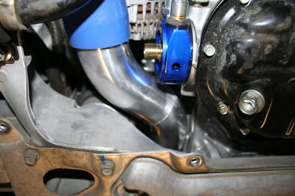
It does change after that, making a turn running behind the radiator:
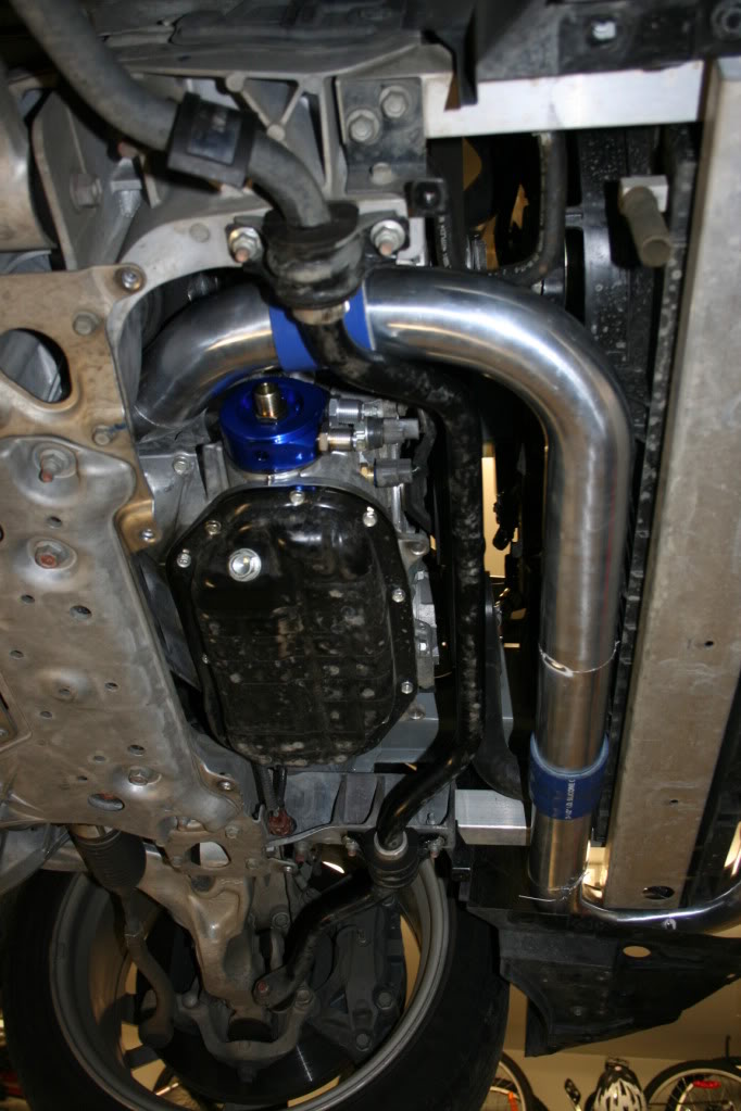
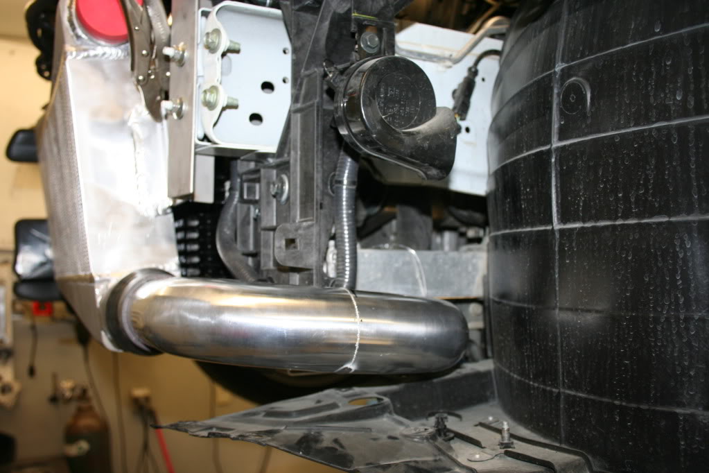
Looping through to the back:
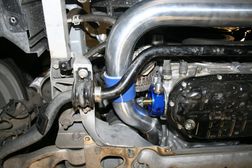
I am very happy with the clearances, but an oil relocation kit will be needed. When the car is down, the clearance increases even more because the sway bar dips down another 1.5�.
I think the hard part is now done. On the back end the exhaust will go smoother because there is much more room to work with. Now I just have to wait for the turbo to arrive. In the mean time I will be ordering an oil relocation kit, and building the charge piping to the TB�s.
So I spent a lot of time screwing around with this charge piping going from the turbo to the FMIC, and I can finally say that I am very happy with the way it is turning out.
The section of pipe in front of the driver side wheel stays the same:
It does change after that, making a turn running behind the radiator:
Looping through to the back:
I am very happy with the clearances, but an oil relocation kit will be needed. When the car is down, the clearance increases even more because the sway bar dips down another 1.5�.
I think the hard part is now done. On the back end the exhaust will go smoother because there is much more room to work with. Now I just have to wait for the turbo to arrive. In the mean time I will be ordering an oil relocation kit, and building the charge piping to the TB�s.
04-08-2012, 05:33 PM
#5
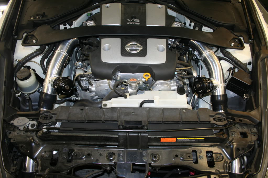
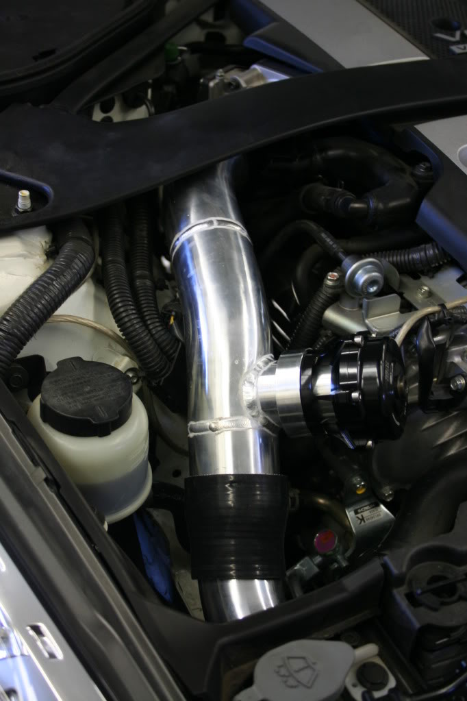
Now for day 4 update:
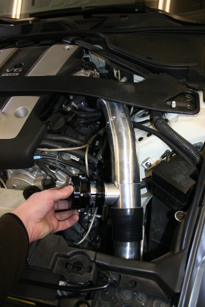
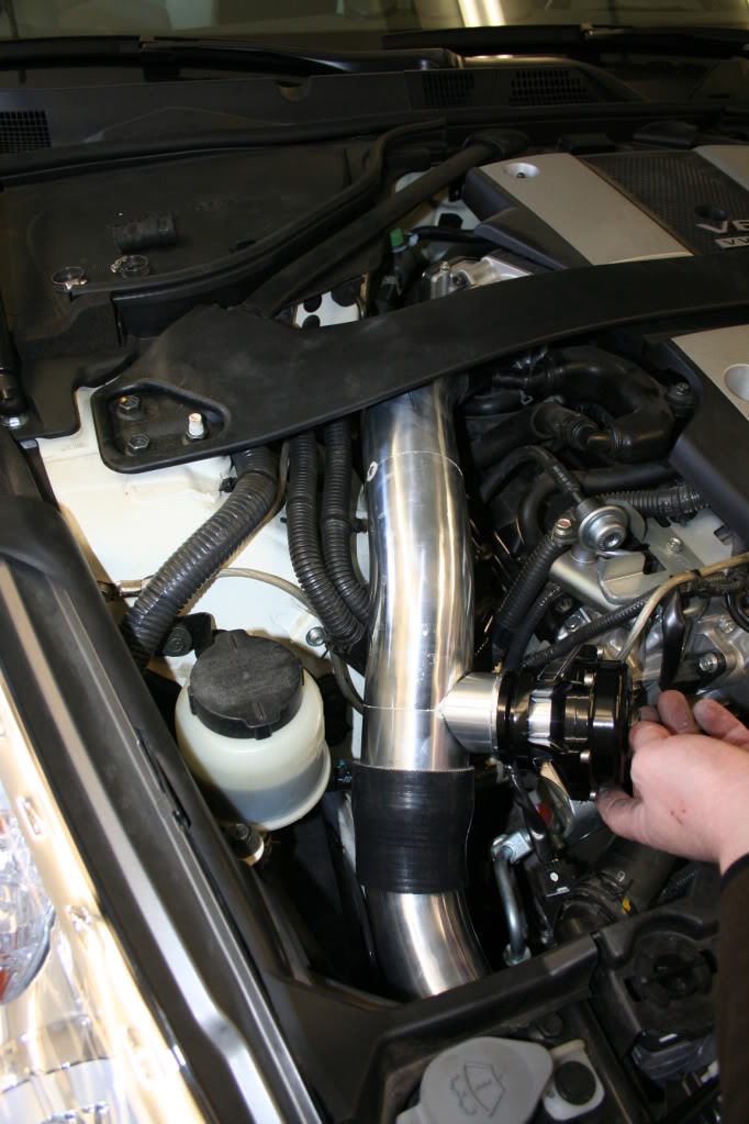
As mentioned earlier, I was working on the charge piping. The key here was symmetry, and it worked out great. The pipes going through the front rad support are 2.5�, and then switch to 2.75� diameter once in the engine bay. The MAF sensors will be as close to the TB as possible (or as far as the plug will reach). This is important because the sensor should be on in far away from any diameter transitions and turbulence, like those that the BOV would cause.
Enough blabber, on to the pictures:
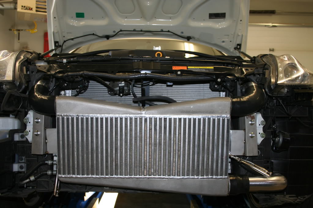
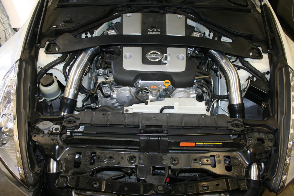
Driver side:
Passenger side:
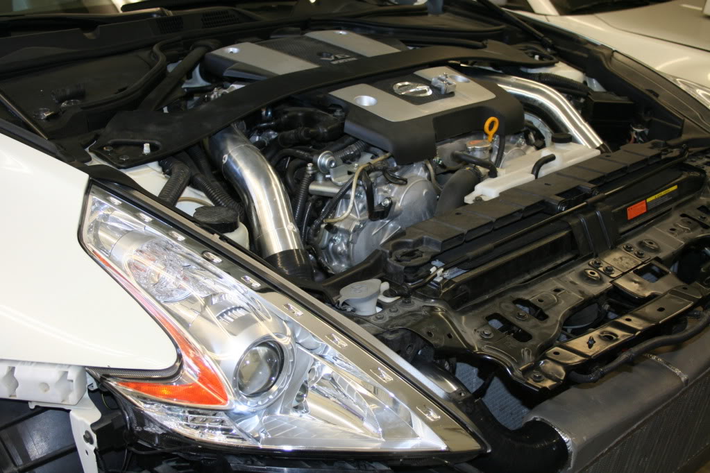
Couple of random shots:
Like I mentioned, the BOV�s will go in tomorrow along with the MAF sensor housings. The turbo will also arrive tomorrow, at which point the stainless fabrication can begin. I am also looking at including an oil pan spacer with an oil drain plug. Not sure who has the best deals on those, so I will have to look around.
As mentioned earlier, I was working on the charge piping. The key here was symmetry, and it worked out great. The pipes going through the front rad support are 2.5�, and then switch to 2.75� diameter once in the engine bay. The MAF sensors will be as close to the TB as possible (or as far as the plug will reach). This is important because the sensor should be on in far away from any diameter transitions and turbulence, like those that the BOV would cause.
Enough blabber, on to the pictures:
Driver side:
Passenger side:
Couple of random shots:
Like I mentioned, the BOV�s will go in tomorrow along with the MAF sensor housings. The turbo will also arrive tomorrow, at which point the stainless fabrication can begin. I am also looking at including an oil pan spacer with an oil drain plug. Not sure who has the best deals on those, so I will have to look around.


Trending Topics

 04-09-2012, 02:03 PM
#10
Day 5 update:
The BOV's and MAF sensor housing are now welded in place:
The turbo also arrived today, and now I am going to start working on the exhaust side of things. I made a quick little bracket to support the turbo in place while the fabrication of the exhaust piping is taking place.
The BOV's and MAF sensor housing are now welded in place:
The turbo also arrived today, and now I am going to start working on the exhaust side of things. I made a quick little bracket to support the turbo in place while the fabrication of the exhaust piping is taking place.


 04-12-2012, 07:38 AM
#16
Registered User

Join Date: Mar 2012
Location: Sonoma County, CA
Posts: 21
Likes: 0
Received 0 Likes
on
0 Posts
First off, thanks for sharing this fascinating journey you're on. It's interesting to see how you work through the process. You said this was to be a user-friendly install, yes? And then I read about welding. I think that''s a bit much for the average gearhead. Too much for me, anyway.
Please continue to keep us up to date on how it's going, and good luck.
Please continue to keep us up to date on how it's going, and good luck.
Last edited by gy954; 04-12-2012 at 07:39 AM.
04-12-2012, 08:10 AM
#17
First off, thanks for sharing this fascinating journey you're on. It's interesting to see how you work through the process. You said this was to be a user-friendly install, yes? And then I read about welding. I think that''s a bit much for the average gearhead. Too much for me, anyway.
Please continue to keep us up to date on how it's going, and good luck.
Please continue to keep us up to date on how it's going, and good luck.
Yes this will be a very user friendly install, nothing to drill/tap modify..ect. If you can install a set of test pipes, you should be able to install this turbo kit. You would also be able to remove this kit in one day and go back to stock. One would never be able to tell the car was ever boosted.
Last edited by Boosted Performance; 04-12-2012 at 08:11 AM.
 04-12-2012, 08:33 PM
#20
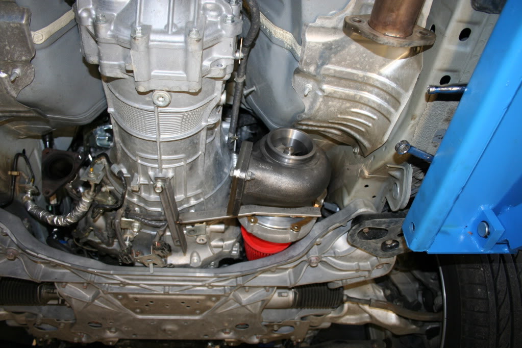
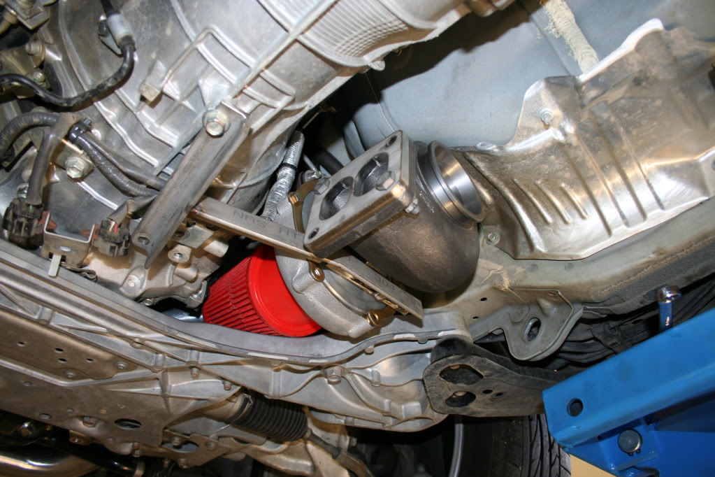
Finally, another update:
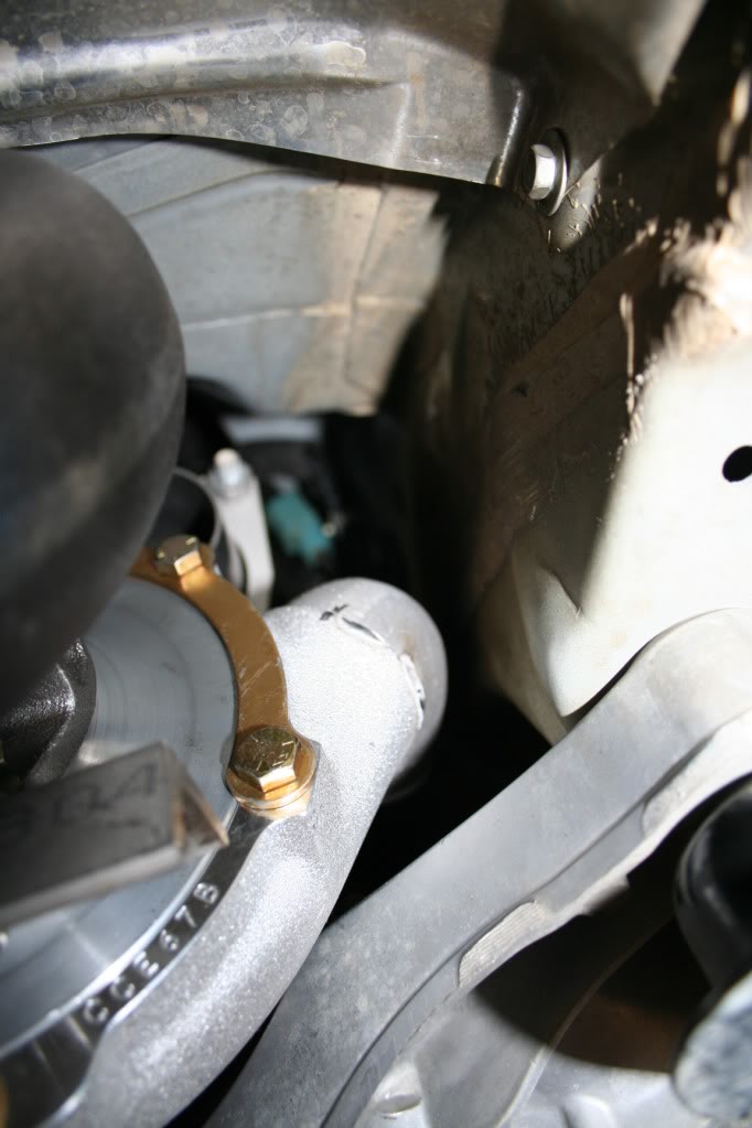
At this point it is safe to say that the hard part is behind me on this build. Today I did the PITA section of piping that feeds one side of the turbine, coming from bank 1:
I also had to modify the Y-pipe from what I have posted a couple of pages back. This is due to the space available between the dual F.I exhaust and the rear transmission support. I could have kept it as it was, and put a 3" 90deg bend right after the transmission. I would have also had to put another 90deg 3" bend. I do not like 90deg bend on the down pipe, especially that close to the turbo. Just a pet peeve I guess, and at the same time improves flow.
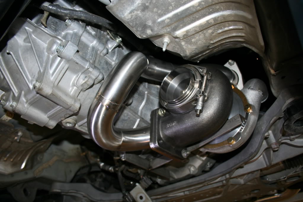
So to avoid that the Y-pipe will look something like this:
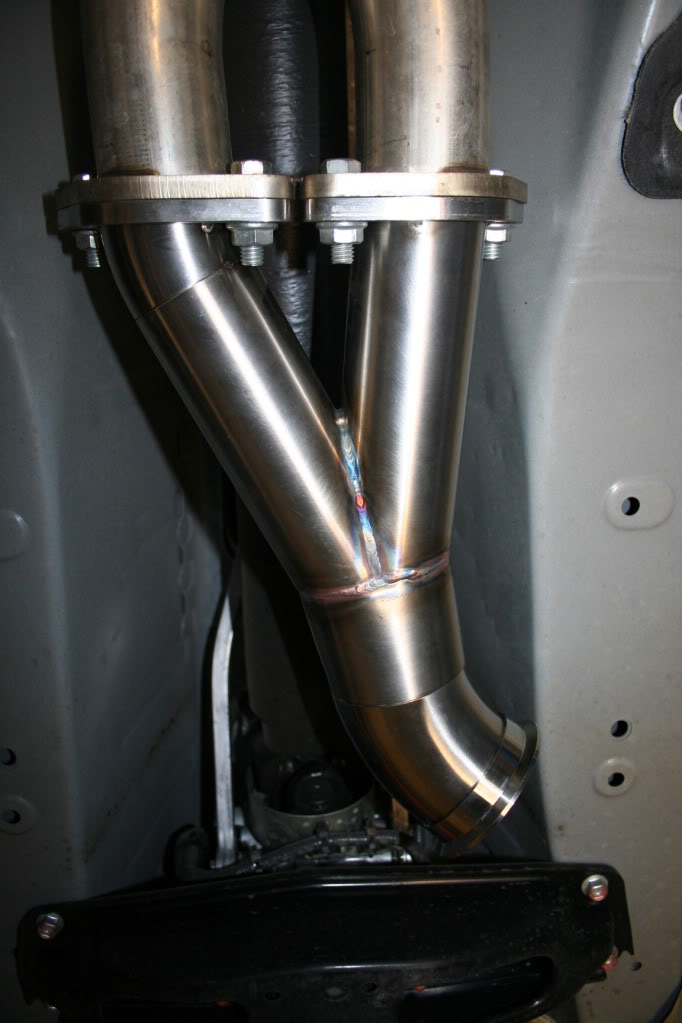
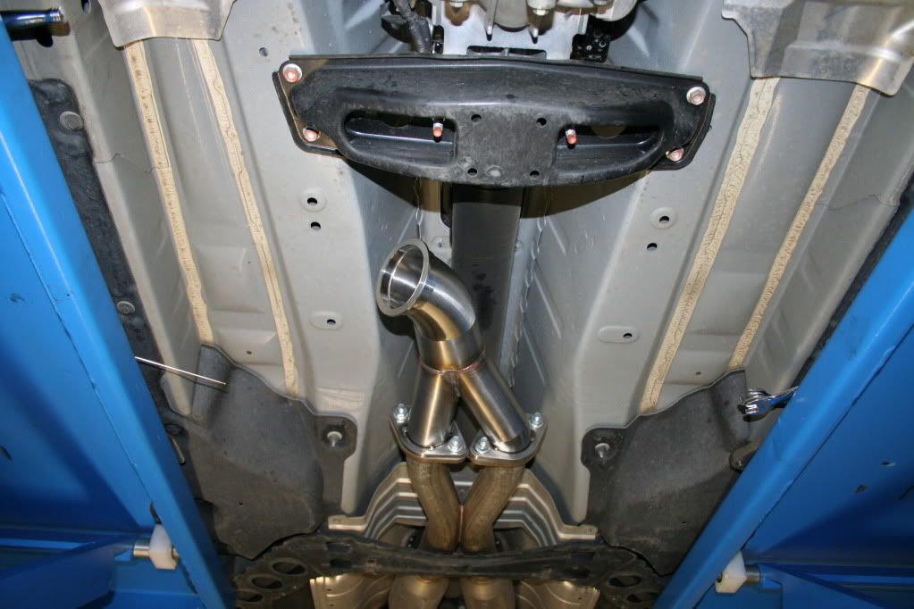
You can see it will be a rather straight 3" shot to the turbine outlet:
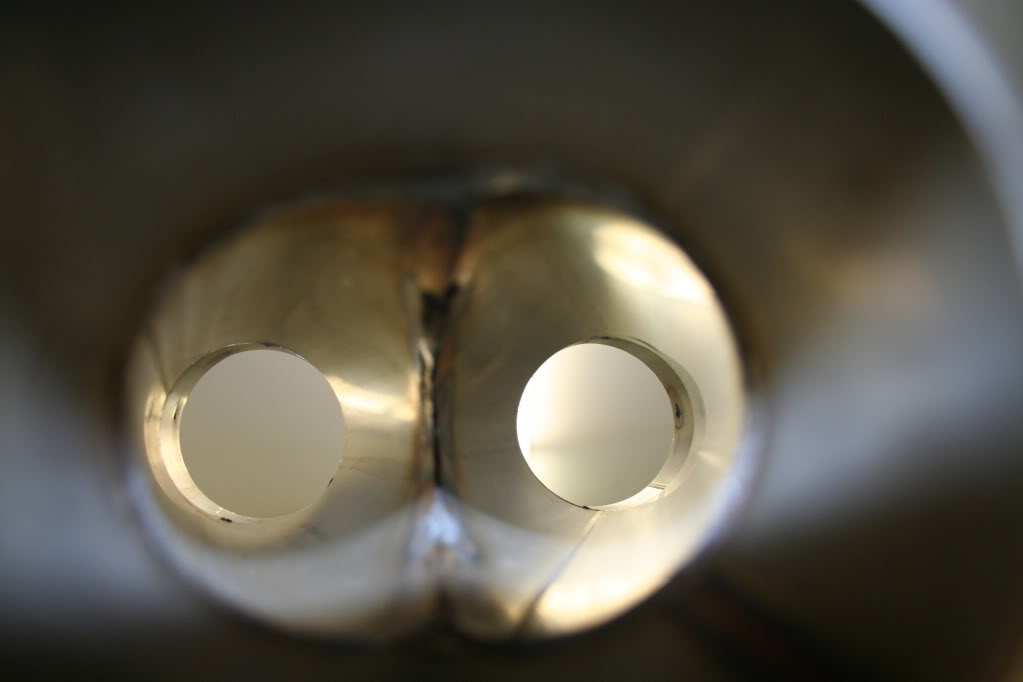
Y-pipe remains nice and smooth on the inside:
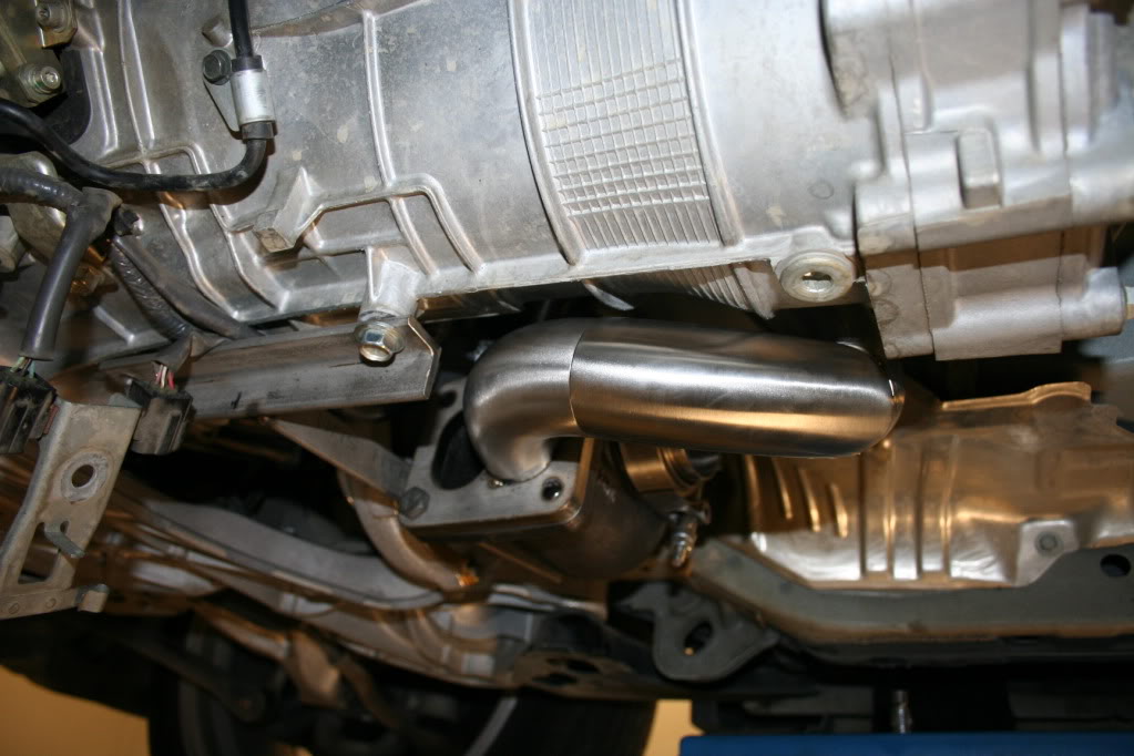
Turbo compressor will have an elbow welded to the outlet:
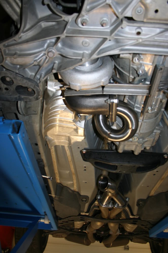
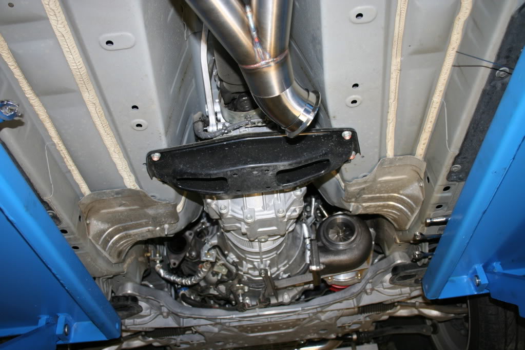
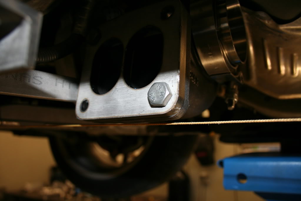
There may be some that think this is hanging low. Well, I pulled a string from the front subframe to the rear skid plate and you can see where the turbo sits in comparison:
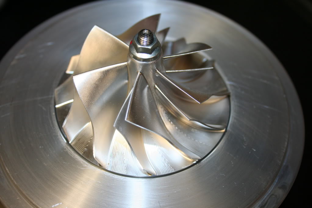
And then, just because it is awesome....the 62mm billet wheel:
By Saturday night I should have the down pipe welded up, bank 2 fabricated to feed the other side of the twin scroll turbine. Once that is done, the manifold will be welded solid and I will move on to the waste gates.
The oil pan spacers should be here late next week, and the oil relocation kit should arrive tomorrow. Other than that, I am set on completing the build on schedule.
At this point it is safe to say that the hard part is behind me on this build. Today I did the PITA section of piping that feeds one side of the turbine, coming from bank 1:
I also had to modify the Y-pipe from what I have posted a couple of pages back. This is due to the space available between the dual F.I exhaust and the rear transmission support. I could have kept it as it was, and put a 3" 90deg bend right after the transmission. I would have also had to put another 90deg 3" bend. I do not like 90deg bend on the down pipe, especially that close to the turbo. Just a pet peeve I guess, and at the same time improves flow.
So to avoid that the Y-pipe will look something like this:
You can see it will be a rather straight 3" shot to the turbine outlet:
Y-pipe remains nice and smooth on the inside:
Turbo compressor will have an elbow welded to the outlet:
There may be some that think this is hanging low. Well, I pulled a string from the front subframe to the rear skid plate and you can see where the turbo sits in comparison:
And then, just because it is awesome....the 62mm billet wheel:
By Saturday night I should have the down pipe welded up, bank 2 fabricated to feed the other side of the twin scroll turbine. Once that is done, the manifold will be welded solid and I will move on to the waste gates.
The oil pan spacers should be here late next week, and the oil relocation kit should arrive tomorrow. Other than that, I am set on completing the build on schedule.