Valve train dilemma could use some suggestions.
 04-03-2017, 07:57 AM
#21

Thats where a lot of misconception comes in, that it doesn't matter before the FI is forcing air into the engine. However thats completely untrue, the power curve is determined 100% the exact same regardless of how the power is made. FI is increasing the volume of air however its not changing the characteristics of how the air is being taken into the engine. Some high winding high power builds myself and others have ran into limits and had to go to bigger cams and custom intakes because the intake side was choked and trying to "shove" more boost into the engine did nothing with that setup yet we where able to by increasing intake side flow while keeping the exhaust side the same.
The reasoning is because outside a roots blower no FI actually forces anything into the engine. twin screen superchargers, centrifugal superchargers, and turbos are all actually true compressors and all compression happens inside the head units. If the engine flows more than they put out some of that air will uncompress and boost will drop however since they arnt actually forcing air they are simply compressing it if the engine cant take any more air in they simply quite making power. It has to do with drive forces, once you exceed the volume the engine can ingest then it pushs back on the headunit compressing air and actually slows it down. This is actually the cause of belt slip on some supercharged applications(at the upper end) and can be super destructive on head units.
The volume a engine takes in is a constant given by its combination of intake, exhaust, heads, and cam. Forced induction changes the density of that air it takes in but doesnt change the volume, its very very easy to run into efficiency issues with the relatively high boost levels imports make(or some of the stuff i work with now which runs just as much boost on engine 2.5-4x as large lol). This is the basis for compound charging as well.
Any limitation a engine has NA will also be a limitation FI because of this, yes more power will be made because more volume but the curve is still going to be limited(eventually power too but no one here trys to go for that.) Thats why as i said, these engines should be easily capable of revving to 8k with 272 cams yet none do
I do find some of the dynos interesting showing 800 hp at 23-26 psi because i know me and binder where about 150ish hp short of that at 22 psi with 6765 and 6766 turbos for ST setups and those are far more efficient turbos but thats a conversation for another time.
Im all about running efficient setups because they make the best average power, mismatching parts isnt efficient which is essentially what everyone does in this community running a intake that cuts off at 7k with cams designed to go to 8k and head port work designed to go to 9k lol. Plus the greater low end grunt will always "feel" more fun to the end user.
You can see in your own setup dash its starting to drop horsepower about 7300 rpms yet with your combo you should easily be able to take it to 8k, maybe a little further because of the headwork.
Just presenting my 2 cents, not here to argue and I do admit that turbo selection plays a big part, but if you map out VE for an engine across the rpm range and plot that on the turbo's compressor map, there will be some points more efficient for the turbo, others less, billet or otherwise. Some turbos do get more efficient with higher boost pressures, but for the typical small twins most kits use, the exhaust side will limit peak power. Increasing engine VE will result in more power where the VE is better at less boost. Yes, you lose some lower end with some cams, but it's not too far right shifted for the mild range most folks use, 260-270 degrees.
The intake side is a limitation for N/A but not nearly as important under boost based on my experience.
OP, those log style manifolds will help increase spool but those in combination with small turbines will limit your peak power. That style is better than the JWT logs I used before though.
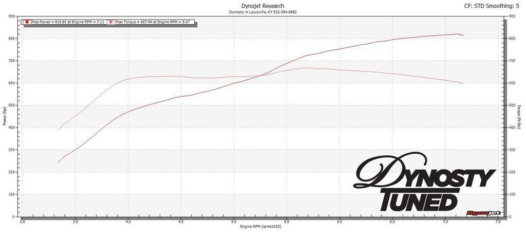
I am injector limited here, but this is a nice fat torque curve for small GTX28s... at only 23psi (rising boost from 18 to 23 actually for this tune to maintain a flat torque curve). I credit the tubular manifolds, Kelford cams, headwork.
The intake side is a limitation for N/A but not nearly as important under boost based on my experience.
OP, those log style manifolds will help increase spool but those in combination with small turbines will limit your peak power. That style is better than the JWT logs I used before though.
I am injector limited here, but this is a nice fat torque curve for small GTX28s... at only 23psi (rising boost from 18 to 23 actually for this tune to maintain a flat torque curve). I credit the tubular manifolds, Kelford cams, headwork.
Last edited by jerryd87; 04-03-2017 at 08:31 AM.
 04-03-2017, 08:06 AM
#22
personally i think the dynos are a little "happy" ill be completely honest with you a billet wheel 20g flows exactly the same as cast at 25 psi. the advantage it has is slightly better spool time. In FI setups the nitrous increases power mostly through intake temp drops, if you run methanol injection(pure meth not the mix although typical disclaimer the pumps arnt made to use for a fuel aand thats technically a fuel yada yada) the nitrous will USUALLY be a power loss at that boost level because it displaces air, nitrous is roughly 1.45:1 density ratio vs normal air and boost at that level post intercooler is typically around 2.2:1. always better to drop the temps with intercooling or fuel rather than n2o.
n2o in a FI setup is best used for bringing a car up on the converter especially a turbo car when staging at the strip.
I made 850 hp at 32 psi on 93 octane, originally ran direct port methanol injection, later cut it out and still used 93(although i ran 8:1 compression). hals car made 770 hp on 116 octane lol(i would say prob comparable to my 850 because his dyno is known to read very very low.)
From reading about cars with similar setups and power numbers they have made with the 18g and 20g turbos. @ 25psi on C16 with billet wheel 20g's and with the 50-75 dry shot I should be able to crack off an 800ish number. Theoretically. Other turbo cars running a 50 dry shot have picked up upwards of 150hp from the N2O alone. On pump 93 I would like to see the car make 650ish around 17-18 psi and C16 and N2O is where I would like to see a big number. I kinda have a wager going with a good friend of mine that the car will blow up before it makes 750+ and I won't be driving the car on the race gas tune very often. We can get into all the small details of making efficient hp but when the pen meets the paper there's only one way to find out how much power I can make with this setup. I totally understand that without the small details and crunching numbers there is no big power. But I'm going to use technology that already is proven for making power. I'm not on a path to develop any new technology. I talked to Logan at Dynosty and unfortunately they are booked until the end of May. Which will give me plenty of time getting all the bugs worked out of the car and figuring out the wiring for the Haltech. I need to wire the secondary fuel pump, nitrous, boost controller, wideband, and fuel psi sensor. Does anyone have a schematic of how they wired their external solenoids and relays?

 04-03-2017, 12:27 PM
#25
It allows a straighter shot into the valves smoothing out the airflow path allowing both higher velocity and more total airflow for a given port volume. The problem is it shortens the runners to a point it gives up low end grunt and right shifter the power band 1000 rpms. IIRC from measurements a custom intake with a straighter airflow path and properly tuned intake runners would make a ton more power and provide a much better powerband i think i needed 2 extra inches of runner. something like this would be better suited to the 272 cams however it still would be a far cry from ideal. The biggest purpose for me was i was trying to right shift my combo on purpose to tune traction because i ran a quick spool setup on my 6766 1.32 ar turbo.
CJM has the right concept as far as overall design goes, the problem is for the price you can get a custom built intake tuned to your exact setup from someone like hogan or wilson who have been doing it for decades rather than a general "off the shelf boxed" approach that isnt really tuned to any specific setup. I know me and CJM have gotten into it in the past and they have tried to claim a sheet metal intake is "weak" but the reality is tens of thousands of sheet metal intakes are out there running anywhere from no boost all the way up to 150+ psi in tractor pulling rigs(which use almost exclusively sheet metal solutions).
People don't realize but airflow into and out of the engine isnt a constant stream be it NA or FI, its harmonic pulses or in simple terms "gulps" like if your chugging a pop or something. Goal is to allow the most efficient pathway for those "gulps" so the engine can get the biggest ones into the combustion chamber as possible.
Last edited by jerryd87; 04-03-2017 at 12:32 PM.
The following users liked this post:
bealljk (04-18-2017)
04-18-2017, 01:47 PM
#26
New Member
Thread Starter

Well I got everything installed and the motor back into the car. Now it won't stay running. I'm getting a right bank cam angle sensor code so I replaced the cam sensors and crank sensor and same problem. It initially fires up then dies. I may have had timing off and bent valves but I'm not sure at this point. I pulled the front cover back off last night and re did the timing. It is 100% for sure on now. Car still wouldn't start today. I installed stage 2 CJM return kit 1000cc injectors and jwt c8 cams and springs. I went over everything 20 times to make sure it was correct and I can't figure it out. I do have low fuel psi its about 25psi. but I can't adjust it until the car will idle. I tried turning the adjustment screw on the regulator with no change. So today I did a compression test. Right bank was 95, 95, 95. Left bank was 115, 115, 115. The car has 8.5-1 CP pistons. Did the test cold obviously without oiling the cylinders. Do u guys think I bent the valves with those compression numbers? Am I possibly having a fuel issue? I'm kinda stumped. The car had 775 cc injectors in it before this and ran great I figured the 1000cc wouldn't be a huge change in idle. I could really use some help.
04-18-2017, 11:15 PM
#27
350Z-holic

iTrader: (13)

People don't realize but airflow into and out of the engine isnt a constant stream be it NA or FI, its harmonic pulses or in simple terms "gulps" like if your chugging a pop or something. Goal is to allow the most efficient pathway for those "gulps" so the engine can get the biggest ones into the combustion chamber as possible.
04-19-2017, 12:17 PM
#28
New Member
Thread Starter
Nevermind I think I figured it out. Valves are fine. I forgot to put an oring in where the factory psi regulator goes with the return correction kit...Oops gonna fix it tonight and fire this ***** up! Hopefully...
04-19-2017, 04:19 PM
#29
New Member
Thread Starter
Well my hopes and dreams are pretty much destroyed. I now have fuel psi. So one issue is corrected. Now the car still isn't right. It will start and run but dies. Still throwing a cam sensor code P0340 for bank 1 sensor fault and VDC and slip lights both come on. I unplugged the crank sensor and was able to keep the car running but it sounds like complete crap and im getting a backfire every so often when it's running. I'm really out of ideas with this one. Everything is plugged in correctly coil packs etc. I did replace the injector harness with the new injectors I installed. I put the connector labeled #3 cylinder on #3 cylinder and the rest lined up right as they should. I labeled the coil pack connectors when I removed them so I couldn't goof that up. I changed plugs last night with the old plugs I knew worked and that didn't solve anything. I'm really confused as to what happened I took my time and did everything as the manual stated. Timing is right checked that the other day. Fuel psi is right fixed that tonight. What else could be making it throw a cam sensor code? JWT says if it throws a P0011 or P0021 the timing is off and I'm not getting that code. Is it possible that when the cams were made that they miss placed the sensor dial I'm starting to wonder about that.
04-19-2017, 04:25 PM
#30
New Member
Thread Starter
I think I'm going to plug the Haltech in and try to do some logs to figure out wtf is going on here cause I'm getting frustrated. I am an experienced technician and this one is kicking my @ss.
04-19-2017, 07:45 PM
#31
New Member
Thread Starter
I figured it out!!! Man that was a b*tch. The bank 1 cam sensor connector wasn't locking on all the way. I had a hell of a time getting it off the first time and must have broken it. But I wedged a pry bar behind it and started the car and it runs much better now. Still won't idle but thats to be expected with bigger cams and lots more fuel. As soon as I find a new connector I'll get this thing on the road for a test drive!

