When you click on links to various merchants on this site and make a purchase, this can result in this site earning a commission. Affiliate programs and affiliations include, but are not limited to, the eBay Partner Network.
Recently a new Nissan specific sub-forum was started on romraider. There is a ton of really good info on there including a method for unbricking or reflashing our ECU's using free and readily available software. So far I don't know of any openly available kernels that will do this through OBD2 which is the only down side. A lot of development still can (and needs to) be done but I just wanted to let people know that there ARE other options out there and tuning this generation of Nissan's without spending a bunch of money IS definitely doable. A car is a car and an ECU is an ECU, yeah there are differences between them but there's nothing stopping Nissan owners from tuning their own cars compared to the opensource tuning done by the Subaru community. The more people that get involved the better the opensource info will get. Check it out!
Edit: Here are step by step instructions on how to do this (with pictures).
Preliminary Note: you have to open up your ECU and solder connections to the printed circuit board in order to utilize this method. It is not difficult as long as you are very careful and have a reasonable amount of experience with a soldering iron. If not, you could very well permanently damage your ECU. Before doing anything, I highly advise you dump a copy of your ROM (and make sure it isn�t corrupt) by utilizing fenugrec�s nisprog software which can give you a copy of your ROM using an OBD2 to USB �dumb� cable. When you connect your ECU to the Renesas FDT Software (Step 4) it automatically erases your ROM.
Step One: Access Hardware
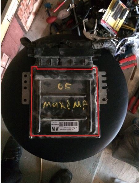
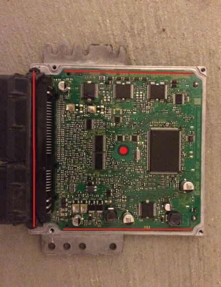
Remove ECU from vehicle, remove ECU�s cover screws and use a utility knife to remove the top cover. Cut through the adhesive sealant (location shown in red below) while at the same time carefully prying open the case with a flathead screwdriver or similar tool, the ECU has sealant all the way around the perimeter of the case. Be very careful not to damage the PCB during this process. Slow and steady wins the race. Some people also apply heat with a heat gun to make it easier to separate the sealant, I have heard mixed reviews on this approach. Remove the lower cover the same way, note that there is adhesive sealant in the center of the PCB that can also be carved out with your utility knife.
Step 2: Solder Connections to PCB
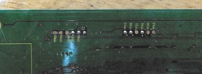
Turn the ECU over and locate these test ports (note: many PCB�s do not have the TP�s labelled but TP use should be the same. To verify you have the right TP�s you can measure voltages, frequency, and check continuity with a multi-meter between the TP and the corresponding MCU pin; the MCU pinout can be found in the MCU�s datasheet. Examples: you can measure 5V between TP84 and TP80 or TP81 (both are ground) or measure continuity between MD1 TP and MCU pin 55. When measuring MCU pins, find the nearest resistor, capacitor, solder joint, TP, etc. to apply your test lead to, do not apply the test lead directly to the MCU pin since you can damage the pin.)
TP82 = 12V+ (Optional Use)
TP83 = 12V+ (Optional Use)
TP80 = Ground
TP81 = Ground
TP84 = 5V+ (Optional Use)
TP(unlabeled) = NA (Do Not Use)
TP42 = PB14 (Do Not Use)
TP35 = SCI1 TX (Serial Communication Interface 1 Transfer)
TP31 = MD1 (One of the MCU Mode Selection Pins)
TP34 = SCI1 RX (Serial Communication Interface 1 Receive)
TP30 = WDT (WatchDog Timer = 250Hz/50% Duty Cycle)
TP43 = nRES (MCU Reset)
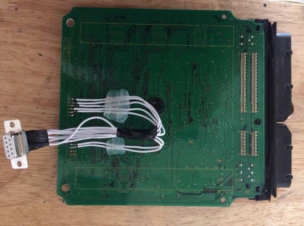
Next solder approximately 28-32 gauge wire (solid wire is much easier and better than stranded wire) to the necessary TP�s as shown below. Use hot glue or similar to provide strain relief! I put the wiring in place and glued them to the PCB before soldering. I also used a solder-type DB9 D-SUB connector to make plugging in and unplugging my SHBootmode tool easier and quicker (more on this later).
Step 3: Build SHBootmode Circuit
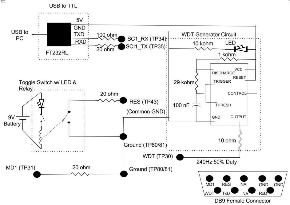
Next we have to make a circuit which will put the ECU�s Renesas Super-H MCU in Bootmode, keep the WDT satisfied and allow serial communication between the MCU and your computer. This is much easier than it sounds. Here�s an overall schematic of the circuit I ended up building:
Note that the �Toggle Switch w/ LED & Relay� is not necessary but was a personal preference. A simple SPST switch would suffice. This circuit has worked for me many times and is not difficult to build. Since I used a DB9 Female Connector for the ECU connection, the DB9 male connector will be mirrored from the above diagram.
First: solder a 20 ohm resistor from MD1 to Ground on the male connector. (note: this is the part of the circuit that actually enables bootmode on these ECU�s. Much more information can be in Section 4 � Operating Modes of the Renesas SH7058 Hardware Manual.)
Second: solder a 20 ohm resistor to a switch and use it to connect nRES to GND.
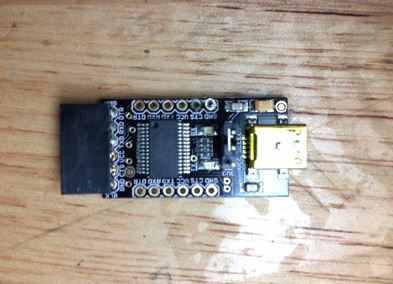
USB to TTL Interface (FT232RL Breakout Board):
On the breakout board, solder wires to 5V power, GND, SCI TX, and SCI RX (note that SCI TX and SCI RX will be opposite the MCU connector, i.e. breakout board TXD goes to ECU SCI1_RX and breakout board RXD goes to ECU SCI1_TX). I used a 100 ohm resistor between TXD/SCI1_RX and a 20 ohm resistor between RXD/SCI_TX which has worked well for me and provides some circuit protection for your ECU. (note: Shuher noted that the TX and RX should be the same and that he used 20 ohm resistors for both.)
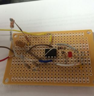
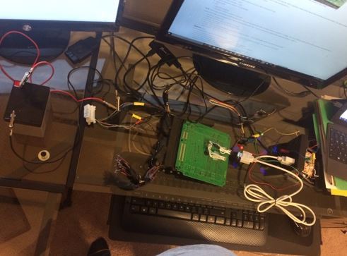
Third: build the WDT generator circuit, the goal here is to achieve a 250Hz/50% Duty Cycle signal but the supervisor chip allows some leniency in frequency and duty cycle so don�t waste time trying to get it absolutely perfect. I used a 555 timer and produced a 240Hz/50% Duty Cycle signal which always seems to work. Make sure to look up the correct pinout for your 555 timer as they are not all the same. I powered mine via the FTDI breakout board�s 5V power output and ground (make sure you ground the WDT generator the to the DB9 connector GND to ensure a common ground). Depending on what resistors you have (or don�t have) lying around you can add them in series or parallel to get the right ohm reading. Here is what my circuit ended up looking like:
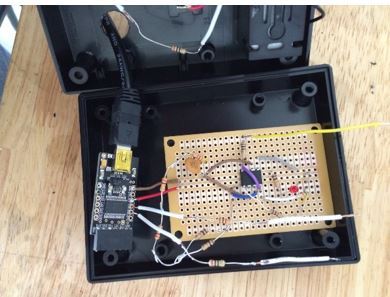
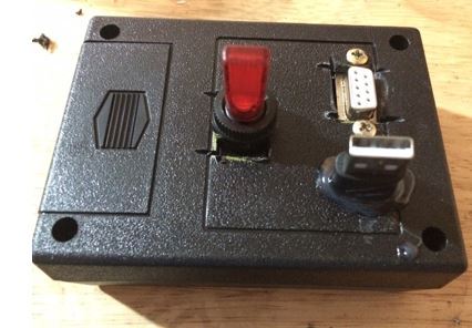
Here is what my SHBootmode tool looks like with all components assembled and put in a case:
Step 4: Software and Reflash
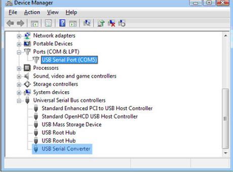
Connect your SHBootmode tool to your PC via USB port and ensure the FTDI driver loads. If it doesn�t you can do this manually through Device Manager on Windows. After the driver installs, go to Device Manager, click on Port (COM & LPT) and see which communication port was assigned to your FTDI device (example: COM1).
Connect your SHBootmode tool to your ECU (after doing this enough times you�ll understand why I used a connector). First close your RES switch, then power up your ECU with an appropriate 12V source. Make sure to apply 12V to the ignition pin as well. After your ECU has power, open your RES switch and your MCU should now be in Bootmode. More information and a detailed sequence of operations can be found here: https://nissanecu.miraheze.org/wiki/..._of_operations. (Also, there is A LOT of really good information on this wiki as well thanks to fenugrec and Shuher. I know fenugrec has spent countless hours for the past few years to come up with the information on this wiki so please give it the respect it deserves!)
Download the Renesas Flash Development Toolkit (Free Software on Renesas Website) and start the Basic version of the application. (Note: when using the Renesas FDT software, as soon as it establishes a connection with your ECU it automatically erases your ROM!!! This is why it is so important to create a backup of your stock ROM before starting the reflash process.) Select Generic BOOT Device, Select the COM port you found in the previous step, After pressing next your MCU�s type should be displayed, Enter 10 MHz Crystal (this is a very common crystal oscillator frequency on these ECU�s but may differ between ECU�s), Select BOOT Mode Connection, Enter your preferences then click finish.
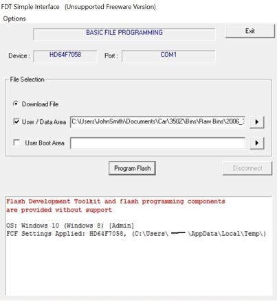
You should end up at a screen that looks like this:
Select User/Data Area and select the ROM file location that you want to reflash to your ECU (SH7055 MCU is 512kb, SH7058 MCU is 1024kb), deselect User Boot Area, and hit Program Flash. If all goes well it will reflash your ECU in about 5 minutes (for a 1MB file) and you should see something like this:
OS: Windows 10 ( Windows 8 ) [Admin]
FCF Settings Applied: HD64F7058, (C:\Users\JohnSmith\AppData\Local\Temp\)
FDT API initialised: version 4, 09, 02, 000
Clock Frequency (External) = 10.0000MHz, Clock Mode = 0, CKM = 4, and CKP = 2
Connecting to device 'HD64F7058' on 'COM1'
Configuration:
'BOOT Mode' connection - using emulated interface
Opening port 'COM1' ...
Loading Comms DLL
Loaded Comms DLL
Initiating BOOT SCI sequence
Attempting 9600
Received immediate response from device: 0xE6
Detected generic boot device
Sending inquiry for getting line size
Buffer size has been set to default (128 bytes)
Sending selection of device command
Selection of Device - Device selected, code 0601
Sending selection of clock mode
Sending selection of clock mode
Selection of Clock Mode - Clock selected, code 0
Changing baud rate to 38400 bps
Set baud rate value = 38400
Determining block usage
Connection complete
Processing file :"C:\Users\JohnSmith\Documents\Car\350Z\Bins\Raw Bins\2006_350Z_1CF43D_1.bin"
Loading image file : 'C:\Users\JohnSmith\Documents\Car\350Z\Bins\Raw Bins\2006_350Z_1CF43D_1.bin'
Loading image file : 'C:\Users\JohnSmith\Documents\Car\350Z\Bins\Raw Bins\2006_350Z_1CF43D_1.bin'
Operation on User Flash 0
Loaded the Write operation module
Writing image to device... [0x00000000 - 0x00001C7F]
Writing image to device... [0x00002000 - 0x0000447F]
Writing image to device... [0x00004480 - 0x000044FF]
Writing image to device... [0x00004500 - 0x0000457F]
Writing image to device... [0x00004580 - 0x00004A7F]
Writing image to device... [0x00004A80 - 0x00004B7F]
Writing image to device... [0x00004C00 - 0x0000617F]
Writing image to device... [0x00006180 - 0x0000627F]
Writing image to device... [0x00006300 - 0x0000B17F]
Writing image to device... [0x0000B180 - 0x0000C27F]
Writing image to device... [0x0000C280 - 0x0000CAFF]
Writing image to device... [0x0000CB00 - 0x0007FFFF]
Data programmed at the following positions:
0x00000000 - 0x00001C7F Length : 0x00001C80
0x00002000 - 0x0000447F Length : 0x00002480
0x00004480 - 0x000044FF Length : 0x00000080
0x00004500 - 0x0000457F Length : 0x00000080
0x00004580 - 0x00004A7F Length : 0x00000500
0x00004A80 - 0x00004B7F Length : 0x00000100
0x00004C00 - 0x0000617F Length : 0x00001580
0x00006180 - 0x0000627F Length : 0x00000100
0x00006300 - 0x0000B17F Length : 0x00004E80
0x0000B180 - 0x0000C27F Length : 0x00001100
0x0000C280 - 0x0000CAFF Length : 0x00000880
0x0000CB00 - 0x0007FFFF Length : 0x00073500
510.88 K programmed in 149 seconds
Operation on User Flash 1
Loaded the Write operation module
Writing image to device... [0x00080000 - 0x000A79FF]
Writing image to device... [0x000FFF80 - 0x000FFFFF]
Data programmed at the following positions:
0x00080000 - 0x000A79FF Length : 0x00027A00
0x000FFF80 - 0x000FFFFF Length : 0x00000080
158.63 K programmed in 46 seconds
Image written to device
Troubleshooting
As you can imagine I ran into all kinds of issues throughout the process, here are a few I can remember off the top of my head:
-Double and triple check your wiring and hardware connections!
-Systematically go through everything with your multi-meter to ensure everything is connected well and correctly.
-Make sure everything has a common ground connection (ECU-USB to TTL-WDT Circuit-PC via USB)
-Measure your WDT signal (buying even a cheap log analyzer can really help here)
-Make sure nothing is connected to the obd2 k-line, this is directly related to the MCU�s serial(1) TX/RX pins.
-Download the hardware manual/MCU datasheet to help with miscellaneous issues and to get a better understanding of how all this works.
-Download a serial terminal such as Realterm to test communication between PC and MCU
-Check driver settings in Device Manager, lowering the latency timer can help with echo and communication errors.
-Do a lot of reading!
I�m definitely forgetting some but this is a good place to start when running into issues.
Last edited by AK Eyes; 06-05-2016 at 09:41 AM.
Reason: Not many responses, want to gain more interest in topic.
Vague on purpose since there is A LOT of detailed info on romraider that I wouldn't be able to reiterate on here.
Things to take into consideration:
- Maps are not at the same ROM Address for different ECUIDs, most likely you will have to find maps yourself, the needed ones for tuning are a little more obvious which helps. There are a ton of maps and axis in our ROMs, many have unknown uses.
- there is a free ROM dumping tool available for our cars that uses standard OBD2 protocols which means it takes a few hours to download the ROM off your car. The tool is an offset of freediag called nisprog. There is a list of stock ROMs people have dumped on the romraider Nissan forum. If you dump your own ROM please add it to the list so we can find out as much info as possible on our ECUs (example: where different maps are located on different ROMs, where DTCs are stored, etc.)
- pay attention to fenugrecs posts since he has done a ton of development on this, he also has links to more in depth and detailed info.
Feel free to ask me any questions, this is something I've been working on and learning for the past 6 months or so.
Hey murphys_law, glad to see this getting a little attention I started looking for maps awhile back and found a bunch of them but have no idea what they do. I also need to go through and vet out the ones I know are maps from the ones I suspect are maps, and find associated RAM addresses to get an idea of what they do.
Maybe we can play off of each other to find/figure out maps. It sounds like the 06 G35 RevUp ROM is really similar to mine (06' Z RevUp ROM-CF43D)
I haven't been spending as much time with maps lately because I have been trying to write code for the SH MCU using Renesas HEW. Its going slowly but surely, I am pretty aweful at programming in C so that doesn't help...
here is what fenugrec posted on the nicoclub.com forum
"Hi people,
I'm a total stranger here but I've been hacking on Nissan ECUs for over two years now. I've been figuring out the reflashing process for ~2002 onwards ECUs, specifically those with the K-line OBD2 interface since that's what I have on my 04 Sentra.
It's been done before by a few people and companies, but I figured it would be nice to have it documented and open-source. Here's some of what I've been up to : (arg, I can't post URLs due to me being in the "new poster baby sandbox") !!!
nissanecu.miraheze.org NissanECU wiki: lots of reverse-engineering info
"Nissan QR25DE ECU dumping tool " : (***) drawn out thread on RomRaider forums where I posted updates as I made slow progress during 2 years.
So now it's pretty much solved :
- use any software (RomRaider/winOLS/ even a hex editor really) to modify your ROM;
- use (***) freediag / nisprog (software I've been working on in parallel, some custom commands in there, and that's almost it.
The last missing piece was a "reflashing kernel" - the way this works is that the stock firmware doesn't hold the low-level routines for reflashing, so it needs to load a kernel to RAM, and execute it from there. The issue was then finding / writing a kernel...
Hopefully this doesn't count as advertising -- I'm not selling anything, but I'd like to promote a crowdfunding campaign I've set up to fund the final development of the reflashing kernel and associated tools. The result is a fully open-source kernel, which as far as I know is something very unusual on the tuning scene.
The campaign is set to begin very soon. Stay tuned on the crowdsupply website (***) ,project name is "nisprog reflashing kernel" !"
Update: Looks like there has been a proof of concept video posted and some features added to fenugrecs kernel. See the crowd funding link above (I'm subscribed so I can get updates). Release date coming up!
This is a side of tuning that I'd never considered before and it appears that it could open up a whole host of possibilities. A big Thank you to AK Eyes and murphys_Law for opening my eyes, and for the hard work. Looks like I've got a fair bit of reading to do.
Being a software engineer... I'm not surprised to see an open source solution. Back in college, I was making a piggy back tuner for my old DSM. Props for the EE person that did the schematic.
Glad to see some interest. Subaru and Mitsubishi guys have been doing this for a long time and have figured out just about everything in their ECU's. I'm confident we will catch up.
A couple updates:
Now the kernel can reflash the whole ROM sequentially without stopping rather than block by block. It can also compare your stock ROM to your modified ROM and only reflash the block that has changed. Long story short, it can reflash ECU's really fast (if only modifying maps in one block it would take seconds, not minutes. A full rom reflash takes about 3 - 4 minutes.) Feel free to PM me if you have any questions on how to use the software.
Thanks to murphys_laws and others, we have already identified a lot of the maps and other useful values/structures in our ROM's. I think I have just about everything defined in my ROM to do an FI tune. One thing we are currently working on is finding the throttle close rev limiter (we already have the fuel cut part).
NissanTracker - which schematic are you referring to? If you mean the one I made for the SHBootmode/Unbrick your ECU write up than thanks but I'm an ME and made it in paint... haha
So yeah, I thought I'd make an appearance here too - I've been active mostly on the RomRaider forums.
Head over to the RR nisprog thread for the latest nisprog build; github for precompiled kernel builds and/or source code.
Since this isn't getting much attention I thought I would go ahead and post up some eye candy.
This is a screen shot from rom raider of a rom file from a 2006 350Z base 6 speed.
As you can see there are many editable values:
Intake cam timing
Exhaust Cam timing
Rev limit(fuel cut)
Injection Multiplier(aka "K" Value)
Ignition Timing, including where the knock sensors are more sensitive(you can see in the maps the values in red which are +128 of the rest of the map.) By removing 128 you can lower knock sensor sensitivity, which isn't provided for end users on "other" software.
Fuel compensation
Fuel Targets
This is just a start, but I can say that with rom raider, along with the definition files, and fenugrecs reflash kernel thats linked, you can tune most combos. This is something that costs as little as $10 for the vag-kkl cable, with nothing else required.
There is no logging at this point, and I use a software known as "Nissan Data Scan II" to log and do troubleshooting on the Nissans that I mess around with. Its low cost at ~$60.
The definition files that I have started to work on are at the link below, there are a only a few ecus listed as there haven't been a ton of z/g cars that have dumped their roms.
If you are interested in tuning with this the best way to get started would be to buy the kkl/vag com cable and dump your rom so that a definition file can be made.
Just wanted to update this thread with some new information:
I've been working on a new GUI ROM Editor/Viewer that will incorporate fenugrec's flash kernel directly. I talked with AK_Eyes a while back about it, but due to a loss of a job it kind of got put on hold. But over the last month or so I've been working on completing it, and I only have a few more things to work on before it is completed. See the photo for a view of the current progress.
So here's what I have left:
1) Combine the fenugrec's kernel with the C#/WinForms ROM viewer/editor I made. I'm attempting to use InteropServices to do this, but I've been having some trouble due to lack of experience. I'm personally debating whether to just write a class that runs the kernel in the background instead of trying to use Interop to access the C methods. If anyone can contact fenugrec and ask him to help me with this that would speed things along tremendously, or if no one else has experience with this i'll just figure it out for myself.
2) Create a better GUI. I mean just look at the photo lol nobody will want to use the software with the tables looking like that. I'm terrible at programming GUI stuff though. I was thinking about incorporating some heat mapping into the tables to make it look better (similar to pretty much every tuning software out there), but idk.
3) Currently I've been testing the software by simplifying things in the sense of hard coding table addresses for a specific 350Z ROM. I've already written an XML parser for definitions, I just need to switch the hard code with xml parsing code I already have. Shouldn't take too long.
4) Right now if you edit a table, there is a save button which allows you to save the edited ROM. However if you close out of the table edit view, the ROM isn't saved. I need to code something that allows you to make temporary edits and save all of those edits at one time. Saving the ROM every time you edit the table is extremely inefficient and I want to change that.
5) Finally definitions. I've only defined a select few tables for a couple ROMs to test the software. I don't plan on doing this all myself, I'm sure other people can step in and write more definitions with more tables, but that's where it currently stands. I'm also working on a disassembly tool strictly for our ECU's that makes a best guess at where common tables are for undefined ROMs.
I updated the Github repo a little earlier, but I migrated over to a new project so the current public repo doesn't contain all the code. I'll create a new repo soon and post the new link.
 05-24-2016, 07:32 PM


 I started looking for maps awhile back and found a bunch of them but have no idea what they do. I also need to go through and vet out the ones I know are maps from the ones I suspect are maps, and find associated RAM addresses to get an idea of what they do.