Make a line/aux in for your 2003 Bose headunit – step by step guide


 02-19-2007, 10:11 AM
#83
Registered User
iTrader: (3)
Join Date: Nov 2002
Location: CT
Posts: 990
Likes: 0
Received 0 Likes
on
0 Posts
Originally Posted by Jackdaw
I've just done it myself.
It works very well.
Thanks for the initiative and the detailed instructions.
It works very well.
Thanks for the initiative and the detailed instructions.
IF or when you have to spring for a HU not covered under warranty, also remember the 2-ohm speakers are not the same as aftermarket, so you cannot just easily plug in an aftermarket HU to the "Premium" Bose Stock speakers w/o regard for the fact they are different. For example, the rear deck 6x9's have a subwoofer component, just jacking in speakers even with the right impedence means Bass-only:
"The factory subwoofers in this location receive only bass frequencies from the amplifier. If replaced with aftermarket speakers, the aftermarket speakers will only reproduce bass."
Check Crutchfield's Install Caveats on this!
Don't expect the dealer to replace it (I am on #2, first one lasted less than 2 years) after this surgery. Add to that they are known to fail, and this is a good idea how?
Sure, you have a place to jack in your iPod - unless the HU pukes, then you have a lot of nothing. Unless of course you go aftermarket where 90% of the HU's have this function now.
I use a Phillips tape adapter (may as well use the cassette for something) and it's fine with me, well worth not ripping into the dash and invalidating my warranty for the 6-CD, AM/FM, XM radio functions just to gain a "clean" (?) iPod jack.
Personally having dropped some significant change on the car, I'd spring for a few hundred bucks to have one put in professionally using an AUX plug made for the car, which also gives you options to control and charge the iPod through the existing controls.
Just IMHO...to each his own, but think long term if you plan to hold onto the car. Not sure what the Z has now for warranty, but Infiniti will cover this out as a defect to something like 7/70 (have to check, but it's more than the 36 month).
 03-08-2007, 02:21 AM
#85
Registered User

Join Date: Mar 2007
Location: Germany
Posts: 1
Likes: 0
Received 0 Likes
on
0 Posts
Hi @all,
thanks for this howto, it could rearly fit my problem. But unfortunately I dont see any pics of this howto. So if you can help and send me this howto including pics it would be fantastic.
Thx, cton.
thanks for this howto, it could rearly fit my problem. But unfortunately I dont see any pics of this howto. So if you can help and send me this howto including pics it would be fantastic.
Thx, cton.
 04-21-2007, 01:16 PM
#87

Originally Posted by cton
Hi @all,
thanks for this howto, it could rearly fit my problem. But unfortunately I dont see any pics of this howto. So if you can help and send me this howto including pics it would be fantastic.
Thx, cton.
thanks for this howto, it could rearly fit my problem. But unfortunately I dont see any pics of this howto. So if you can help and send me this howto including pics it would be fantastic.
Thx, cton.
+1
Waiting to pull the trigger on my install 'till I get a better idea on how to do this (pics!)
04-30-2007, 02:57 PM
#90
Registered User
iTrader: (1)

Join Date: Mar 2007
Location: Indy
Posts: 18
Likes: 0
Received 0 Likes
on
0 Posts
This mod is a must!! just did it in 20 minutes (i've soldered before). Also don't use a tape!! All you need to do is look for the little black switch in the back there is a spring near it, remove the spring and the little lever, and you got it! No cassette needed.
 05-22-2007, 08:16 PM
#92
Registered User
iTrader: (3)
Join Date: Nov 2002
Location: CT
Posts: 990
Likes: 0
Received 0 Likes
on
0 Posts
I still say yank the HU, get the adapter to allow use of aftermarket with existing speakers until they begin to fail, buy a new HU, amp, and iPod controller. I just put a new JVC in my '91 B13, the iPod adapter unit and cable was a snap install - just plugged into the back of the deck, and full controls. It's a night and day comparison having a HU designed to work with an iPod, with an optional iPod controller buried in the dash.
Why? Well, because -
- it charges and plays my iPod, controlled completely through the HU with a click-wheel style control, 80 GB of music, audiobooks, video, etc. Even the new G35 Sedan has a big-whooo 10GB storage unit - can you say "Original iPod v1.0 had that"?
- I can navigate the menus from the controls similar to the iPod controls, reads the Menu choices, Navigation is similar to the clickwheel
- plays MP3's on disc, DVD MP3's and DVD Video, WMA's when not using the iPod - what good is a 6-disc changer if it only can play conventional CD's?
- Satellite tuner included, not an add-on, only an antenna (got that) and account activation required.
- it has actual equalizer settings and DTS filters, presets, etc.
- add a screen and I have DVD video, too
Cost: ~$350 for a new HU and the iPod adapter, w/o speakers or amp (already had a few of each). Even with the conversion in this thread you still have really poor control of the iPod (try that one while driving), you cannot read the playlists, etc. This is NOT high end equipment here, just decent equipment.
Why would I want to screw with a BOSE HU that frankly I'd just put out onto a forum for sale for the poor bastards whose BOSE units fail out of warranty and the dealer tells him "hand over the $$$...or nada". People make really nice double DIN dash replacements for the '04 style G Coupe. Looks like OEM finish, never know it wasn't.
It's just a matter of time before I yank that BOSE unit, not being able play MP3 discs or DVD's with GB's of tune, or being able to conveniently carry around an 80GB iPod worth of music and just plug it in with full controls and display makes the BOSE a Dino. When I drive my other cars that can do these things, it just makes the BOSE seem like a relic. A CASSETTE?
No offense, just a reality check - nice to putter sometimes, but this conversion is a complete waste of time - lipstick on a pig, and the only thing worse than that is having to buy the pig again later when the HU eventually fails (again). There's no excuse for a "premium" sound system to blow a side after less than 2 years, only worse thing than that is having it blow out of warranty...lower pricing + better technology has left this system off the back, badly.
05-29-2007, 09:34 AM
#93
Registered User
iTrader: (8)

Join Date: Apr 2007
Location: Fawn Liebowitz's Hometown!
Posts: 173
Likes: 0
Received 0 Likes
on
0 Posts
tricked04,
If I drive down to Indy, wanna help out a fellow Z owner!? I'll buy beers!
If I drive down to Indy, wanna help out a fellow Z owner!?
I'll buy beers!
Originally Posted by tricked04
This mod is a must!! just did it in 20 minutes (i've soldered before). Also don't use a tape!! All you need to do is look for the little black switch in the back there is a spring near it, remove the spring and the little lever, and you got it! No cassette needed.

 06-13-2007, 11:41 PM
#96
Registered User
Thread Starter

Join Date: Sep 2004
Location: Singapore
Posts: 38
Likes: 0
Received 0 Likes
on
0 Posts
@ SteveZ
Kinda hostile?
I actually did this because I live in a country where
- Any Z parts have to be shipped in especially (I couldn't bear to ship USD35 worth of double din adapter from the US and thats assuming I could make it around the increasing reluctance of US dealers to ship overseas)
- There aren't many 350Zs around and the chances of getting a shop familiar with the insides is limited.
Plus
- I like the ergonomics of the stock headunit
- I'm not using an ipod, what I have is permanently powered and designed for in car use so control or charging is not an issue
- I've never obsessed over warranties (in Asia they're not what you would expect in the US)
- Doing it myself made the car seem more "mine"
That said today I would probably get over the "international shipping of 35 dollar part problem" and use one of the new USB ipod decks.
@everyone else
I'm really sorry about the pictures. The site where I hosted them has long since deleted them and the originals were lost over Christmas when a lightning strike took out my media server's Raid5 (strangely the non-redundant system drive carried on working happily. Moral: ALWAYs backup to offline storage).
My apologies I hope the thread is still useable without them. FWIW my Z and this mod are still going strong. So is the omnifi which is now on its 3rd HDD (it gets hot here in Singapore).
Remember only the first head units need this mod. More recent ones you can just buy a part and plug it in.
Cheers
Eric
08-17-2007, 12:58 AM
#97
Registered User

Join Date: Jun 2005
Location: London, England
Posts: 68
Likes: 0
Received 0 Likes
on
0 Posts
Originally Posted by something fishy
Remember only the first head units need this mod. More recent ones you can just buy a part and plug it in.
Cheers
Eric
Cheers
Eric
08-26-2007, 02:57 PM
#98
Registered User
Join Date: Jun 2005
Location: London, England
Posts: 68
Likes: 0
Received 0 Likes
on
0 Posts
Pics and instructions posted in full, pics hosted by Photobucket.
Copied from the first page, this is a combined message containing all of the instructions in one easy posting so that it can be copied and printed.
****************************************************
1. Remove the dash and take the head unit out of it.
The guide here: http://liljerk.morpheus.net/350Z/ is excellent (thanks my350z.com).
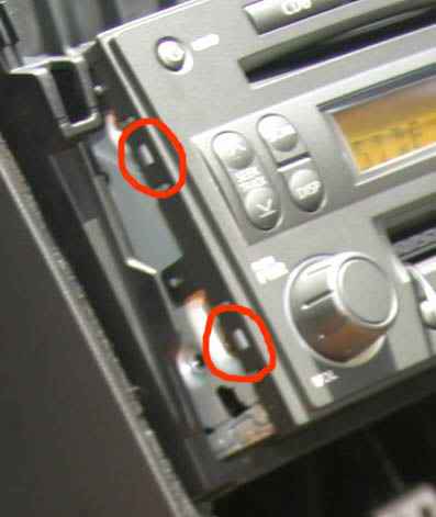
2. Remove the front (plastic) panel of the head unit.
It is held on by little clips all around perimeter. You can see two of them in this shot which was taken when I was testing to see if it worked. There are two on each side and three at the top and bottom. Slide a small screwdriver in between the plastic and the metal, gently lever the plastic up from the clip and slide a thin piece of card between the two to allow you to tackle the next one.
All clips done the front panel and the PCB that holds all the front panel controls should come off without much force (if you have to force it, some of the clips aren’t loose)
3. Remove the (perforated) bottom of the head unit.
It is held on by four small Philips screws through the bottom panel, two screws through the back and two screws through the front. All these removed carefully lever the bottom panel off at each side (at the join line) it will take a little force as there are some friction clips built into the side and (I think) the front.
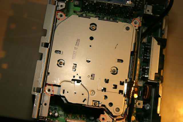
4. Remove the cassette unit.
The cassette unit is now sitting right in front of you. This picture was taken while I was reassembling the head unit but shows where the four screws that hold the cassette unit in are (they’re removed in this picture). To take the cassette unit out just remove these four screws and lift the unit vertically upwards.
5. Find the correct PCB traces and break them.
If you cassette unit looks like mine the back will look like this. The part sticking up (with 97-794-Y00 written on it) is the connector that plugs into the main PCB.
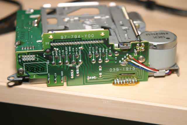
This picture shows how helpfully the PCB identifies what trace carries what signal. We need to break the traces for the Left (L-CH) and Right Channels (R-CH) plus the Audio ground (A-GND) upstream of the solder blobs (we will use those blobs to attach a cable to). You can break the traces by just scraping through them with the tip of a knife or some other sharp object (a jewellers screwdriver is ideal). You can see where I’ve done this in this closeup (note that I was a bit careless and let the knife slip a little).
6. Attach a line out lead to the cassette unit PCB.
I just used a cheapo phono patch cord and cut one end off it. Carefully strip the cable. Wind the braided sleeves from the left and right channels together and tin them with a soldering iron. Strip the insulation off the left and right signal leads and tin those also.
It is easier to keep the leads about one inch long at this stage. You can cut them to the correct length now (for the A-GND lead) or after you’ve soldered them in position (for the L-CH and R-CH signal leads). It is very easy to attach the leads to the solder blobs on the cassette unit PCB as long as you’ve tinned them properly and everything is clean (I find a tiny amount of plumbers/corrosive flux aka soldering paste helps but you must clean any residue off the PCB when you’ve finished)
Here is a picture of the cassette unit with the line out attached.
7. Threading the cable out the back of the headunit
If you used a cheapo patch lead like me the plugs should be small enough to feed through the various holes in the metalwork. If you used some nice shiny audiophile leads with big plugs my apologies because I should have warned you to feed the cable through first before you soldered it in place.
There is a metal bulkhead just behind the cassette unit This has a suitable hole on one side. You can see the cable fed through it here (this picture is taken with the satellite board that contains the Nav interface removed for ease of access. It is attached with two screws at the back, you’ve already removed the right hand one to get the bottom off).
And there is a hole in the back of my headunit covered by a sticky black plastic patch. Peel that off and feed the lead through it. Before you do it might be a good idea to put sort of strain relief in. I did this by just loosely knotting the cable just before it exits the case.
8. Reassemble everything
In the reverse order that you took it out; so:
Fasten the cassette unit back with the four screws
If you removed it put the Nav daughterboard back but don’t screw it in until you’ve put the bottom back on
Push the bottom plate back on and insert all screws (at this point fasten the Nav daughterboard back)
Carefully push the front panel back into place. It shouldn’t take much force and should make a nice click when it’s back in position.
You should now have something that looks like this:
9. Testing and use
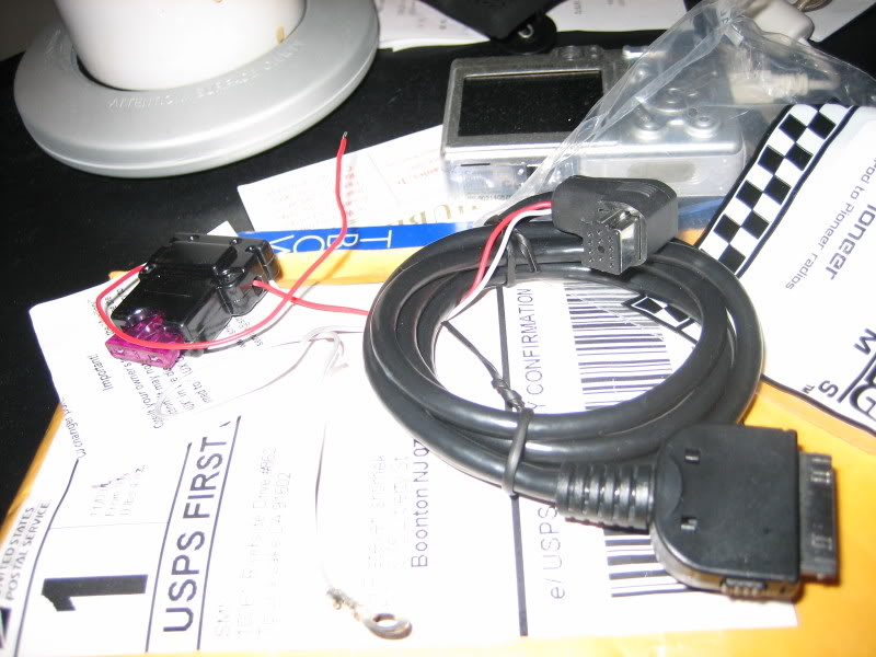
It is probably worth testing that it works before reassembling the dash. I didn’t have a wiring loom for the Bose outside of the 350Z so I just plugged it in and connected the phono leads to a portable iRiver MP3 player. Here is a picture.
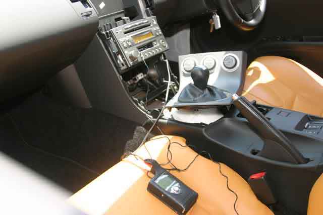
Pressing “Tape” should now activate the line in. But you will need to fool the Bose into thinking that it is playing a tape (or nothing will happen). To do this I simply used a cassette adapter (one of the ones whose sound quality was so bad) with the input lead cut off (the picture is taken before the lead was given the chop, it’s not connected).
It worked perfectly with much better sound quality than either a tape adapter (whose signal has to pass through two tape heads a few amplifier stages and some equalisation to get it to the point where you’ve soldered the leads) or an FM modulator (I tried two, they were both lousy).
I was worried that the input would be very easy to clip and wouldn’t be able to handle line level signals. A definitive judgement will await the arrival of my OmniFi DMP1 MP3 jukebox, but in the test with the iRiver (which is an iPod clone) I wasn’t able to detect any obvious clipping even with the iRiver at very high volumes (at which point the line in was much louder than either radio or CD) so it seems to be useable.
10. Caveats/warnings
This seems to work for me; I don’t use cassette at all so sacrificing it was an easy choice to make. It is pretty easy process (actually getting the dash off was harder) but breaking the PCB traces probably isn’t easily reversible, so be careful. I don’t know what will happen if you cut any of the other traces.
This was done on a 2003 350Z in Singapore – if your Bose headunit is substantially different from the pictures or doesn’t have the helpful labels on each trace or you don’t feel comfortable taking it apart you might want to think about some other route.
Hope that this helps some people.
Regards
Eric
**********************************
Copied from the first page, this is a combined message containing all of the instructions in one easy posting so that it can be copied and printed.
Copied from the first page, this is a combined message containing all of the instructions in one easy posting so that it can be copied and printed.
****************************************************
1. Remove the dash and take the head unit out of it.
The guide here: http://liljerk.morpheus.net/350Z/ is excellent (thanks my350z.com).
2. Remove the front (plastic) panel of the head unit.
It is held on by little clips all around perimeter. You can see two of them in this shot which was taken when I was testing to see if it worked. There are two on each side and three at the top and bottom. Slide a small screwdriver in between the plastic and the metal, gently lever the plastic up from the clip and slide a thin piece of card between the two to allow you to tackle the next one.
All clips done the front panel and the PCB that holds all the front panel controls should come off without much force (if you have to force it, some of the clips aren’t loose)
3. Remove the (perforated) bottom of the head unit.
It is held on by four small Philips screws through the bottom panel, two screws through the back and two screws through the front. All these removed carefully lever the bottom panel off at each side (at the join line) it will take a little force as there are some friction clips built into the side and (I think) the front.
4. Remove the cassette unit.
The cassette unit is now sitting right in front of you. This picture was taken while I was reassembling the head unit but shows where the four screws that hold the cassette unit in are (they’re removed in this picture). To take the cassette unit out just remove these four screws and lift the unit vertically upwards.
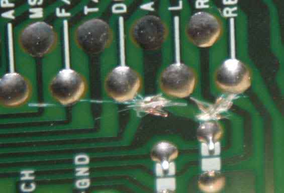
5. Find the correct PCB traces and break them.
If you cassette unit looks like mine the back will look like this. The part sticking up (with 97-794-Y00 written on it) is the connector that plugs into the main PCB.
This picture shows how helpfully the PCB identifies what trace carries what signal. We need to break the traces for the Left (L-CH) and Right Channels (R-CH) plus the Audio ground (A-GND) upstream of the solder blobs (we will use those blobs to attach a cable to). You can break the traces by just scraping through them with the tip of a knife or some other sharp object (a jewellers screwdriver is ideal). You can see where I’ve done this in this closeup (note that I was a bit careless and let the knife slip a little).
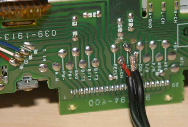
6. Attach a line out lead to the cassette unit PCB.
I just used a cheapo phono patch cord and cut one end off it. Carefully strip the cable. Wind the braided sleeves from the left and right channels together and tin them with a soldering iron. Strip the insulation off the left and right signal leads and tin those also.
It is easier to keep the leads about one inch long at this stage. You can cut them to the correct length now (for the A-GND lead) or after you’ve soldered them in position (for the L-CH and R-CH signal leads). It is very easy to attach the leads to the solder blobs on the cassette unit PCB as long as you’ve tinned them properly and everything is clean (I find a tiny amount of plumbers/corrosive flux aka soldering paste helps but you must clean any residue off the PCB when you’ve finished)
Here is a picture of the cassette unit with the line out attached.
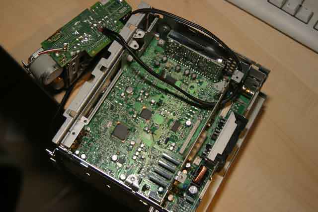
7. Threading the cable out the back of the headunit
If you used a cheapo patch lead like me the plugs should be small enough to feed through the various holes in the metalwork. If you used some nice shiny audiophile leads with big plugs my apologies because I should have warned you to feed the cable through first before you soldered it in place.
There is a metal bulkhead just behind the cassette unit This has a suitable hole on one side. You can see the cable fed through it here (this picture is taken with the satellite board that contains the Nav interface removed for ease of access. It is attached with two screws at the back, you’ve already removed the right hand one to get the bottom off).
And there is a hole in the back of my headunit covered by a sticky black plastic patch. Peel that off and feed the lead through it. Before you do it might be a good idea to put sort of strain relief in. I did this by just loosely knotting the cable just before it exits the case.
8. Reassemble everything
In the reverse order that you took it out; so:
Fasten the cassette unit back with the four screws
If you removed it put the Nav daughterboard back but don’t screw it in until you’ve put the bottom back on
Push the bottom plate back on and insert all screws (at this point fasten the Nav daughterboard back)
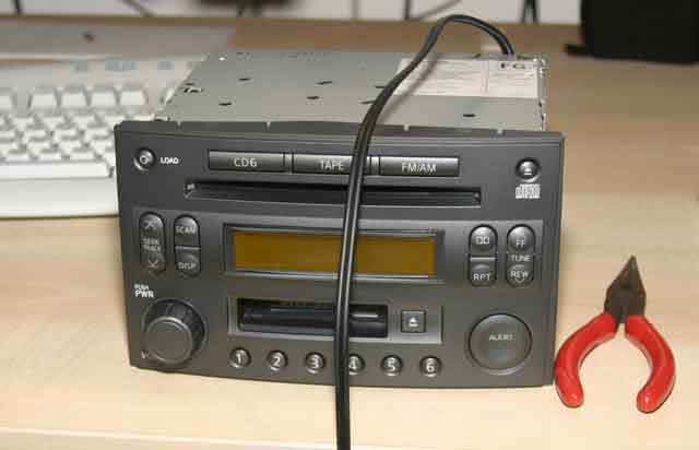
Carefully push the front panel back into place. It shouldn’t take much force and should make a nice click when it’s back in position.
You should now have something that looks like this:
9. Testing and use
It is probably worth testing that it works before reassembling the dash. I didn’t have a wiring loom for the Bose outside of the 350Z so I just plugged it in and connected the phono leads to a portable iRiver MP3 player. Here is a picture.
Pressing “Tape” should now activate the line in. But you will need to fool the Bose into thinking that it is playing a tape (or nothing will happen). To do this I simply used a cassette adapter (one of the ones whose sound quality was so bad) with the input lead cut off (the picture is taken before the lead was given the chop, it’s not connected).
It worked perfectly with much better sound quality than either a tape adapter (whose signal has to pass through two tape heads a few amplifier stages and some equalisation to get it to the point where you’ve soldered the leads) or an FM modulator (I tried two, they were both lousy).
I was worried that the input would be very easy to clip and wouldn’t be able to handle line level signals. A definitive judgement will await the arrival of my OmniFi DMP1 MP3 jukebox, but in the test with the iRiver (which is an iPod clone) I wasn’t able to detect any obvious clipping even with the iRiver at very high volumes (at which point the line in was much louder than either radio or CD) so it seems to be useable.
10. Caveats/warnings
This seems to work for me; I don’t use cassette at all so sacrificing it was an easy choice to make. It is pretty easy process (actually getting the dash off was harder) but breaking the PCB traces probably isn’t easily reversible, so be careful. I don’t know what will happen if you cut any of the other traces.
This was done on a 2003 350Z in Singapore – if your Bose headunit is substantially different from the pictures or doesn’t have the helpful labels on each trace or you don’t feel comfortable taking it apart you might want to think about some other route.
Hope that this helps some people.
Regards
Eric
**********************************
Copied from the first page, this is a combined message containing all of the instructions in one easy posting so that it can be copied and printed.
08-27-2007, 01:04 AM
#99
Registered User

Join Date: Jan 2006
Location: Australia
Posts: 4
Likes: 0
Received 0 Likes
on
0 Posts
awesome!!!! this is exactly what i've been looking for!!! Thanks guys!!
What to do if i want to wire up a ipod ready jack directly though?? like instead of wiring up the RCA and then converting it to a small jack that fits int he ipod, can we just wire that jack directly to the cassette player??
i think those jacks only have 2 wires??
What to do if i want to wire up a ipod ready jack directly though?? like instead of wiring up the RCA and then converting it to a small jack that fits int he ipod, can we just wire that jack directly to the cassette player??
i think those jacks only have 2 wires??