DIY Header/ Hi Flow Cat Installation
 09-10-2007, 06:22 PM
#1
I found this DIY on a women's Z site and thought it could help our forum; Yeah, women can rock too~ Enjoy! :-)
http://www.zchickz.com/header1.htm
How to Install NISMO or Fujitsubo Headers and Random Technology High-Flow Cats on a 350Z
You will need:
Metric socket sets, deep, medium, and shallow; 1/4", 3/8", and 1/2"
Ratchets, 1/4" and 3/8" drives
Flexible head ratchet, 3/8" drive
Breaker, 1/2" drive
Extensions, 1/4" and 3/8", various lengths to 2'
Swivels, 1/4" and 3/8"
Full metric box/open end wrench set (make sure you have thin walled box ends)
Phillips and flat-head screwdrivers, various sizes
Pliers, needle-nose, standard, and channel-lock
12 (10 if only doing cats) 1 1/4" bolts with nuts, large flat washers, and lock washers to bolt up the flanges and cat brace
Loc-Tite - use on any non-exhaust nuts/bolts that could loosen over time
Anti-seize compound - use on all nuts used for exhaust components (be careful with O2 sensors - do not get anti-seize on the sensor head)
22mm O2 socket
Floor jack
Jackstands (2)
Coolant drain bucket
Replacement coolant
Trays to hold nuts and bolts
Whiteout to mark steering column alignments
Shop rags of course
Extension/swivel creativity and lots of patience (patience can be replaced by beer)
Optional items:
New header gaskets
New coolant gasket - driver's side hardpipe to engine block fitting
New O-ring where passenger's side coolant hardpipe connects at rear
Heat shield material
Zip ties, large
18mm x 1.5 wideband O2 bungs welded on RT cats, even if you aren't adding wideband, do the bungs now to save yourself time later if you expect to do wideband; use bung plugs 18mm x 1.5
Procedure:
1. Disconnect battery cables (negative first)
2. Remove strut tower bar
3. Remove engine cover
4. Remove enough intake components to provide access to exhaust manifold
5. Jack front end up as high as you can get it and place jack stands
6. Remove front and rear lower engine fairings
7. Drain coolant - loosen the radiator cap and the vent plug at the top rear of the coolant pipes on the passenger side (near the firewall) - it's best to also drain the coolant from the engine block - discard coolant properly (do not reuse)
8. Remove the coolant hoses from the hard pipe on the passenger side of the engine
9. Remove the bracket from the front of the large hard pipe on the passenger side
10. Remove the 12mm bolt below the passenger side hardpipe at the rear - access from the front and use two extensions with a swivel between; it's a tough one
11. Slide the hardpipe out of the fitting with a little twisting and wiggling - save the O-ring if you plan on reusing it
12. Remove the hoses from the driver's side coolant hardpipe
13. Remove the 12mm bolt from the center hardpipe bracket
14. Remove the two 12mm bolts from the hardpipe fitting that goes into the engine block - they're tough to access, so be creative with swivels and extensions - you may find it easier to access from below if you have someone hold the socket on the bolt from above - save the gasket if you plan on reusing it
15. Remove the manifold heat shields on both sides - four 10mm bolts each - they cannot be taken out at this point so just juggle them around so they're out of your way
16. Remove the passenger side and driver side O2 sensor connectors - they're green connectors clipped to the top rear corners of the engine - use a small flat blade to disconnect
17. Remove the brace that runs between the cats
18. Remove the two O2 connectors at the bottom center - green and blue - use a small flat blade to disconnect
19. Remove all four O2 sensors carefully so as not to damage the tips
20. Remove the two exhaust to cat flange nuts on each side
21. Remove the three cat to manifold nuts on each side
22. Remove the three cat to manifold studs on each side - be careful, the cats will drop out and they're heavy
23. Mark the steering column components with whiteout so you can get them put back together correctly (there may be a couple factory markings already there)
24. Disconnect the steering column U-joint and set aside
25. Remove the manifold bolts - six each side - the front ones are the hardest to get to and you may have to get a little creative with a swivel
26. Remove the exhaust manifolds from the bottom - it's a bit of a puzzle because you'll have to twist and turn them a bit to work them out
27. Remove the manifold heat shields - they will not be reused
28. Remove the manifold gaskets - carefully clean them up if you are reusing them, make sure you don't bend them
29. Check all the studs to make sure none of them got loosened - tighten as necessary
30. Replace the manifold gaskets in the correct orientation
31. Work the headers in from the bottom - again it's a puzzle, but it can be done
32. Get all the header nuts started on the studs - Fujitsubos have no problem nuts; piece of cake - NISMOs have two problem nuts; the upper rear on the driver's side is too close to the pipe, so you need a nut with a smaller shoulder; I used one of the cat to manifold flange nuts; this one will be tightened with an open end wrench; the other problem is the bottom center on the driver's side; you will need the thin-walled box end to rotate over the stud; the end of the stud is too close to the pipe
33. Torque all the nuts to 21-23 foot pounds; torque order for both sides is (retorque the two centers after torquing all six nuts):
* Bottom center - top center - top front - bottom rear - bottom front - top rear
34. Reconnect the steering column using your alignment marks (make sure the steering wheel is centered and tires pointing straight) - make sure the top connector bolt has sufficient clearance on the header pipe when the steering wheel is turned (this was a problem with early NISMO headers)
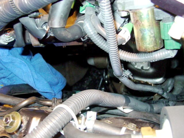
35. With the NISMO headers, you will notice a BIG problem with the fuel line on the passenger side (dangerous!) - the header pipe is right up against the line (see photo) - wrap the fuel line with heat shield material and secure it to the fender well as far away from the pipe as you can get it - you may also want to do some heat shielding on the brake lines (see photo)
36. Reconnect the front O2 sensors - torque to 30-35 foot pounds
37. Bolt up the cats on both ends using the bolts you bought (don't forget the gaskets on both ends) - with the NISMO headers, you may have a problem with the passenger's side since the passenger side header comes off at the wrong angle which puts the cats an inch off at the connector flange with the exhaust; this requires loosening exhaust bolts and some wrenching around to get a good alignment
38. Torque down all the bolts to 30-35 foot pounds
39. Replace the rear O2 sensors - they're color coded for driver (green) and passenger (blue) sides - torque to 30-35 foot pounds
40. Replace the cat brace - the passenger's side cat connection may be a big problem with the NISMO headers; since I was doing the RT cats, I just drilled a new hole in the connector bar on the cat
41. Replace the coolant hard pipes on both sides - use new O-ring and gasket if you bought them; otherwise inspect and clean up the old ones - you may want to put heat shield material on the rubber AC line on the driver's side at this point
42. Replace the air intake components and anything else you disconnected for access to the exhaust manifolds - remember to hook up the MAF sensor connector
43. Replace the engine cover and strut tower brace
44. Replace the under engine fairings
45. Replace coolant drain plugs and fill the radiator and overflow receptacle to cold full
46. Remove the jackstands and lower the car
47. Reconnect battery cables (positive first)
48. Run the engine at idle to circulate the coolant - add more coolant as needed - use the plug at the rear passenger side up next to the firewall to release any trapped air.
Pics:
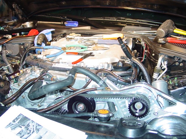
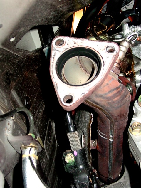
All plumbing on each side of engine removed to provide access to the exhaust manifolds Passenger's side access to manifold
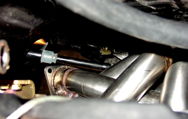
Driver's side access to manifold
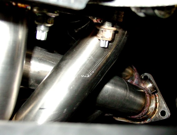
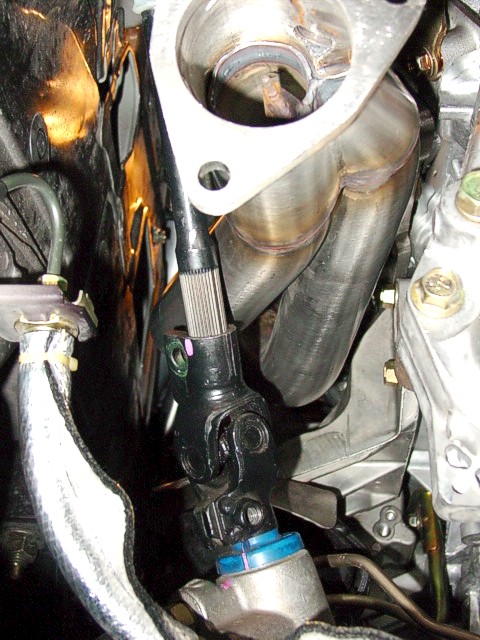
Passenger's side access to manifold
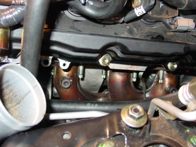
Passenger side before removal of heat shield (4 bolts)
Steering column; mark before disconnecting
Steering column clearance top view
Problem nut, driver's side, top rear
Steering column clearance bottom view
Problem nut, driver's side, bottom center
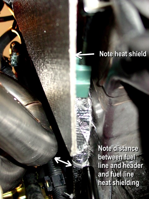
Heat shielding brake and fuel lines
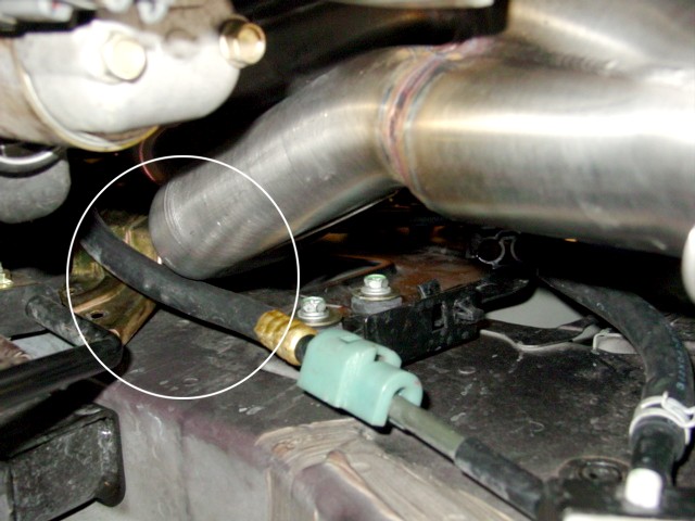
Fuel line clearance issue
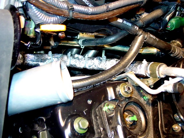
Heat shielding AC line
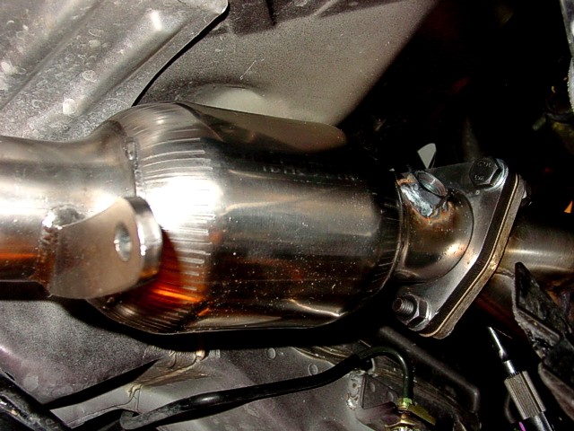
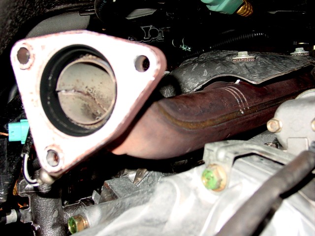
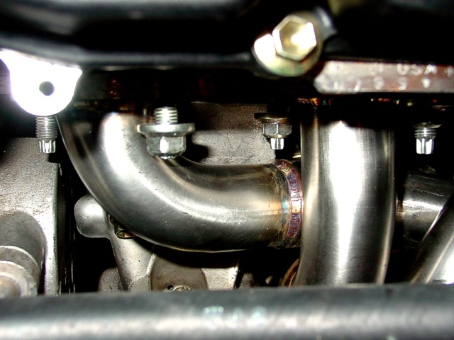
Header and cat married up; note wideband O2 bung
http://www.zchickz.com/header1.htm
How to Install NISMO or Fujitsubo Headers and Random Technology High-Flow Cats on a 350Z
You will need:
Metric socket sets, deep, medium, and shallow; 1/4", 3/8", and 1/2"
Ratchets, 1/4" and 3/8" drives
Flexible head ratchet, 3/8" drive
Breaker, 1/2" drive
Extensions, 1/4" and 3/8", various lengths to 2'
Swivels, 1/4" and 3/8"
Full metric box/open end wrench set (make sure you have thin walled box ends)
Phillips and flat-head screwdrivers, various sizes
Pliers, needle-nose, standard, and channel-lock
12 (10 if only doing cats) 1 1/4" bolts with nuts, large flat washers, and lock washers to bolt up the flanges and cat brace
Loc-Tite - use on any non-exhaust nuts/bolts that could loosen over time
Anti-seize compound - use on all nuts used for exhaust components (be careful with O2 sensors - do not get anti-seize on the sensor head)
22mm O2 socket
Floor jack
Jackstands (2)
Coolant drain bucket
Replacement coolant
Trays to hold nuts and bolts
Whiteout to mark steering column alignments
Shop rags of course
Extension/swivel creativity and lots of patience (patience can be replaced by beer)
Optional items:
New header gaskets
New coolant gasket - driver's side hardpipe to engine block fitting
New O-ring where passenger's side coolant hardpipe connects at rear
Heat shield material
Zip ties, large
18mm x 1.5 wideband O2 bungs welded on RT cats, even if you aren't adding wideband, do the bungs now to save yourself time later if you expect to do wideband; use bung plugs 18mm x 1.5
Procedure:
1. Disconnect battery cables (negative first)
2. Remove strut tower bar
3. Remove engine cover
4. Remove enough intake components to provide access to exhaust manifold
5. Jack front end up as high as you can get it and place jack stands
6. Remove front and rear lower engine fairings
7. Drain coolant - loosen the radiator cap and the vent plug at the top rear of the coolant pipes on the passenger side (near the firewall) - it's best to also drain the coolant from the engine block - discard coolant properly (do not reuse)
8. Remove the coolant hoses from the hard pipe on the passenger side of the engine
9. Remove the bracket from the front of the large hard pipe on the passenger side
10. Remove the 12mm bolt below the passenger side hardpipe at the rear - access from the front and use two extensions with a swivel between; it's a tough one
11. Slide the hardpipe out of the fitting with a little twisting and wiggling - save the O-ring if you plan on reusing it
12. Remove the hoses from the driver's side coolant hardpipe
13. Remove the 12mm bolt from the center hardpipe bracket
14. Remove the two 12mm bolts from the hardpipe fitting that goes into the engine block - they're tough to access, so be creative with swivels and extensions - you may find it easier to access from below if you have someone hold the socket on the bolt from above - save the gasket if you plan on reusing it
15. Remove the manifold heat shields on both sides - four 10mm bolts each - they cannot be taken out at this point so just juggle them around so they're out of your way
16. Remove the passenger side and driver side O2 sensor connectors - they're green connectors clipped to the top rear corners of the engine - use a small flat blade to disconnect
17. Remove the brace that runs between the cats
18. Remove the two O2 connectors at the bottom center - green and blue - use a small flat blade to disconnect
19. Remove all four O2 sensors carefully so as not to damage the tips
20. Remove the two exhaust to cat flange nuts on each side
21. Remove the three cat to manifold nuts on each side
22. Remove the three cat to manifold studs on each side - be careful, the cats will drop out and they're heavy
23. Mark the steering column components with whiteout so you can get them put back together correctly (there may be a couple factory markings already there)
24. Disconnect the steering column U-joint and set aside
25. Remove the manifold bolts - six each side - the front ones are the hardest to get to and you may have to get a little creative with a swivel
26. Remove the exhaust manifolds from the bottom - it's a bit of a puzzle because you'll have to twist and turn them a bit to work them out
27. Remove the manifold heat shields - they will not be reused
28. Remove the manifold gaskets - carefully clean them up if you are reusing them, make sure you don't bend them
29. Check all the studs to make sure none of them got loosened - tighten as necessary
30. Replace the manifold gaskets in the correct orientation
31. Work the headers in from the bottom - again it's a puzzle, but it can be done
32. Get all the header nuts started on the studs - Fujitsubos have no problem nuts; piece of cake - NISMOs have two problem nuts; the upper rear on the driver's side is too close to the pipe, so you need a nut with a smaller shoulder; I used one of the cat to manifold flange nuts; this one will be tightened with an open end wrench; the other problem is the bottom center on the driver's side; you will need the thin-walled box end to rotate over the stud; the end of the stud is too close to the pipe
33. Torque all the nuts to 21-23 foot pounds; torque order for both sides is (retorque the two centers after torquing all six nuts):
* Bottom center - top center - top front - bottom rear - bottom front - top rear
34. Reconnect the steering column using your alignment marks (make sure the steering wheel is centered and tires pointing straight) - make sure the top connector bolt has sufficient clearance on the header pipe when the steering wheel is turned (this was a problem with early NISMO headers)
35. With the NISMO headers, you will notice a BIG problem with the fuel line on the passenger side (dangerous!) - the header pipe is right up against the line (see photo) - wrap the fuel line with heat shield material and secure it to the fender well as far away from the pipe as you can get it - you may also want to do some heat shielding on the brake lines (see photo)
36. Reconnect the front O2 sensors - torque to 30-35 foot pounds
37. Bolt up the cats on both ends using the bolts you bought (don't forget the gaskets on both ends) - with the NISMO headers, you may have a problem with the passenger's side since the passenger side header comes off at the wrong angle which puts the cats an inch off at the connector flange with the exhaust; this requires loosening exhaust bolts and some wrenching around to get a good alignment
38. Torque down all the bolts to 30-35 foot pounds
39. Replace the rear O2 sensors - they're color coded for driver (green) and passenger (blue) sides - torque to 30-35 foot pounds
40. Replace the cat brace - the passenger's side cat connection may be a big problem with the NISMO headers; since I was doing the RT cats, I just drilled a new hole in the connector bar on the cat
41. Replace the coolant hard pipes on both sides - use new O-ring and gasket if you bought them; otherwise inspect and clean up the old ones - you may want to put heat shield material on the rubber AC line on the driver's side at this point
42. Replace the air intake components and anything else you disconnected for access to the exhaust manifolds - remember to hook up the MAF sensor connector
43. Replace the engine cover and strut tower brace
44. Replace the under engine fairings
45. Replace coolant drain plugs and fill the radiator and overflow receptacle to cold full
46. Remove the jackstands and lower the car
47. Reconnect battery cables (positive first)
48. Run the engine at idle to circulate the coolant - add more coolant as needed - use the plug at the rear passenger side up next to the firewall to release any trapped air.
Pics:
All plumbing on each side of engine removed to provide access to the exhaust manifolds Passenger's side access to manifold
Driver's side access to manifold
Passenger's side access to manifold
Passenger side before removal of heat shield (4 bolts)
Steering column; mark before disconnecting
Steering column clearance top view
Problem nut, driver's side, top rear
Steering column clearance bottom view
Problem nut, driver's side, bottom center
Heat shielding brake and fuel lines
Fuel line clearance issue
Heat shielding AC line
Header and cat married up; note wideband O2 bung
Last edited by gothchick; 09-10-2007 at 06:40 PM.
 10-17-2007, 12:45 PM
#2
Registered User

Join Date: Sep 2007
Location: Einsiedlerhof, DE
Posts: 58
Likes: 0
Received 0 Likes
on
0 Posts
first off goth this is an excellent post about one of the biggest choke points in the z.
thanks i will use this when i go back to do this when my parts come in.
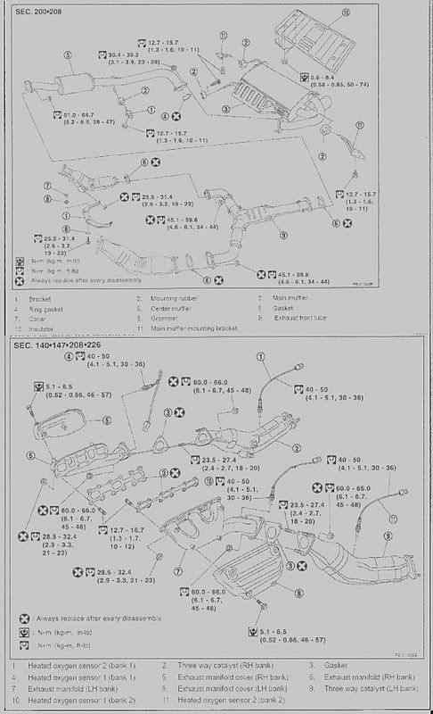
i thought this would help any others that are trying to do this as it has the torque specs from the manufacturer
it is a little hard to see but hey..........
the last numbers at the end of each part are the lbs. per inch you need for a torque wrench. enjoy!
thanks i will use this when i go back to do this when my parts come in.
i thought this would help any others that are trying to do this as it has the torque specs from the manufacturer
it is a little hard to see but hey..........
the last numbers at the end of each part are the lbs. per inch you need for a torque wrench. enjoy!
 11-13-2007, 10:41 AM
#4
Lol!! I wish I could take credit for this great write up! But I found it on another DIY Z site http://www.zchickz.com/header1.htm and thought it could help our 'lil Z community~ :-)
11-13-2007, 02:37 PM
#5

Originally Posted by gothchick
Lol!! I wish I could take credit for this great write up! But I found it on another DIY Z site http://www.zchickz.com/header1.htm and thought it could help our 'lil Z community~ :-)
 12-20-2007, 08:07 PM
#6
Registered User
iTrader: (9)

Join Date: Apr 2005
Location: Houston, TX
Posts: 439
Likes: 0
Received 0 Likes
on
0 Posts
I wish I would've found this before I did my own steps for installing my headers
1) work on my g35 for 8 hours only to give up and put on the stock parts
2) drop it off at a muffler shop and pay them $250 to install my nismo headers
3) drive it home with a bruised ego.
1) work on my g35 for 8 hours only to give up and put on the stock parts
2) drop it off at a muffler shop and pay them $250 to install my nismo headers
3) drive it home with a bruised ego.

Trending Topics


 03-10-2009, 09:16 AM
#11
Banned for NON PAYMENT
iTrader: (6)

Join Date: Apr 2007
Location: Orange County California
Posts: 746
Likes: 0
Received 0 Likes
on
0 Posts
^Maybe use Copper wire tie? good point. even if it doesn't melt right away, It will eventually become brittle and break from being heated and cooled so much.
 06-08-2013, 08:02 AM
#13
Registered User

Join Date: Jun 2012
Location: San Antonio, TX
Posts: 477
Likes: 0
Received 0 Likes
on
0 Posts
So a lot of people may think this is way too much work, but I found that unbolting the a/c compressor provided tons of access to the hard coolant line as well as to the front-lower header nut. The a/c compressor doesn't have to be supported by anything and the lines will flex with it. I was fed up with trying to figure out how to get a swivel on the coolant line, so I thought "Hmmm, a/c comp is in the way..." To get the a/c comp. back on, I supported it with zipties so that the bolt holes were lined up...it makes it so much easier.
Last edited by bmyles; 06-08-2013 at 08:03 AM.
 03-06-2015, 04:36 AM
#16
Registered User

Great write up! But I really would like to see a girl do this job.. definitely not one of the easier installs but then again, having petite hands would help some...
04-22-2018, 01:18 AM
#17

Want to update this for everyone.
Any nismo header design (ebay, topspeed, dcsports, etc) will install this way.
However if you have CRAWFORD headers they are a different design and have much longer runners....
The passenger side engine mount BRACKET must be removed. Starter must be moved out the way. Fuel line and EVAP line must be moved out the way. Engine must be raised a certain amount (too tall too short and it will not clear). Once engine is raised it must be shifted towards the driver side to allow even more clearance. WHY? Because it rubs against the chassis rail...we managed to shove it in this way.
This is specifically for Crawford headers.

Thread
Thread Starter
Forum
Replies
Last Post