When you click on links to various merchants on this site and make a purchase, this can result in this site earning a commission. Affiliate programs and affiliations include, but are not limited to, the eBay Partner Network.
I will do my best to explain the best I can. I did search and I didn't find anything pertaining to my set up. I just don't want to screw anything up. I have a Greddy TT kit and I have my compressors tapped. Originally I talked to tech support at Greddy and did what he told me to do but idk I'm questioning it.
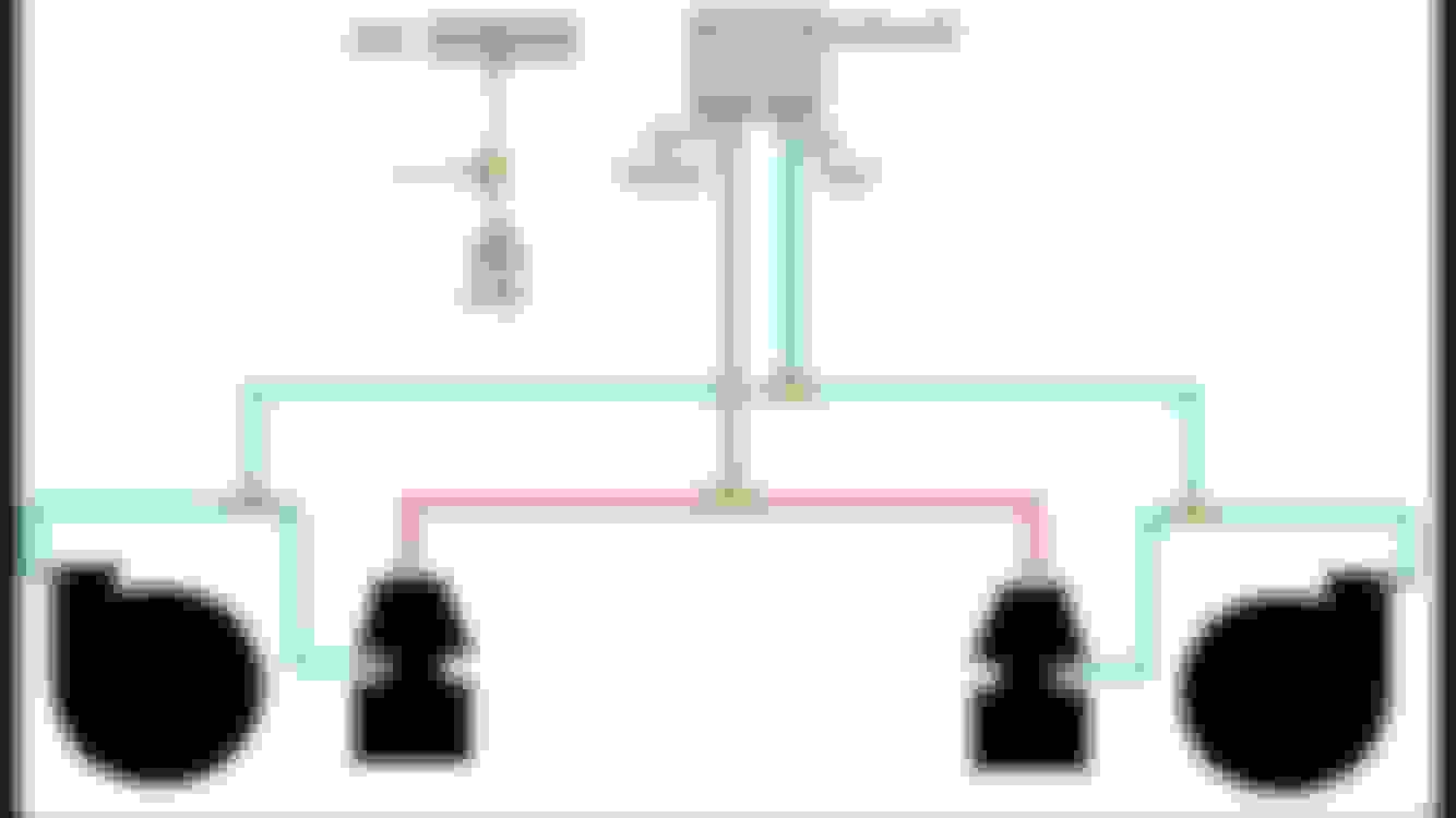
I was told that the compressors and the ports on the sides of the waste gates go together and then run to port 3 on the solenoid. The top ports on the waste gates run to a 3 way fitting then ran to port 2 of solenoid. The thing is on the ports on the side of the wastegates they say to run them to not only port 3 but also to a vacuum source and to use a second 3way fitting for that. They don't have any info in the manual for fittings on the compressors. So is the compressors considered a vacuum source? I don't think it is. Ugh so confused!!! Here's a horrible diagram I drew up. This is how I have it ran. The way tech support told me to run it but it doesn't make sense. The manual says nothing about doing it this way. Can somebody please help me out?
How I have it: compressors to a 3 way, small line to a 4 way that the side ports of waste gates go to as well then ran to port 3. Top of waste gates to a 3 way to port 2. Controller box vacuum line ran to my vacuum block.
I was told that the top ports go to a vac/boost source such as the compressor housings but if I didnt hook them up that it wouldnt be the end of the world - venting them to atmosphere is fine.
That's how my old manual was set up. I was told by greddy that you have to set up the way they want it for there controller. Meaning them top ports need to be used. After digging more last night I could only find this on a LS1 forum. There using the same controller for a twin turbo twin wastegates. This is the same thing I'm running just plumbing is different, but same senecio. I would like to hear if anyone else has input on this tho
1. Google "poppet valve" and read how they work
2. Top port is only used if you want to go to higher boost than the wastegate or if you want to spool up to WG a bit faster
3. Bottom port should be referenced to a pre-tb vac/boost source (say a single fitting in your intake pipe, t'd out)
4. Do not rely on the boost valve port numbers..they can be reversed depending on manufacturer. Look for the NO/NC and vent
5. Boost source to the boost valve should be off your intake manifold, post TB.
The reason you want to run the source for the Boost Valve off the intake is so that when you let off the gas and your TB closes, the vacuum allows the Wastegte to open and bypass the Turbo preventing surge
The reason you want to run the source for the lower port on the Wastegtes is so that when you let off the gas and your TB closes, the excess boost pressure that the BOV is going to release will also help open your Wastegtes..preventing surge.
I do not see the point of tapping off the turbo outlet itself unless you are running your turbo to near peak efficiency. When i think about boost...i want the POST ic boost drop as reference..not the pre. That way my MAP sensor in the manifold reads the same PSI as the boost controller. This might induce some lag in response but I'm not too concerned.
When u say boost valve are you referring to the control unit? Not the silenoid. The control unit needs to see vac/boost after TB. As install says. As far as the waste gate yes I am going to be push passed what springs are in the gates. I do know for sure that greddy did say I needed to use both top and sides for there controller. My question is if the lines are correct and if the compressors can be used for the vac/boost sources that the sides need to see?
solenoid is just the electrical part, we shorthand it. What is really meant by that is solenoid valve.
Boost controller needs the post TB for its control signal.
Call them top and bottom ports.
Top needs the output from the bc solenoid valve
Bottom needs the pre TB boost ref.
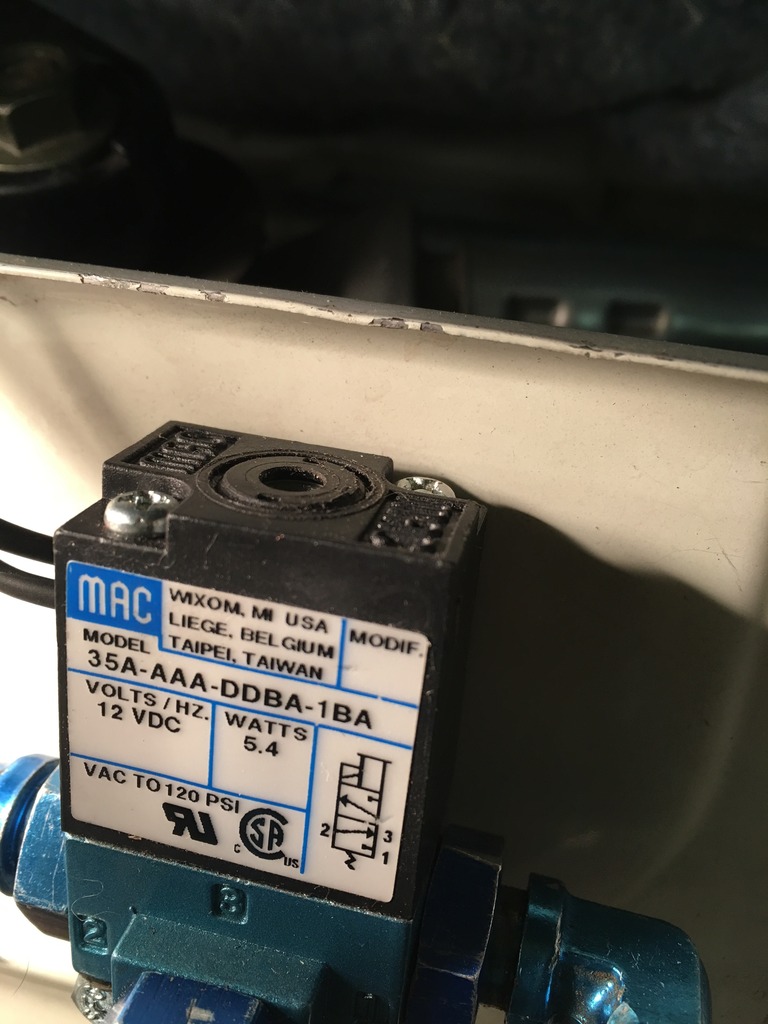
You want the plumbing to be that when the bc solenoid valve is off...no boost is going to the wastegate...so NC. (can be either port 1 or 2 depending on how your valve is built. Most people use a standard MAC brand valve)
You want the plumbing to be that when the bc solenoid valve is off...the top port is vented to atmosphere (typically port 3 with breather filter)
solenoid is just the electrical part, we shorthand it. What is really meant by that is solenoid valve.
Boost controller needs the post TB for its control signal.
Call them top and bottom ports.
Top needs the output from the bc solenoid valve
Bottom needs the pre TB boost ref.
You want the plumbing to be that when the bc solenoid valve is off...no boost is going to the wastegate...so NC. (can be either port 1 or 2 depending on how your valve is built. Most people use a standard MAC brand valve)
You want the plumbing to be that when the bc solenoid valve is off...the top port is vented to atmosphere (typically port 3 with breather filter)
Thanks for verifying that. That is how I have it ran then. And yes mac valve is what it is. Only difference is 2/3 ports. 1 is used for venting. I put a small filter on that port. Thanks again. Yea I just want to make sure I have it correct. Something like this can be dangerous to an expensive build. Ugh.
^yeah, I came across MAC's write up and it was difficult. I took the solenoid off the car and at 0 volts port #2 and port #3 were open and at 12 volts port #2 and port #1 were open. It followed your description above - much appreciated btw.
I'm currently searching - but do you have any good resources to explain how to setup the boost controller within the haltech? Such as the frequency? Start Duty Cycle? Proportional? Integral? Derivative?
I'm currently searching - but do you have any good resources to explain how to setup the boost controller within the haltech? Such as the frequency? Start Duty Cycle? Proportional? Integral? Derivative?
I'm currently searching - but do you have any good resources to explain how to setup the boost controller within the haltech? Such as the frequency? Start Duty Cycle? Proportional? Integral? Derivative?
I'll post-up anything I come across -
Seems like even haltech has a hard time explaining and tuners struggle with closed loop.
Open loop vs closed
Open is just setting a base duty cycle through the RPM range to achieve the desired boost..that day. As things change, so will your boost level. I am currently on open loop. 9psi wastegate springs and ~45dc gets me 18.5psi at the manifold.
Closed is based off the open loop tuning. To me it seems you need to try open loop before you can convert to Closed.
Base duty should be mapped to closely match your desired boost pressure and the open loop value. In my case 0dc is 9psi, 45dc is 18.5psi. I do not suspect it will be linear.
Control start offset sets how soon the controller will start to adjust. Ideally it would be at the base duty cycle or near 100% up to that value.
PID ----typically done without the D. P is the proportional gain and should be an order of magnitude larger than the I typically.
When i go to set mine up i will log what the system does during ramp up since i have not seen a good response from haltech about that. Since i want to hit 18.5psi and the control start offset is max 3psi..the haltech better control the solenoid between my wg 9psi and 15 psi. I will also log the duty cycle in open loop in order to make each psi from 9 to 20 and use that in the closed loop.
Think this is from the manual:
Closed Loop Tuning
Basic Closed Loop Setup Procedure
The Basic Setup Procedure is a guide on how to get some basic parameters in place to allow the closed loop boost controller to operate.
It is assumed that all the target boost levels are above the wastegate spring pressure. The electronic boost controller cannot control boost below the wastegate spring pressure.
Choose Closed Loop for the Control Type.
Set the frequency of the Turbo Waste Gate solenoid in the �Frequency� setting. The Haltech waste gate solenoid runs at a frequency of 20 � 30 Hz.
Disable the controller by setting Proportional � 0%, Integral � 0% and Derivative � 0%.
Set the �Control Point Before Target� to the default value of 20 kPa (3 PSI).
Set the �Delay till Boost Control� to the default value of 0.5 sec.
Set the �Target Boost� table at the boost level that you want to run across the whole RPM range.
Set the �Start Duty� to a duty cycle that should get you close to your boost target. Start at a small duty, then slowly increase to avoid overboosting.
Put the engine under sufficient load (i.e. on a dyno) to get it to reach the target boost level. Watch to make sure it does not over boost. View the duty cycle of the wastegate, by displaying the Duty channel of the output that the boost controller is setup on. E.g. If boost control is setup on DPO1, then view Digital Pulse Output 1 Duty. If the boost level exceeds the target boost level reduce the �Start Duty�, if the boost is far away from the target boost level, then increase �Start Duty�. The final value should allow boost to come close to, but just below the target boost level. If Start Duty is set too high, the controller will spike when coming on boost. If it is set too low, then it will start low and slowly rise to the target.
Once you are satisfied with your Start Duty setting, turn on the controller by restoring the Proportional, Integral and Derivative to the following settings:
Proportional - 50%
Integral - 0%
Derivative - 0%
Adjust Proportional until your boost starts to oscillate. Once you find this value, set the Proportional to about half this value. While tuning this value, your boost may still not hit the target boost exactly. This is normal at this stage.
Once you are satisfied with your Proportional setting, start increasing the Integral value until the target boost is close enough to the target level that you wish to run.
Once Proportional and Integral are set, check to see if you have any overshoot when hitting the target. If you have some overshoot, then increase Derivative until that overshoot is minimised. Use caution when increasing Derivative as this setting is very sensitive and should be increased very slowly otherwise, unstable boost control may result.
Setup of the Start Duty Map
If the Target Boost is varying over RPM, or by either a boost trim or gear boost correction then it is a good idea to setup the �Start Duty� table. The Start Duty is closedly related to the target boost, so a different Start Duty for each Target Boost will allow better control over boost levels.
It is assumed that all the target boost levels are above the wastegate spring pressure. The electronic boost controller cannot control boost below the wastegate spring pressure.
Firstly leave the �Use Start Duty Table� un-ticked. Set the entire �Target Boost� table to the lowest desired boost level that you wish to run.
Use the above procedure for setting up Basic Closed Loop Setup Procedure and stop at step 8. Record the �Start Duty Cycle� and the corresponding Target Boost. Increment the �Target Boost� by about 20 kPa (3 PSI) and repeat steps 6 to 8 and record the �Start Duty Cycle� and the corresponding Target Boost again. Repeat this procedure until you reach the max boost that the engine is going to run. You should have a table of Start Duty values against Target Boost levels every 20kPa or 3psi.
Fill out the �Start Duty� table with the data recorded. For the Target Boost Level columns above the highest target that you wish to run, use the highest value Start Duty that you have recorded. For the Target Boost Levels below the lowest target that you wish to run, taper off the Start Duty values below this column until you reach zero duty when at the wastegate spring pressure column.
In the example above, the maximum boost was 140kPa, with the Start Duty values levelled off above this Target Boost. 100kPa is the minimum Target Boost and the Start Duty values below this are tapered off down to around 50kPa.
I know this is off your topic. I have a question. Did a little logging today and did a little pull and seen knock go up to 479 @ 5100 rpm. Do you know what the range is that's normal or where detonation is starting to take place? Not sure about this stuff. Trying to learn and a buddy of mine was helping me, but he didn't know what is ok and what's not on our cars.
seen knock go up to 479 @ 5100 rpm. Do you know what the range is that's normal or where detonation is starting to take place?
(Blind leading the blind??) Does the 479 have a units? A little bit of knock is expected. I don't know that you're going to find a solid answer (for example) from nissan as your car is far from OEM(in a good way).
I think your best bet is to monitor knock if you get a CEL ... I have a verified-stupid-safe set of ignition timing values I got from High Performance Academy to start from. I don't do anything that involves ignition timing during my road tuning.
5. Boost source to the boost valve should be off your intake manifold, post TB.
The reason you want to run the source for the Boost Valve off the intake is so that when you let off the gas and your TB closes, the vacuum allows the Wastegte to open and bypass the Turbo preventing surge
The reason you want to run the source for the lower port on the Wastegtes is so that when you let off the gas and your TB closes, the excess boost pressure that the BOV is going to release will also help open your Wastegtes..preventing surge.
I do not see the point of tapping off the turbo outlet itself unless you are running your turbo to near peak efficiency. When i think about boost...i want the POST ic boost drop as reference..not the pre. That way my MAP sensor in the manifold reads the same PSI as the boost controller. This might induce some lag in response but I'm not too concerned.
What happens with little partial throttle? Isn't very possible having 0 psi in the intake manifold, while 15 psi of compressed air in front of throttle body? That condition is potentially dangerous, your turbo will spin. A lot, and too much.
(Blind leading the blind??) Does the 479 have a units? A little bit of knock is expected. I don't know that you're going to find a solid answer (for example) from nissan as your car is far from OEM(in a good way).
I think your best bet is to monitor knock if you get a CEL ... I have a verified-stupid-safe set of ignition timing values I got from High Performance Academy to start from. I don't do anything that involves ignition timing during my road tuning.
Awesome that you're rig is on the road...
Just started putting some miles on it. Idk if I'm just neurotic and I'm thinking I hear stuff that isn't there or what. My buddy tells me I'm crazy!! I value is opinion and his knowledge,but when I have a large amount of money wrapped up it only eases my a bit. Idk if the solid motor mounts are just transferring a lot of noise that never did before or what. I do know that my valve train is noisier then before with the full Ferrara valve train. Not worried about that. That's expected. All and all car seems to run good. From the little bit I got into it seems to be an animal!!!!! Car seems a lot nastier then last build and I haven't even really got into it.
I am having an issue with the damn stat opening here and there. Yesterday I couldn't get it to open. Logging the info at idle it never when over 200. Driving it dropped to 181-190 degrees. I don't get it!!! Really starting to **** me off. I've done everything I'm stumped at this point. It was 33 degrees here yesterday.
 02-16-2017, 05:44 PM