
O2 Sensor Simulators - Complete Guide


This DIY will help you if you have an SES because you installed test pipes or something similar.
This write up is different than the many other o2 simulator write ups, because this one allows the user to COMPLETELY remove their secondary o2 sensors.
This is a solution for Z owners with any of the following codes: P0037 P0038 P0057 P0058 P0137 P0138 P0139 P0158 P0159
or anyone driving a car with test pipes removed or HFC's that are throwing a check engine light.
PLEASE REMEMBER, THIS IS ONLY FOR THE POST CATALYTIC OXYGEN SENSORS, SENSOR 2 BANK 1, AND SENSOR 2 BANK 2. USING THIS FOR YOUR PRE-CAT SENSORS CAN AND LIKELY WILL CAUSE SERIOUS DAMAGE TO YOUR MOTOR!
That being said, here you go.
Here is my updated version of the schematic:
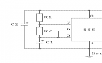
If you compare this to the one from "that other 350z technical forum" or MKIV forums, you will notice that I removed the first diode from the power supply and moved it to the output. This is a small, but VITAL change. The reason I did this was because the current/voltage combination of the 350z (perhaps it was just my Z, but I doubt it) was pushing the limits of the LEDs I was using. what would happen is the simulator would operate properly for a few minutes, and then D1 would either overheat or something, and it then started letting significantly less current and significantly lowered the voltage going into the circuit. This resulted in shifting the oscillating frequency from about once every 3.3 seconds to a much slower frequency and it also lowered the output voltage significantly (to less than 1/3 of the desired voltage). This then triggered another check engine light to come on and ended up causing more problems than you had to begin with. I resolved this by redesigning the circuit with D1 located before D2 on the output wire. As a result, the frequency will drop to about one flash every 3.0 seconds and a stable output voltage.
Parts Needed:
1x NE555 timer IC (or similar 555 timer)
R1 - 100k Ohm resistor (1/4 watt or 1/2 watt)
R2 - 1M Ohm resistor (1/4 watt or 1/2 watt)
R3 - 100k Ohm resistor (1/4 watt or 1/2 watt)
R4 - 10k Ohm resistor (1/4 watt or 1/2 watt)
C1 - 4.7 uF capacitor (rated to at least 15V)
C2 - 22 uF capacitor (rated to at least 15V)
D1 - 1.7V @ 20mA LED
D2 - 1.7V @ 20mA LED
(IMPORTANT: Please make SURE that the LEDs you use are rated to drop 1.7V. If they dont burn 1.7V, then your ECU will have to burn it for them, and that could cause serious damage. They are not simply for appearance!
2x 8 Ohm resistors (Must be 20 watt or greater. I used 8 Ohm because thats what my radio shack had, but anything greater than 4 and less than 10 Ohms should work.)
Edit: I have had this on my car for some time now, with no issues, but I want to suggest very high power rated resistors. The resistors I am using are beginning to degrade due to the heat, so definitely go with at least 25 Watt to ensure they last. And I cannot stress enough, they get EXTREMELY HOT, way hotter than the exhaust, so do not let them rest near anything flammable or plastic.
general tools eg: Duct tape, screw driver, pliers, multi-meter, etc...
Here are the steps:
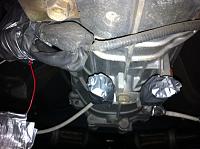
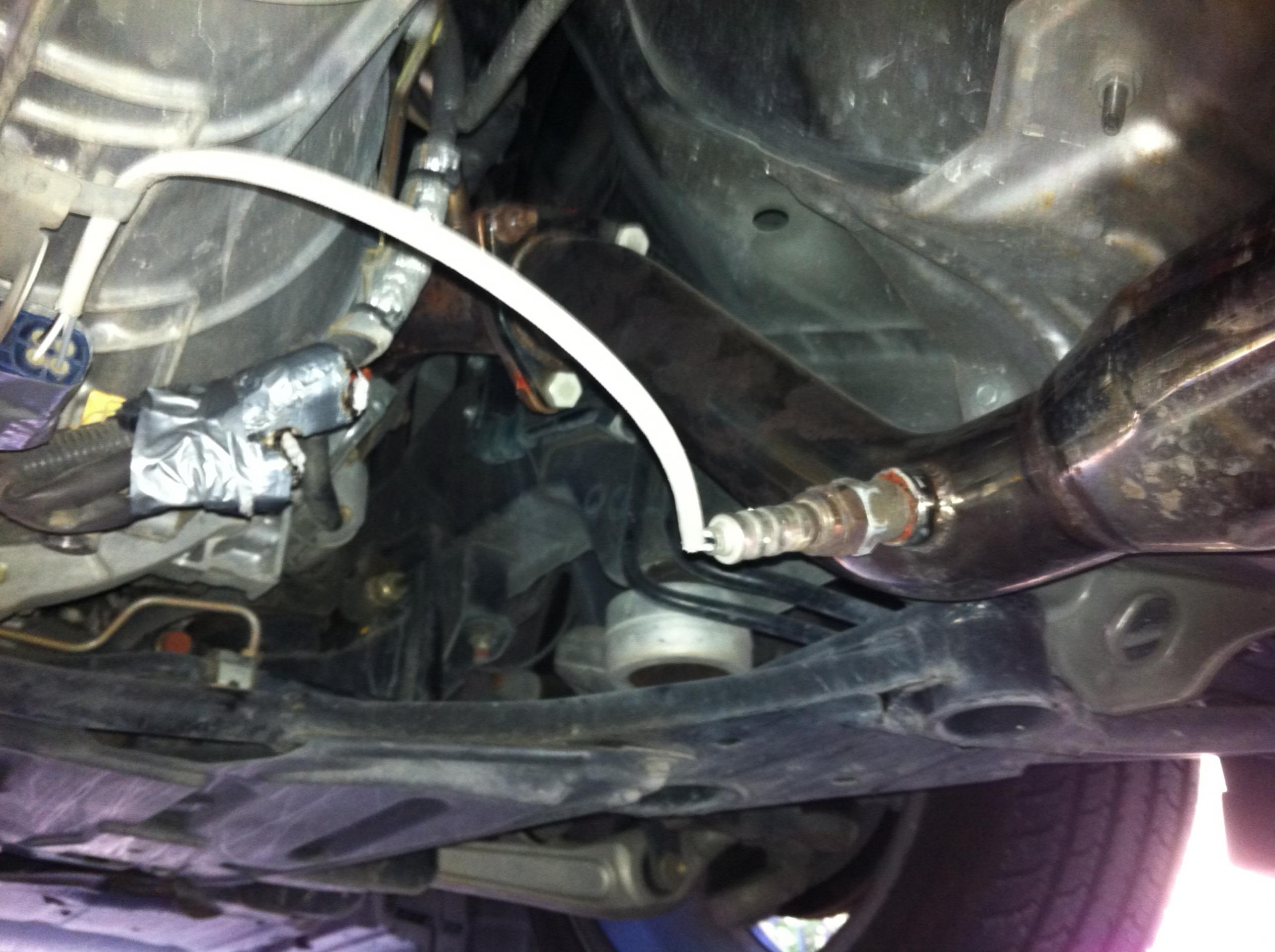
Step 1 - Reach under your car and disconnect sensor 2 on bank 1 and bank 2 from the wiring harness.
These are the two O2 sensors you will be unplugging from the harness.
Step 2 - You may now disconnect your O2 sensors from the car if you choose to. If not, you can still leave them in the exhaust and leave the connectors dangling. I recommend using some duct tape and covering the connectors and taping them up so they dont dangle underneath your car and catch on road debris.
Step 3 - plug two of the 8 Ohm resistors into your o2 sensor harness connector (where the o2 sensor plugs into). *Do this by inserting one side of the resistor into the top left hole of the connecter and then plug the other end of the resistor into the bottom right hole. (Look at the connector with the flat side facing downward and connect between the top left and bottom right holes).
Be sure to plug these into the harness connected to the car, not the plug that is connected to the actual o2 sensor!
Also, these things will get HOT under the car, so stow the actual resistors away from anything heat sensitive. You have been warned. (I am only saying this because I tried this first with two 1 Watt resistors and melted my harness. 20 watt works for me without issue, but if you wanted to be safe and step it up to 25 watt, I wouldnt blame you.)
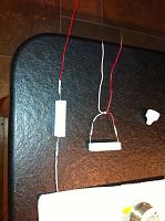
*As you can see in this picture, I soldered a wire to each end of my resistors, then taped them up this way to let me plug the wires into the harness but still keep the resistor a few inches away from the harness.
Step 4 - Repeat step 3, but for the other o2 sensor connecter dangling from the car.
Step 5 - Wrap all of the connectors thoroughly in duct tape to keep water, dirt, and road debris from getting into the connections. Also secure all dangling wires or harnesses so that they are stowed up safely away from road rash. I attached mine to some other wiring that was already under my car, but try to keep them as far away from the transmission as possible to avoid damaging the circuit elements with the heat.
This is how I wrapped up my harness connectors. Do something similar.
Step 6 - I made this have its own step because it is very important. Disconnect the battery from your car. either the power, or the ground, it doesn't matter, just make sure that your battery is not connected to the car.
Step 7 - Now the fun part, haha. You need to tap pins 55 and 74. I did this using wire tap-ins from radio shack and strips of 18 gauge wire. you will also need a power wire. you can do this by tapping into the ecu power wire, pin 119 or 120 (either works), or you can do as I did and run a wire from the cigarette lighter heater (located near the ecu) for a power wire. You will finally need a ground wire. DO NOT USE THE ECU GROUND!!!! Using ecu ground can likely damage your ecu, so beware of that and do not do it!!! Use a wire connected to the chassis of the car. Usually any metal surface of the chassis will serve as a suitable ground. You should now have four wires dangling in your passenger foot compartment: Two signal wires, a power wire, and a ground wire. Be sure to label them so you do not get them mixed up! To get to your ecu harness to tap wires, there are many tutorials on this forum and others showing you how to get into the harness, but essentially it is located in the compartment above the passenger's feet.NOTE: Always disconnect the battery from your car before messing with the ECU. Neglecting to do this can cause serious damage to your ecu.
Step 8 - Solder together the circuit shown above. You can buy a solderable PCB at radio shack and solder all the connections. Be careful when soldering the 555 timer, it is extremely sensitive to heat. I recommend soldering in an IC socket and then plugging the 555 timer in after everything has been soldered, but thats a matter of preference.
Step 9 - Connect the power and ground wires to your circuit, but NOT your signal wires. Reconnect the battery to your car, and turn your car on. Use a multi-meter to measure the voltage between ground and the output. It should change from about 0.0-0.9 volts about every 3 seconds. Also make sure that the current going through the output is never more than 10mA. If your circuit does not deliver those results, you may have soldered something incorrectly or damaged the 555 timer or LEDs while soldering. If you are using a different type of 555 timer, you may have to adjust C1 and R2 to get the frequency correct.
Step 10 - Turn your car off, and connect your signal wires to your circuit's output.
Step 11 - Reset your check engine light. This can be done like so:
Turn your car off and take your feet off the pedals.
Turn the key all the way (but not starting the ignition because your foot is not on the brake) and count out 3 seconds.
Immediately after the three seconds, quickly stomp on the accelerator all the way to the floor and all the way back off the accelerator 5 times in 5 seconds.
Wait 7 seconds.
Stomp on the accelerator and hold for 10 seconds.
Release the accelerator for about 10 seconds.
Stomp on the accelerator again for at least ten seconds.
Turn the car off.
You can now start your car and there will be no check engine light. Timing is critical, so it may take you a few tries to reset your ecu, but I promise it works.
Step 12 - Now that your circuit is connected and your check engine light is reset, drive on happily ever after. If your check engine light comes back on, pull the code. If the code is one of the ones I listed at the beginning of this post, something went wrong while you followed my steps. Make sure that you dont have another check engine code, or that the code you have isnt for another o2 sensor, because those problems cannot be fixed using my tutorial.
Disclaimer:
Please note that I did this on my 2006 350z. The instructions to do this on different models or model years may differ slightly. ALWAYS double check your work when messing with the ecu. Doing this mod, if done poorly, incorrectly, or if something random goes wrong, can damage your ecu. I accept no responsibility if you manage to damage your car, so please understand this and operate carefully.
Enjoy!
Resources:
http://www.mkiv.com/techarticles/oxy...sor_simulator/
http://www.*********.com/wiki/index...._O2_simulators
Factory service manual.
This write up is different than the many other o2 simulator write ups, because this one allows the user to COMPLETELY remove their secondary o2 sensors.
This is a solution for Z owners with any of the following codes: P0037 P0038 P0057 P0058 P0137 P0138 P0139 P0158 P0159
or anyone driving a car with test pipes removed or HFC's that are throwing a check engine light.
PLEASE REMEMBER, THIS IS ONLY FOR THE POST CATALYTIC OXYGEN SENSORS, SENSOR 2 BANK 1, AND SENSOR 2 BANK 2. USING THIS FOR YOUR PRE-CAT SENSORS CAN AND LIKELY WILL CAUSE SERIOUS DAMAGE TO YOUR MOTOR!
That being said, here you go.
Here is my updated version of the schematic:

If you compare this to the one from "that other 350z technical forum" or MKIV forums, you will notice that I removed the first diode from the power supply and moved it to the output. This is a small, but VITAL change. The reason I did this was because the current/voltage combination of the 350z (perhaps it was just my Z, but I doubt it) was pushing the limits of the LEDs I was using. what would happen is the simulator would operate properly for a few minutes, and then D1 would either overheat or something, and it then started letting significantly less current and significantly lowered the voltage going into the circuit. This resulted in shifting the oscillating frequency from about once every 3.3 seconds to a much slower frequency and it also lowered the output voltage significantly (to less than 1/3 of the desired voltage). This then triggered another check engine light to come on and ended up causing more problems than you had to begin with. I resolved this by redesigning the circuit with D1 located before D2 on the output wire. As a result, the frequency will drop to about one flash every 3.0 seconds and a stable output voltage.
Parts Needed:
1x NE555 timer IC (or similar 555 timer)
R1 - 100k Ohm resistor (1/4 watt or 1/2 watt)
R2 - 1M Ohm resistor (1/4 watt or 1/2 watt)
R3 - 100k Ohm resistor (1/4 watt or 1/2 watt)
R4 - 10k Ohm resistor (1/4 watt or 1/2 watt)
C1 - 4.7 uF capacitor (rated to at least 15V)
C2 - 22 uF capacitor (rated to at least 15V)
D1 - 1.7V @ 20mA LED
D2 - 1.7V @ 20mA LED
(IMPORTANT: Please make SURE that the LEDs you use are rated to drop 1.7V. If they dont burn 1.7V, then your ECU will have to burn it for them, and that could cause serious damage. They are not simply for appearance!
2x 8 Ohm resistors (Must be 20 watt or greater. I used 8 Ohm because thats what my radio shack had, but anything greater than 4 and less than 10 Ohms should work.)
Edit: I have had this on my car for some time now, with no issues, but I want to suggest very high power rated resistors. The resistors I am using are beginning to degrade due to the heat, so definitely go with at least 25 Watt to ensure they last. And I cannot stress enough, they get EXTREMELY HOT, way hotter than the exhaust, so do not let them rest near anything flammable or plastic.
general tools eg: Duct tape, screw driver, pliers, multi-meter, etc...
Here are the steps:
Step 1 - Reach under your car and disconnect sensor 2 on bank 1 and bank 2 from the wiring harness.

These are the two O2 sensors you will be unplugging from the harness.
Step 2 - You may now disconnect your O2 sensors from the car if you choose to. If not, you can still leave them in the exhaust and leave the connectors dangling. I recommend using some duct tape and covering the connectors and taping them up so they dont dangle underneath your car and catch on road debris.
Step 3 - plug two of the 8 Ohm resistors into your o2 sensor harness connector (where the o2 sensor plugs into). *Do this by inserting one side of the resistor into the top left hole of the connecter and then plug the other end of the resistor into the bottom right hole. (Look at the connector with the flat side facing downward and connect between the top left and bottom right holes).
Be sure to plug these into the harness connected to the car, not the plug that is connected to the actual o2 sensor!
Also, these things will get HOT under the car, so stow the actual resistors away from anything heat sensitive. You have been warned. (I am only saying this because I tried this first with two 1 Watt resistors and melted my harness. 20 watt works for me without issue, but if you wanted to be safe and step it up to 25 watt, I wouldnt blame you.)

*As you can see in this picture, I soldered a wire to each end of my resistors, then taped them up this way to let me plug the wires into the harness but still keep the resistor a few inches away from the harness.
Step 4 - Repeat step 3, but for the other o2 sensor connecter dangling from the car.
Step 5 - Wrap all of the connectors thoroughly in duct tape to keep water, dirt, and road debris from getting into the connections. Also secure all dangling wires or harnesses so that they are stowed up safely away from road rash. I attached mine to some other wiring that was already under my car, but try to keep them as far away from the transmission as possible to avoid damaging the circuit elements with the heat.

This is how I wrapped up my harness connectors. Do something similar.
Step 6 - I made this have its own step because it is very important. Disconnect the battery from your car. either the power, or the ground, it doesn't matter, just make sure that your battery is not connected to the car.
Step 7 - Now the fun part, haha. You need to tap pins 55 and 74. I did this using wire tap-ins from radio shack and strips of 18 gauge wire. you will also need a power wire. you can do this by tapping into the ecu power wire, pin 119 or 120 (either works), or you can do as I did and run a wire from the cigarette lighter heater (located near the ecu) for a power wire. You will finally need a ground wire. DO NOT USE THE ECU GROUND!!!! Using ecu ground can likely damage your ecu, so beware of that and do not do it!!! Use a wire connected to the chassis of the car. Usually any metal surface of the chassis will serve as a suitable ground. You should now have four wires dangling in your passenger foot compartment: Two signal wires, a power wire, and a ground wire. Be sure to label them so you do not get them mixed up! To get to your ecu harness to tap wires, there are many tutorials on this forum and others showing you how to get into the harness, but essentially it is located in the compartment above the passenger's feet.NOTE: Always disconnect the battery from your car before messing with the ECU. Neglecting to do this can cause serious damage to your ecu.
Step 8 - Solder together the circuit shown above. You can buy a solderable PCB at radio shack and solder all the connections. Be careful when soldering the 555 timer, it is extremely sensitive to heat. I recommend soldering in an IC socket and then plugging the 555 timer in after everything has been soldered, but thats a matter of preference.
Step 9 - Connect the power and ground wires to your circuit, but NOT your signal wires. Reconnect the battery to your car, and turn your car on. Use a multi-meter to measure the voltage between ground and the output. It should change from about 0.0-0.9 volts about every 3 seconds. Also make sure that the current going through the output is never more than 10mA. If your circuit does not deliver those results, you may have soldered something incorrectly or damaged the 555 timer or LEDs while soldering. If you are using a different type of 555 timer, you may have to adjust C1 and R2 to get the frequency correct.
Step 10 - Turn your car off, and connect your signal wires to your circuit's output.
Step 11 - Reset your check engine light. This can be done like so:
Turn your car off and take your feet off the pedals.
Turn the key all the way (but not starting the ignition because your foot is not on the brake) and count out 3 seconds.
Immediately after the three seconds, quickly stomp on the accelerator all the way to the floor and all the way back off the accelerator 5 times in 5 seconds.
Wait 7 seconds.
Stomp on the accelerator and hold for 10 seconds.
Release the accelerator for about 10 seconds.
Stomp on the accelerator again for at least ten seconds.
Turn the car off.
You can now start your car and there will be no check engine light. Timing is critical, so it may take you a few tries to reset your ecu, but I promise it works.
Step 12 - Now that your circuit is connected and your check engine light is reset, drive on happily ever after. If your check engine light comes back on, pull the code. If the code is one of the ones I listed at the beginning of this post, something went wrong while you followed my steps. Make sure that you dont have another check engine code, or that the code you have isnt for another o2 sensor, because those problems cannot be fixed using my tutorial.
Disclaimer:
Please note that I did this on my 2006 350z. The instructions to do this on different models or model years may differ slightly. ALWAYS double check your work when messing with the ecu. Doing this mod, if done poorly, incorrectly, or if something random goes wrong, can damage your ecu. I accept no responsibility if you manage to damage your car, so please understand this and operate carefully.
Enjoy!
Resources:
http://www.mkiv.com/techarticles/oxy...sor_simulator/
http://www.*********.com/wiki/index...._O2_simulators
Factory service manual.
Last edited by DFW Z33; Apr 26, 2012 at 09:57 PM.

Registered User
Joined: Jun 2010
Posts: 10
Likes: 0
From: Fort Benning
Gonna bump an old thread here. I know this allows you to completely remove the secondary O2 sensors but is it necessary to remove them and use the 8 ohm resistors on the harness for the O2 simulator to work???
Sorry for the late reply, but the answer is yes and no. It depends how your sensor fails. Sometimes it will fail in a way that completely changes the sensors resistance. If this is the case, then YES, you do need to use the 8ohm resistor (unless your elctrically savvy and want to build a current sink).
Otherwise, you can most likely leave the sensor and just tap into the two signal wires.
Hope that helps anyone with the same question.
FYI to anyone else, I have received lots of private message questions about this project, but it might be nice to ask them here on this thread also, so other people can see the answers to your questions, and other people may also be able to reply and help you out.
Last edited by DFW Z33; Nov 11, 2012 at 12:51 PM.

Registered User
Joined: Jun 2013
Posts: 9
Likes: 0
From: NH
Hi,
I decided to build this for my 2002 Passat. Do you think the schematic in the link below is more universal?
I also found this schematic -- http://mechdb.com/index.php/O2_sensor_simulator -- but yours is easy to follow and your parts list matches your schematic. The schematic in the other link has more parts in it than the parts list. The parts list in the link and your parts list are the same. The link does mention to test the device before you plug it into your ECU/o2 harness.
Would the LED circuit from a flash light that holds two AA batteries be designed to drop 1.7v x 2 (3.4v total)? Since two AA alkaline batteries are ~1.7 volts when new.
The output signal goes two both of your o2 sensors (I also have a v6 with two o2 sensors).
It looks to me that you made one o2 simulator (or did you make one for each o2 sensor?), but you have two resistors to simulate the heater element for each o2 sensor?
Last edited by jimmy154; Jun 19, 2013 at 05:21 AM.
Hi,
I decided to build this for my 2002 Passat. Do you think the schematic in the link below is more universal?
I also found this schematic -- http://mechdb.com/index.php/O2_sensor_simulator -- but yours is easy to follow and your parts list matches your schematic. The schematic in the other link has more parts in it than the parts list. The parts list in the link and your parts list are the same. The link does mention to test the device before you plug it into your ECU/o2 harness.
Hope that answers your questions, good luck!
Registered User
Joined: Jun 2013
Posts: 9
Likes: 0
From: NH
It does, thanks.
A lot of my questions are actually stupider than they should be.
Just kind of making sure I do everything right.
It's a very good right-up. Written for dumb-asses like me
I'm unsure where to wire the o2 sensor ground (grey wire). I think it can just be wired to the negative terminal on the battery, but I'm not sure. Maybe I'll figure it out while testing. Or maybe it doesn't have to be wired to anything. I'm not sure.
I should know more about electronics than this. Not sure why I just wrote that or what that quite means lol
Also I couldn't get 1.7v LED's at Radio Shack. Closest they had is 1.8v. Maybe I'll try another one, see if they have them. Also I forget what the 1.8v rating was called, but it wasn't "drop voltage".
Last edited by jimmy154; Jun 20, 2013 at 01:46 PM.
It does, thanks.
A lot of my questions are actually stupider than they should be.
Just kind of making sure I do everything right.
It's a very good right-up. Written for dumb-asses like me
I'm unsure where to wire the o2 sensor ground (grey wire). I think it can just be wired to the negative terminal on the battery, but I'm not sure.
The LEDs are there to drop the voltage so that the ECU does not have to take on as much of the power. 1.8V LEDs should work fine, just dont go any lower. The rating may be called "drop voltage" "forward voltage" "bias voltage" or any combination of those. Also, if you have trouble finding an LED that works, you can use a standard diode.
Trending Topics
Registered User
Joined: Jun 2013
Posts: 9
Likes: 0
From: NH
I built three circuits.
None of them oscillate from 0-0.9 volts.
I don't know if it's my DMM or what.
All use different parts except for the LEDs are the same.
But they light up a little, so I think they should be good, but I'm not sure.
Would they have anything to do with oscillation anyway?
I've tried many different NE555's, all do the same thing.
Sometimes they kind of look like they are oscillating for a little while on my DMM, but all stop.
They stay steady at ~.75 volts with the car off and ~.9 with the car on.
Before I added the ground wire from the gray o2 sensor wire to the the battery I measured 8.5-9.8 mA with the car off and on respectively.
But then after I added the wire it's 10-11.5 mA respectively.
the labels you put in this diagram are correct. The +12~+15V is just the positive battery terminal. The ground goes to the negative terminal or any grounded part of the car, like the chassis (Just not the ECU ground). The "out" goes to the o2 sensor input on the ECU. That circuit if connected correctly will oscillate as described. Post an actual picture of your circuit, so I can try to look through your wires and find any mistakes. Also, be sure to read your resistor color codes correctly. If you use the wrong capacitor or resistor values, it could oscillate way to fast or too slow to be seen on a DMM. If you use a different brand 555 timer, the pin numbers on the chip may be different, so just be sure to match the pin names on your brand of 555 with the pin names on the NE555 that I used. These pin names can be found on their datasheets. Just google NE555 datasheet
Registered User
Joined: Jun 2013
Posts: 9
Likes: 0
From: NH
I've checked this thing so many times it's ridiculous. I have the NE555P and NE555N variants. I tried several of both. If looking at the top (pins down) with the notch facing up "1" is to the left of the notch and "8" to the right, correct? I've seen the pins diagrams, they are from the top of the chip I've almost 100% sure.
Last edited by jimmy154; Jul 9, 2013 at 09:39 AM.
Ok, I just checked, and all of your connections are made correctly. Have you double checked which direction your LEDs are connected? If I had to guess, that is your problem. The LEDs can only work facing one direction.

Look at your LEDs and look for the shape of the metal inside the plastic bulb of the LED. Notice one side of the metal is bigger triangle and bends above the other triangle pin. That is the (-) side of the LED. Make sure the LEDs are connected so that the positive side is connected to R3, and the negative side is connected to the positive side of the next LEDs positive side, with that LEDs negative side connected to R4. Basically:
NE555 Pin 3 ---> R3 ---> (+)LED1(-) ---> (+)LED2(-) ---> R4 ---> NE555 Pin 1
Please let me know if this is not the issue. If it still does not work, please send me a zoom in shot of the LEDs and I might be able to see if they are faulty.
Registered User
Joined: Jun 2013
Posts: 9
Likes: 0
From: NH
Hmmm . . . I was just reading about LED's
When I originally made the circuit I made sure I wired the long wire to R3/pin3.
But then the next circuits I made I kind of lost track.
I have more than one set of LED's
They seem to work backwards.
Cathode wired to R3. I read that (unless it's a "jumbo" LED)
the small anvil post is the Anode.
But my LED's seem to work opposite lol WTF
I get some oscillation, but it seems to be really fast.
I measured the circuit before the LED's
Voltage is higher but oscillation is roughly the same, very fast.
Registered User
Joined: Jun 2013
Posts: 9
Likes: 0
From: NH
My LED's flat part is on the other small or "positive" terminal, but the flat part is the negative terminal.
If I'm reading my multimeter correct in the 2 mA setting I get "0.116" max (mA?)
I hope it's not an amp reading because that would be 116 mA of course?!
What should it be?
Also when the circuit is not connected to the o2 signal wire I get .0 to .9 volts, when the car is running. When I connect the signal out to the o2 sensor input of the ECU, I get .22 to .77 volts with the car running. Seems like my wire needs a ground, no? Will it still work?
Are my LED's the wrong mA rating?
Last edited by jimmy154; Jul 10, 2013 at 01:44 PM.
Registered User
Joined: Jun 2013
Posts: 9
Likes: 0
From: NH
Did I wire this right?
So far it doesn't work.
The circuit oscillated from .77 to .2 VDC when the car is on at .116 mA.
The resistors are 10 ohm for my Passat I think.
The blue wires go to the circuit output. The o2 signal wire or black o2 sensor wire goes to the blue wires.
The brown wires go to the battery ground. The o2 sensor ground or grey o2 sensor wire goes to the brown wires.
The pink ones go to the resistors.
Honestly, Im not sure what is going wrong in your case. I just double checked my circuit and it still works here for me, so you must have a misconnection somewhere. I would have to actually see your circuit to see what is wrong with it. There are any number of things. If you use the wrong capacitor, it could start oscillating too fast for your DMM to read.
Also, given that this device is working with your ECU and high power electronics, I suggest you get someone near you who knows electronics to take a look at it. Last thing I want is for you to catch your car on fire or something. Sorry I cant be more helpful.
Also, given that this device is working with your ECU and high power electronics, I suggest you get someone near you who knows electronics to take a look at it. Last thing I want is for you to catch your car on fire or something. Sorry I cant be more helpful.
Registered User
Joined: Jun 2013
Posts: 9
Likes: 0
From: NH
I have a problem with the resistance circuit.
I don't know what resistance the white wires should have wired in. The resistance in the O2 heater sensor seems to go higher that hotter it is.
8 ohms didn't work, then 10 didn't now I have 18 ohms for each circuit.
I measured one of the front O2 sensors and the resistance was 10.7 when warm and 14.5 ohm when pretty hot.
I have codes P0141 and P0161 and P0056, but not P0036, 2 or 3 times the same code came up. P0141 and P0161 is for too low of a heat resistance I think, but I don't know why I get P0056. I assume it's for a bad O2 sensor ground, but I don't know why it's only on O2 sensor.
You are correct. Dont ever use a simulator to replace sensors that are detecting the A/F ratio for ECU fuel mapping. Only use it to replace smog detecting sensors