
Boosted Performance single turbo fabrication


Thank you.
Turbo and waste gates are the only things under the car. They also sit higher than the aftermarket exhausts I have seen
What you are saying is that you would never put an HKS exhaust (which is more than a turbo and two wastegaes) on your car because you fear ???.
Turbo and waste gates are the only things under the car. They also sit higher than the aftermarket exhausts I have seen
What you are saying is that you would never put an HKS exhaust (which is more than a turbo and two wastegaes) on your car because you fear ???.

also as a owner of his kit i will tell you right now you will rip pieces of your sub frame off and pinch welds before you touch the kit. since it sits higher then pretty much everything. only issue i have had with the open waste gate dump is because i have it turned a different way then it was engineered to go, and for my little bit of custom its easy to trim it(supposed to point towards the back of the car i have it pointed straight down.) and even then he offered to replace it. you cannot go wrong with sasha

Thread Starter
Vendor - Former Vendor
iTrader: (14)
Joined: Jan 2010
Posts: 1,782
Likes: 18
From: Edmonton, AB
Bit of an update...not so exciding but I think you guys will take anything.. :lol:
All the oil stuff is done, oil cooler is installed for good, as is the scavenge pump. Turbo oil fed line is also complete, so the front bumper is close to going back on. I have to do a bit of intercooler pipe work first thing in the morning, so that I have a set of charge pipe (engine bay) to keep with me.
On to the pictures:
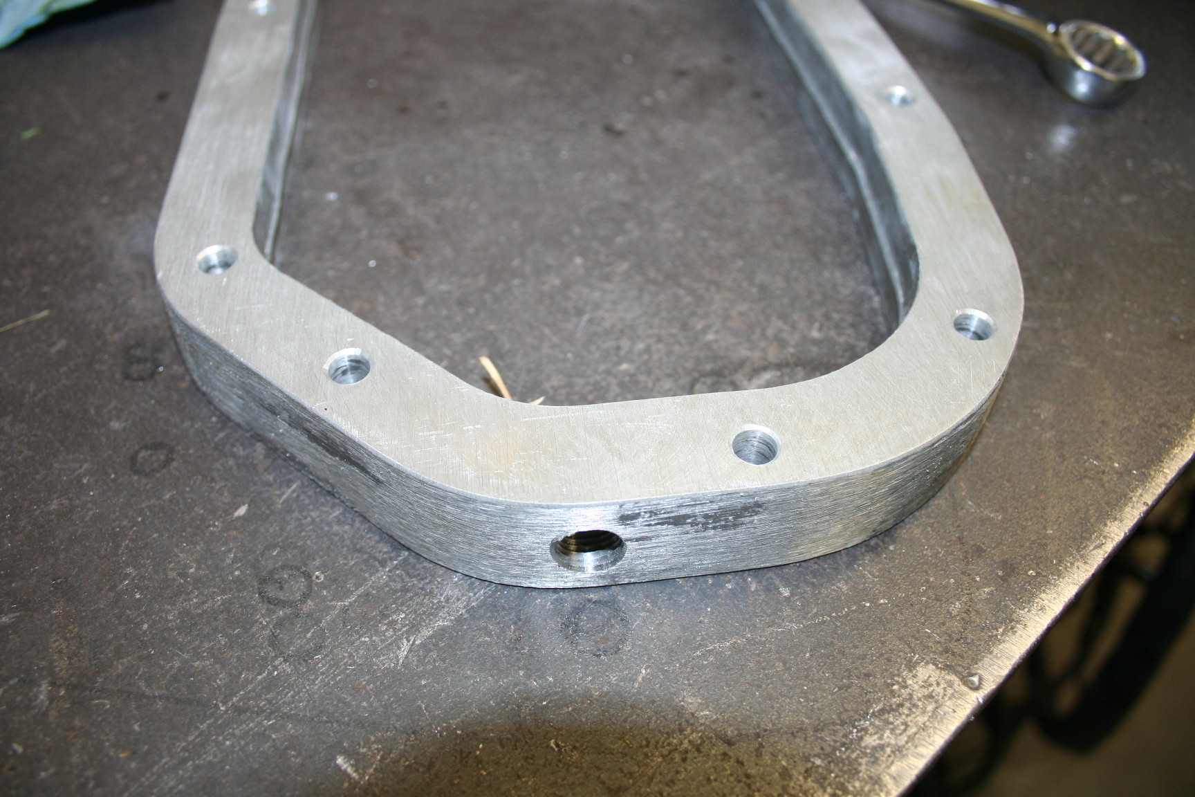
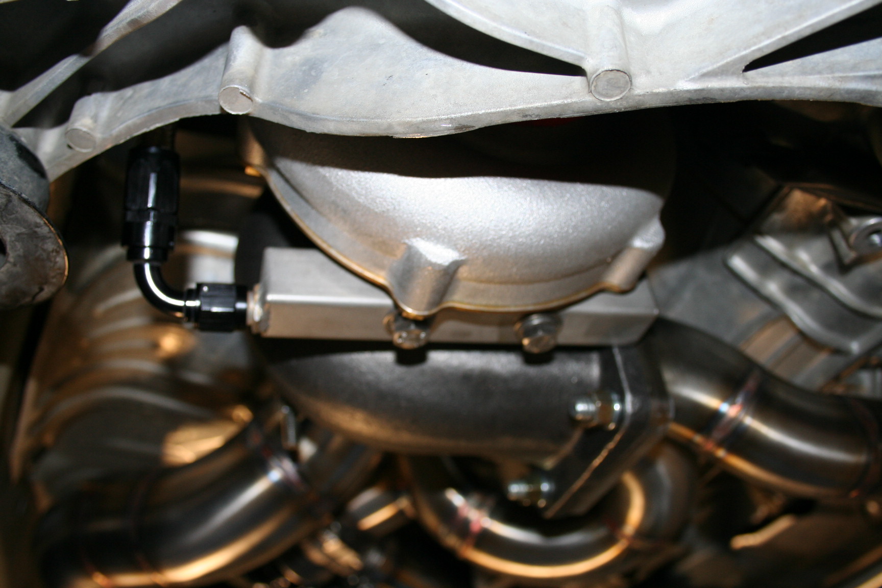
Spacer with oil return port:
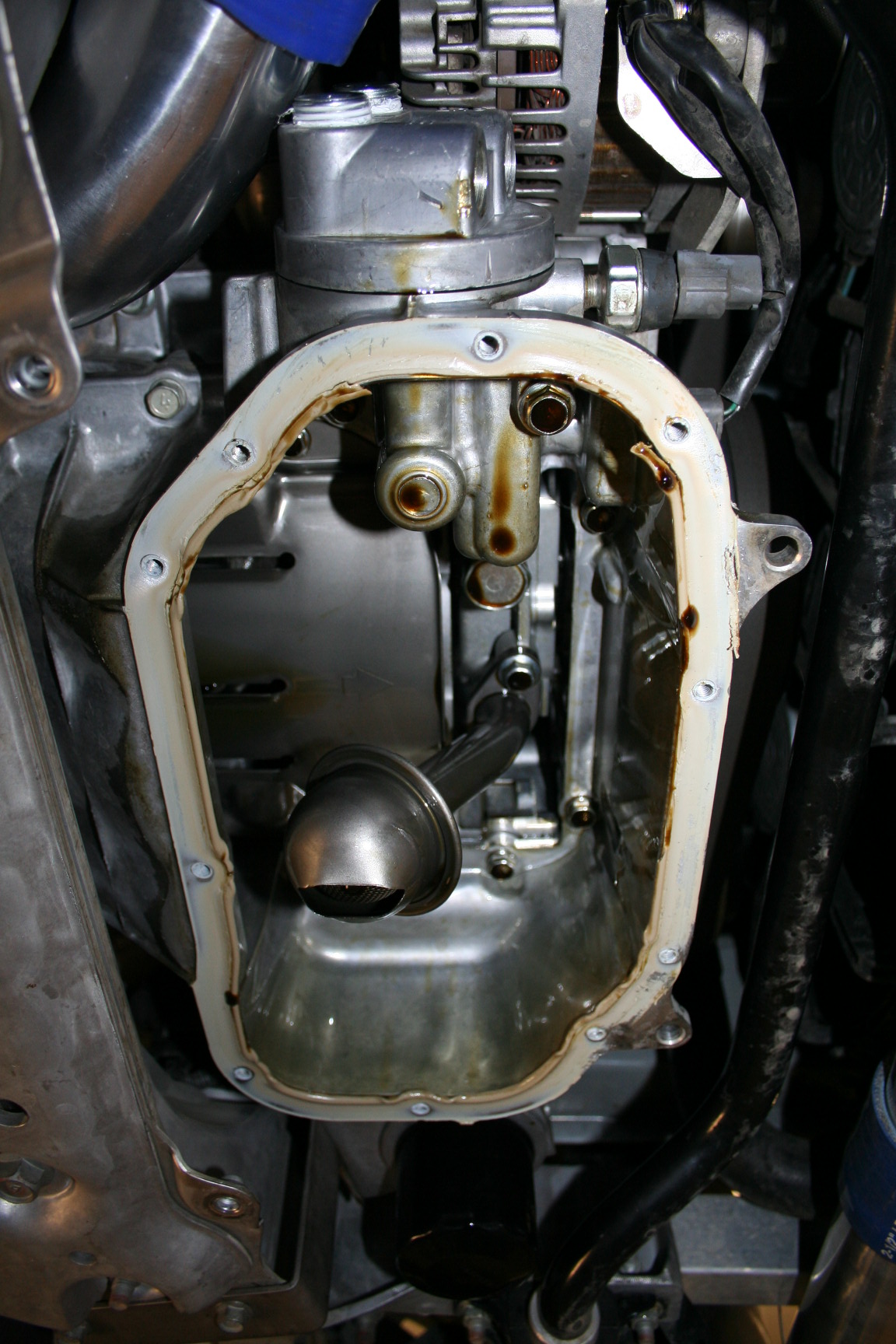
Getting the OE pan off, you got to use a hammer on this:
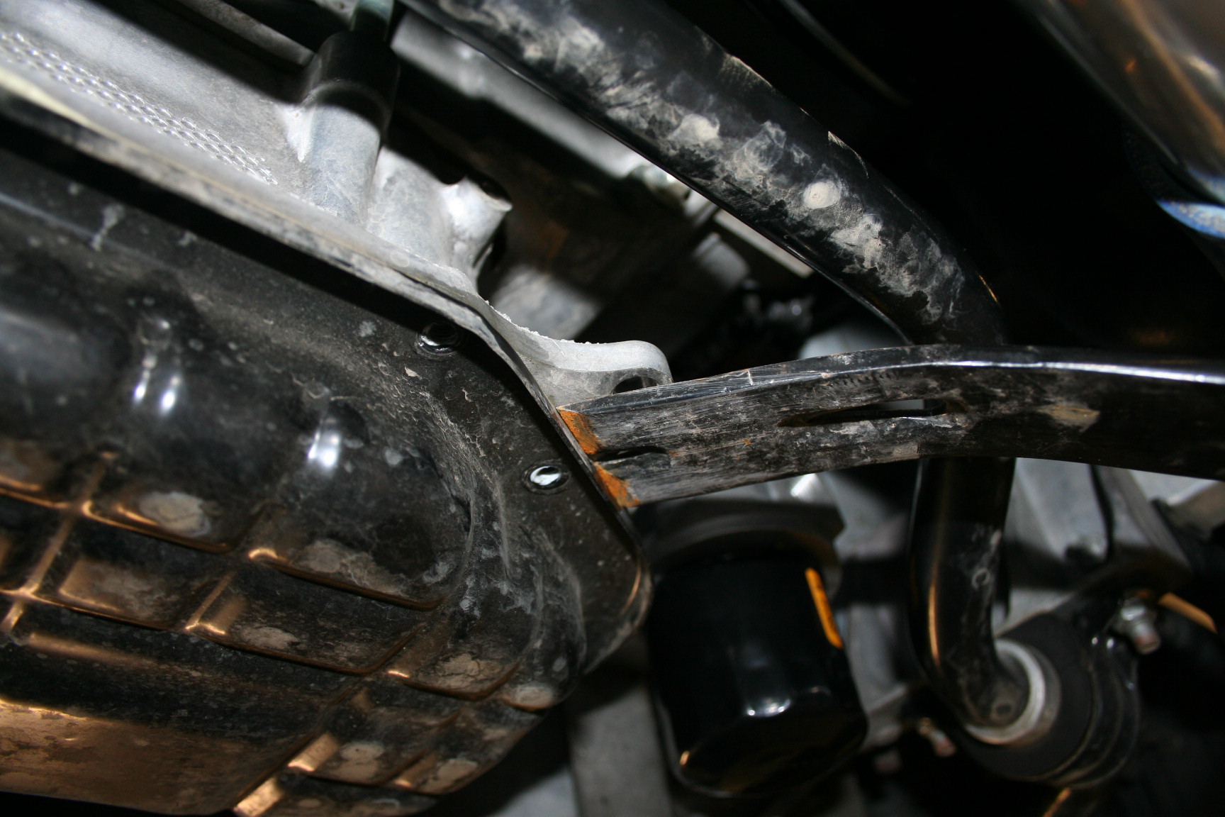
Aaaaan off:
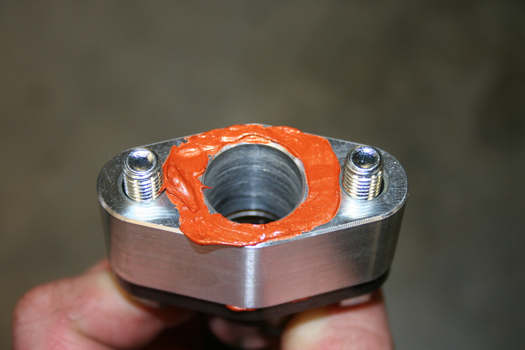
RTV on:
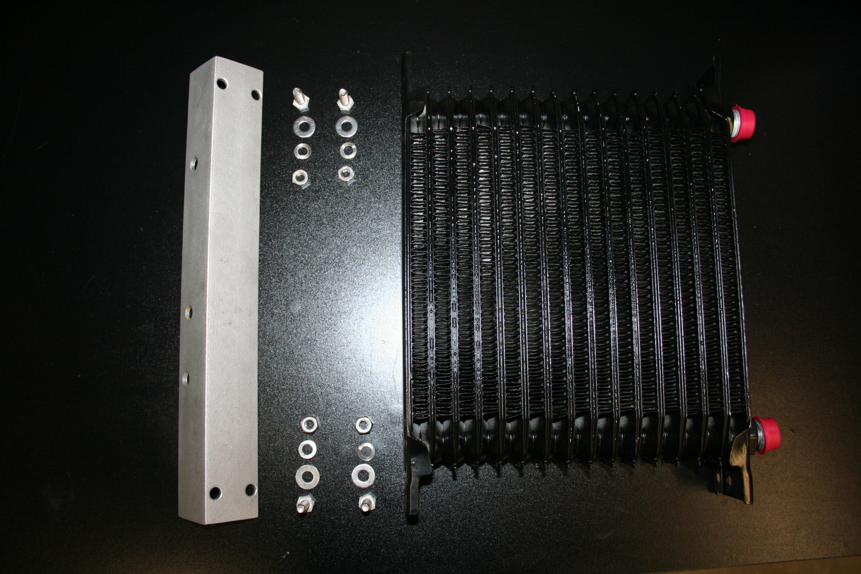
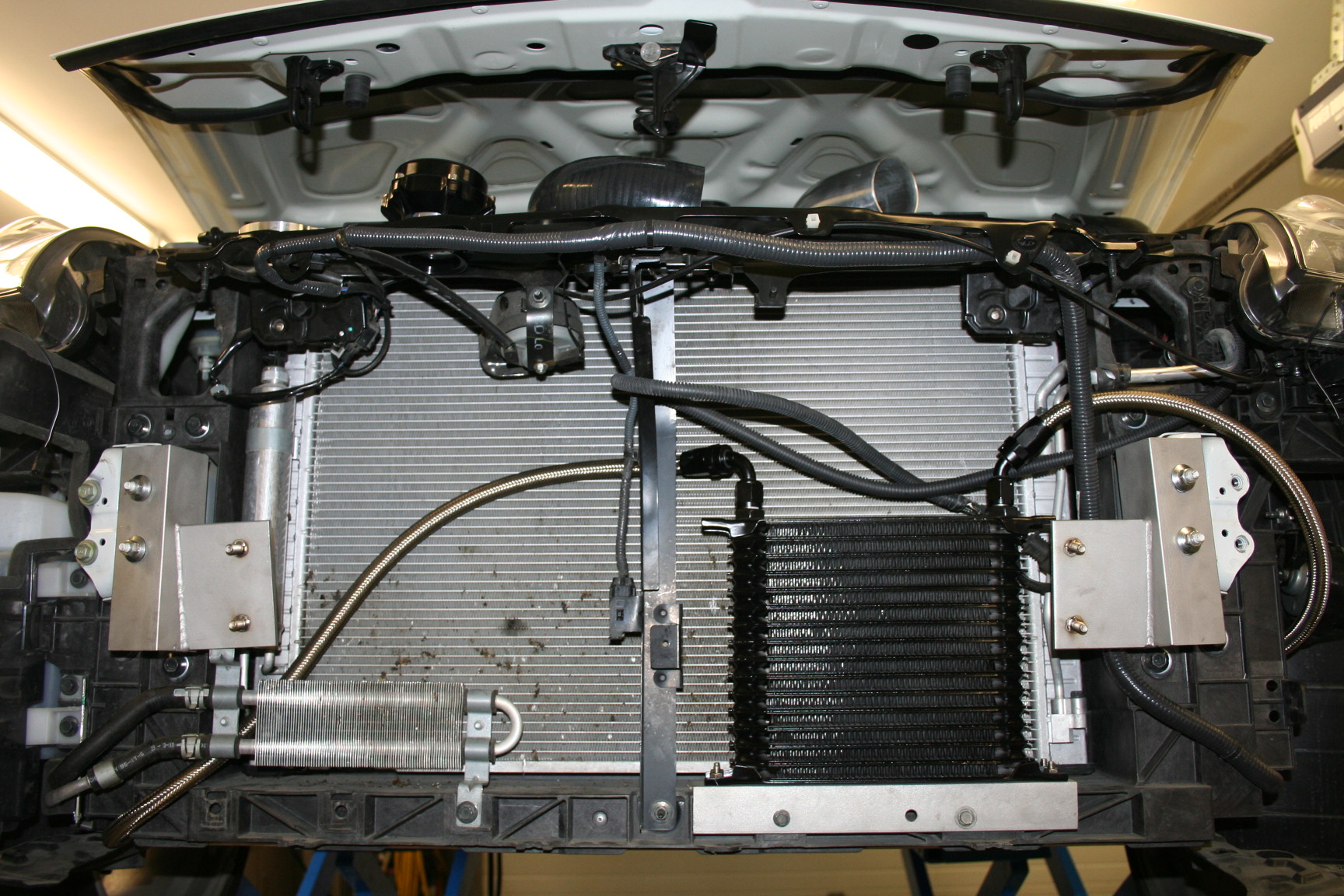
Oil cooler with hardware before assembly:
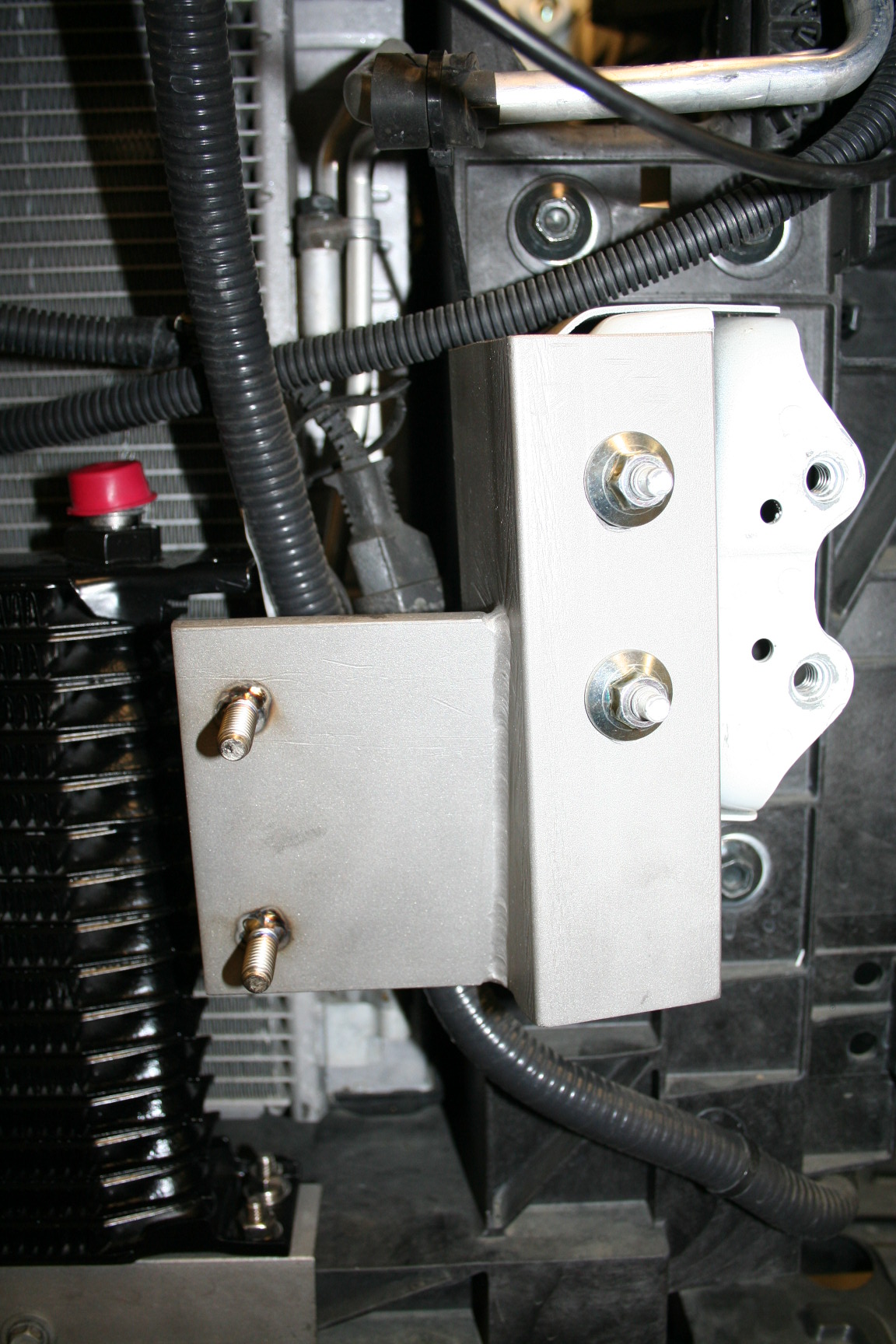
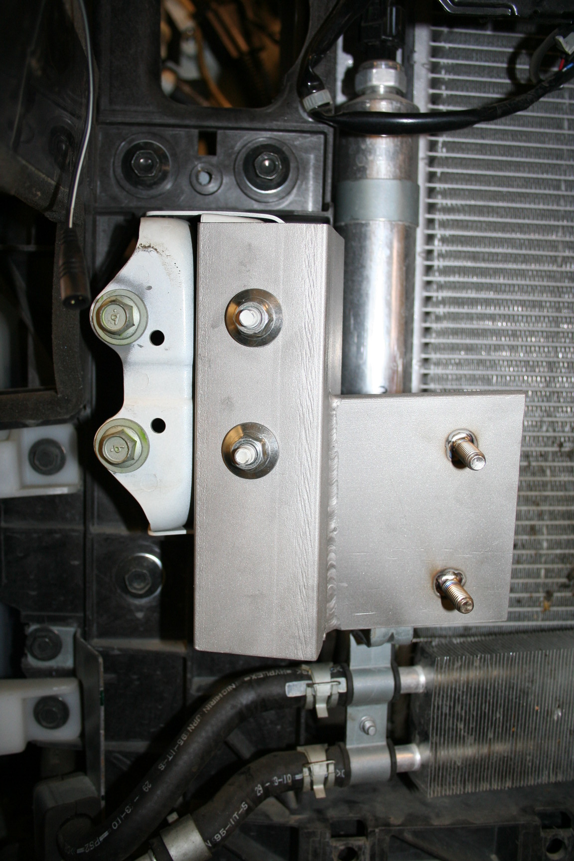
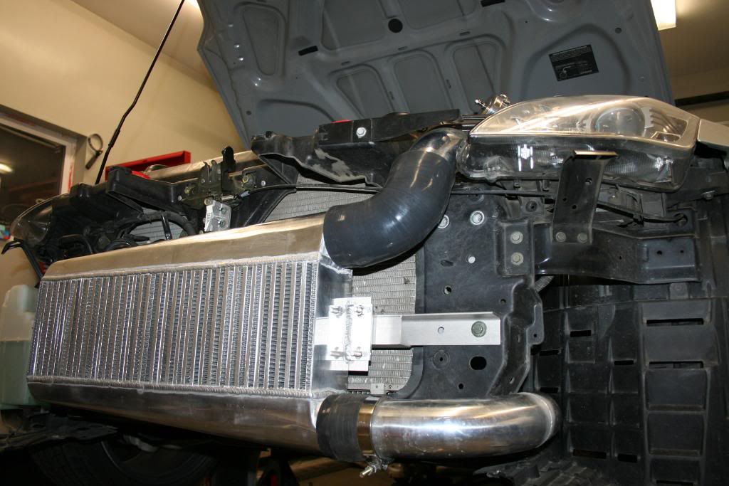
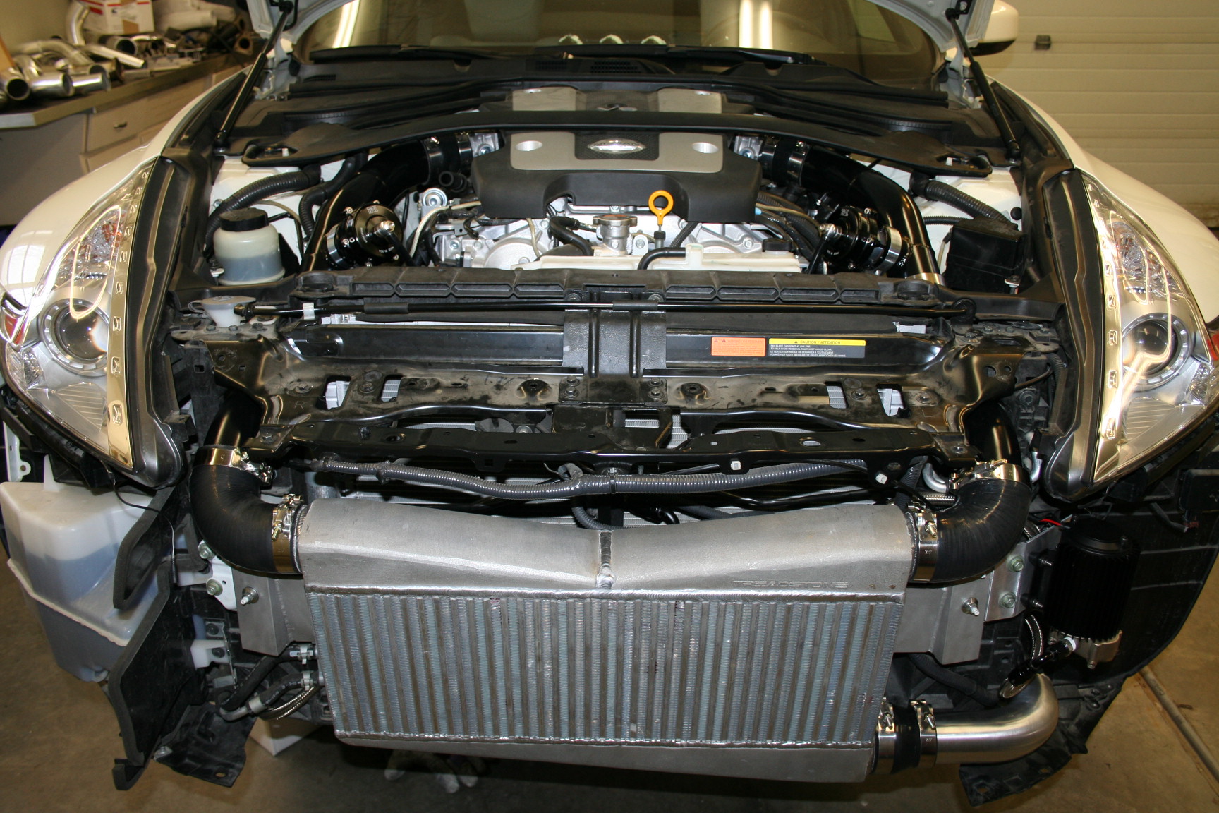
Both FMIC brackets welded solid and bolted on:
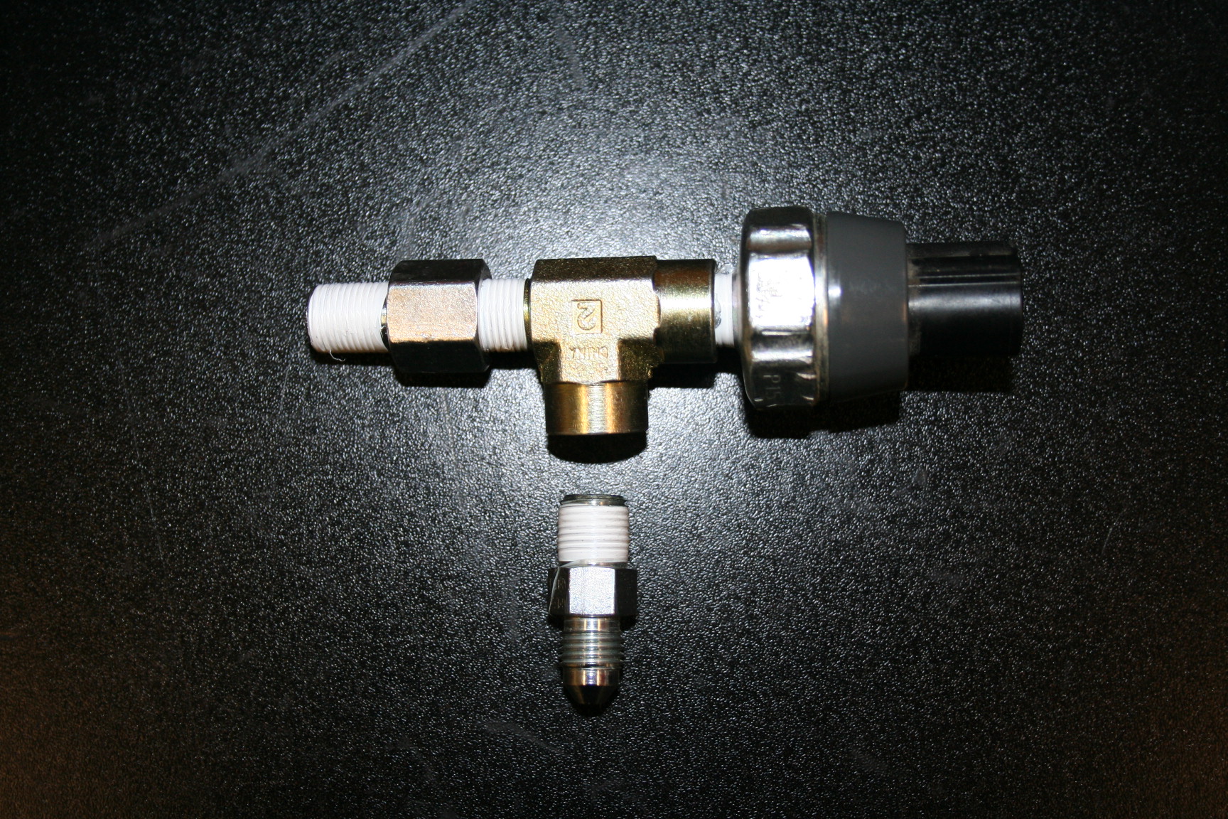
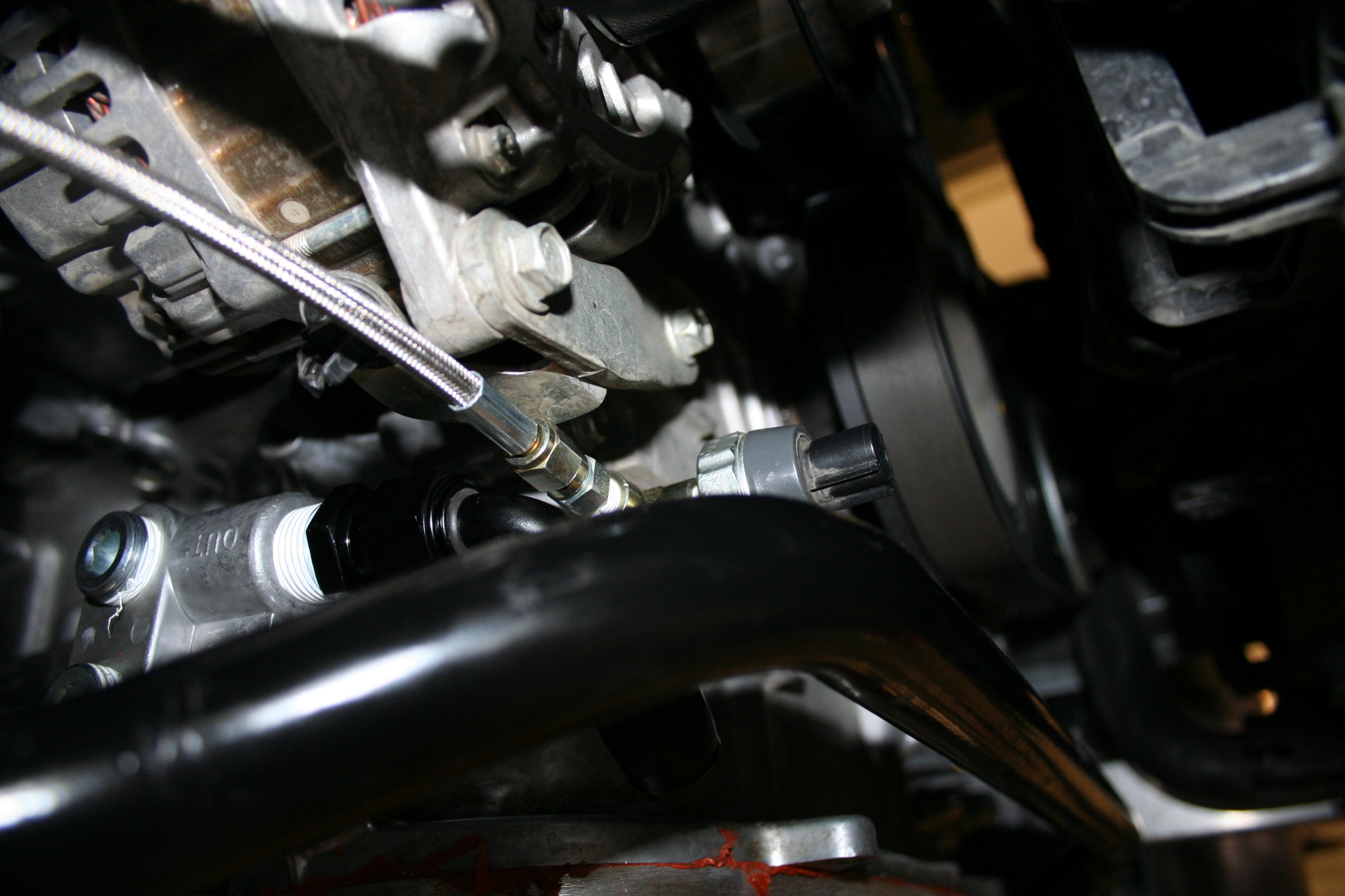
Oil pressure sensor with hardware/adapter for turbo oil feed:
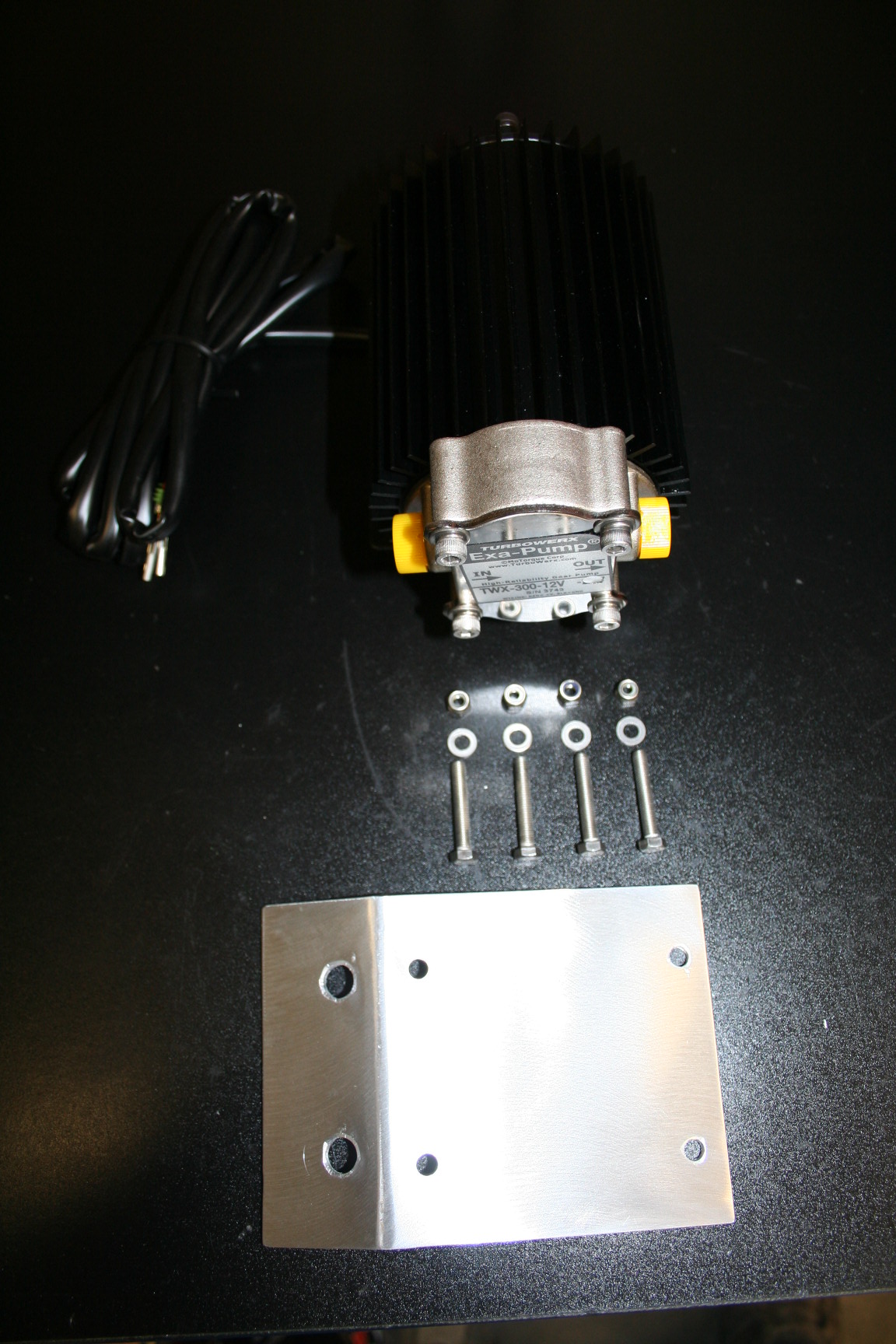
Scavenge pump with hardware ready for assembly:
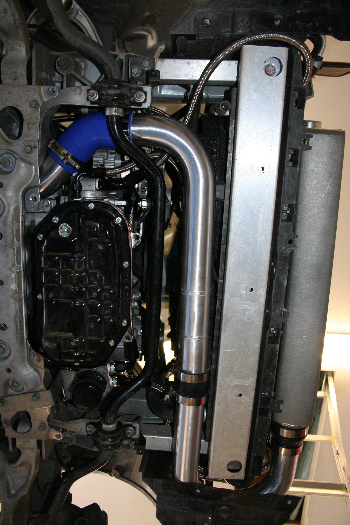
A few oil lines under there:
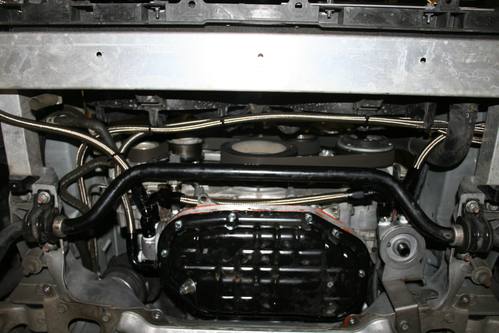
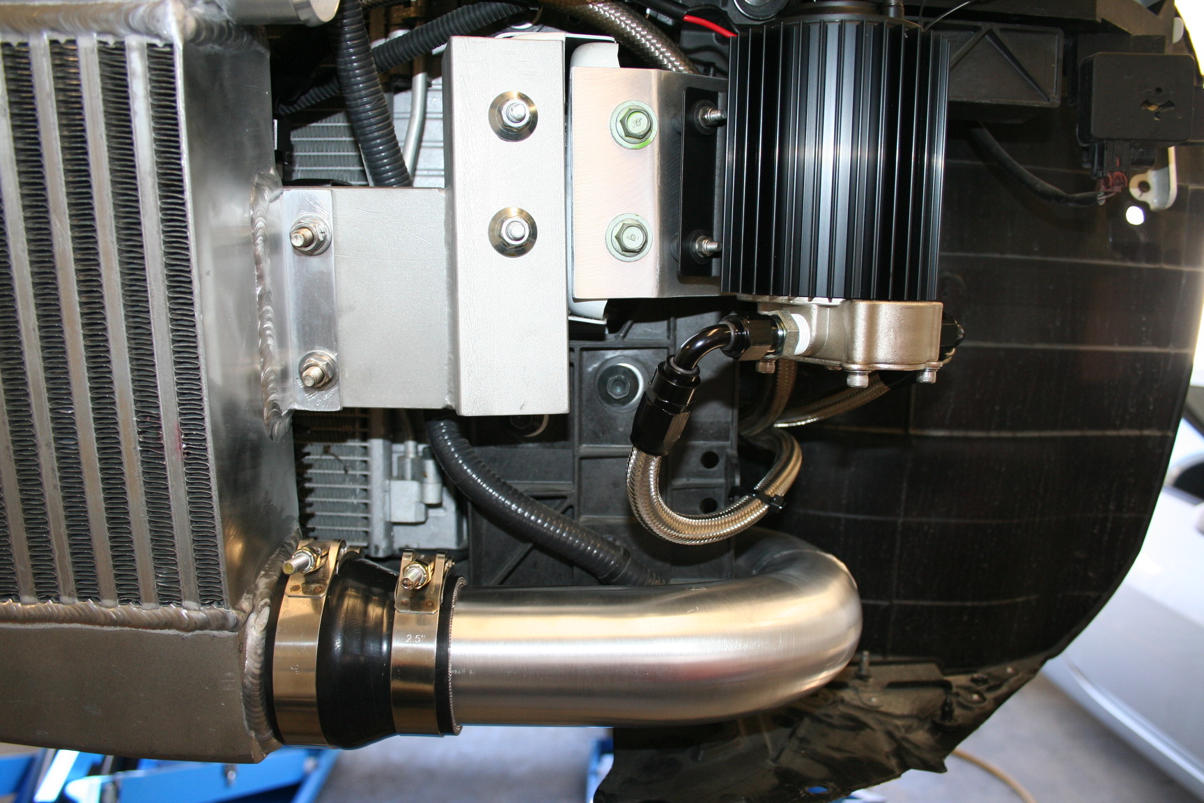
Final install shot of the pump with all hoses in place, tied up
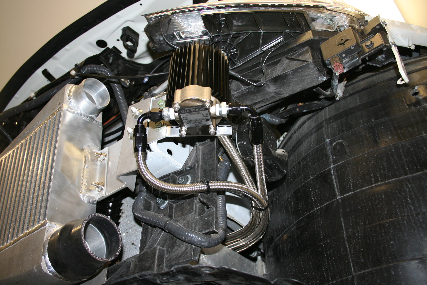
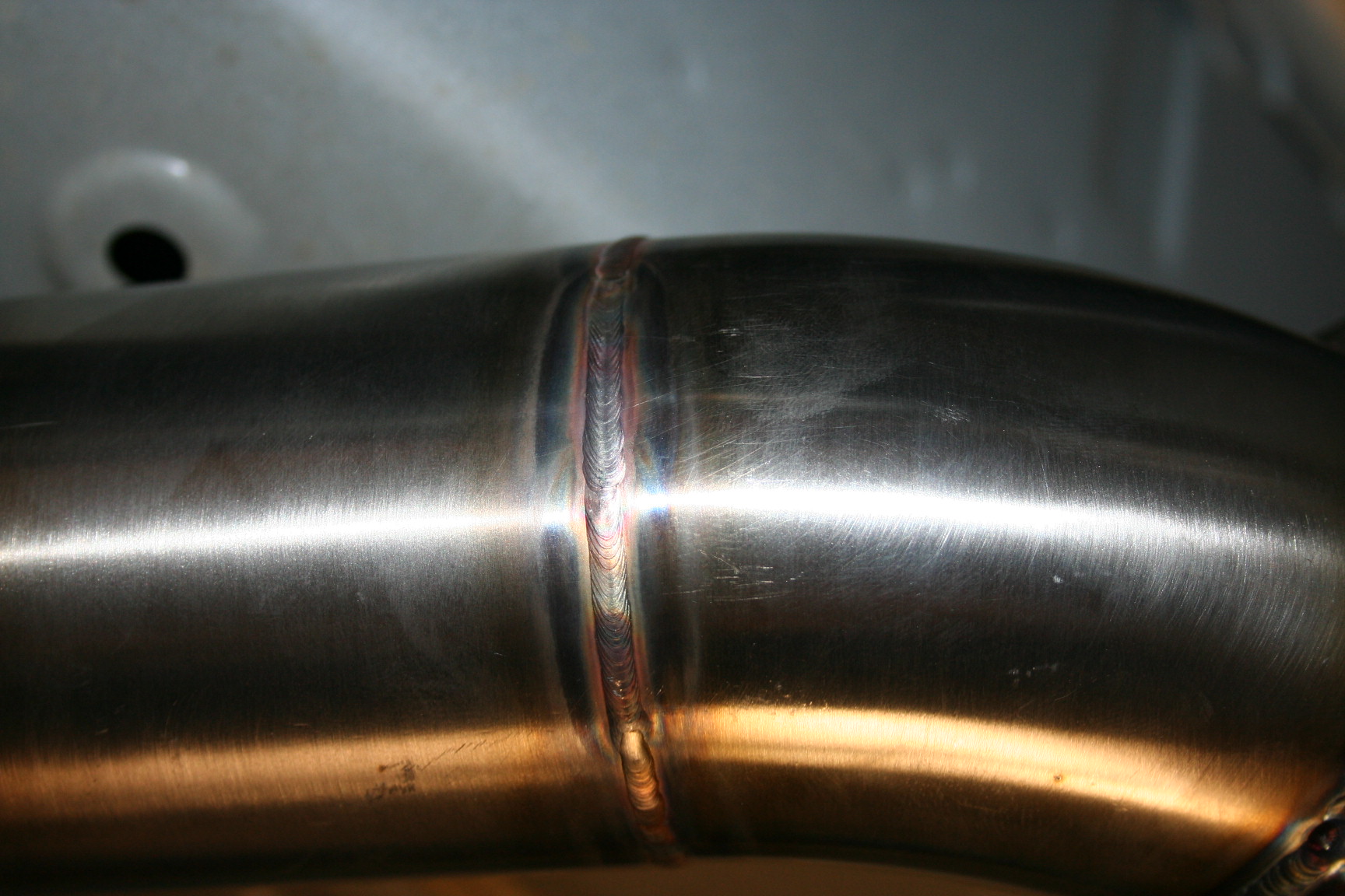
As you can see nothing is left to chance, all of this is top quality, built for performance and durablity.
All the oil stuff is done, oil cooler is installed for good, as is the scavenge pump. Turbo oil fed line is also complete, so the front bumper is close to going back on. I have to do a bit of intercooler pipe work first thing in the morning, so that I have a set of charge pipe (engine bay) to keep with me.
On to the pictures:
Spacer with oil return port:
Getting the OE pan off, you got to use a hammer on this:
Aaaaan off:
RTV on:
Oil cooler with hardware before assembly:
Both FMIC brackets welded solid and bolted on:
Oil pressure sensor with hardware/adapter for turbo oil feed:
Scavenge pump with hardware ready for assembly:
A few oil lines under there:
Final install shot of the pump with all hoses in place, tied up
As you can see nothing is left to chance, all of this is top quality, built for performance and durablity.
Its funny because as many oil lines and fittings etc etc, This is the only kit Ive had on my car that doesn't spit a drop of oil anywhere. Im not sure who to thank Sasha for using quality parts of dynosty for the install.

Thread Starter
Vendor - Former Vendor
iTrader: (14)
Joined: Jan 2010
Posts: 1,782
Likes: 18
From: Edmonton, AB
Last edited by Boosted Performance; Apr 27, 2012 at 07:24 PM.

Thank you.
Turbo and waste gates are the only things under the car. They also sit higher than the aftermarket exhausts I have seen
What you are saying is that you would never put an HKS exhaust (which is more than a turbo and two wastegaes) on your car because you fear ???.
Turbo and waste gates are the only things under the car. They also sit higher than the aftermarket exhausts I have seen
What you are saying is that you would never put an HKS exhaust (which is more than a turbo and two wastegaes) on your car because you fear ???.

That's just me though, I applaud your ingenuity in making these things fit so clean.
Honestly go7, what would happen if the turbo did scrape? Im not sure much of anything. You'd have to bottom out on a daily basis for it to make something bad happen, and I just don't see this happening.
Thread Starter
Vendor - Former Vendor
iTrader: (14)
Joined: Jan 2010
Posts: 1,782
Likes: 18
From: Edmonton, AB
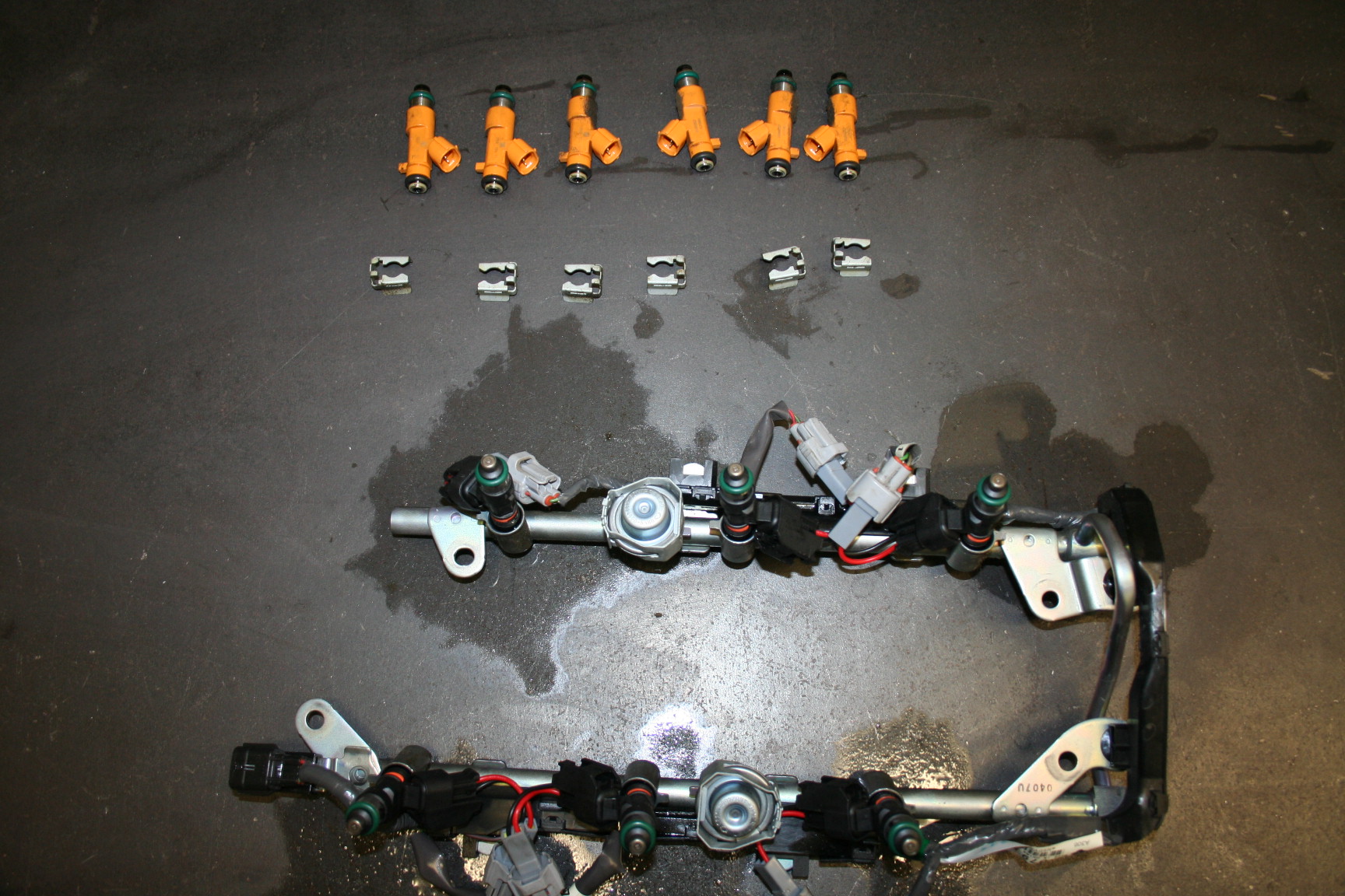
Yesterday was fuel day. Got the OEM plenum off (very easy to do) and removed the fuel rails (also very easy task).
OEM fuel rails/injectors ready for the new 750cc injectors with pigtails:
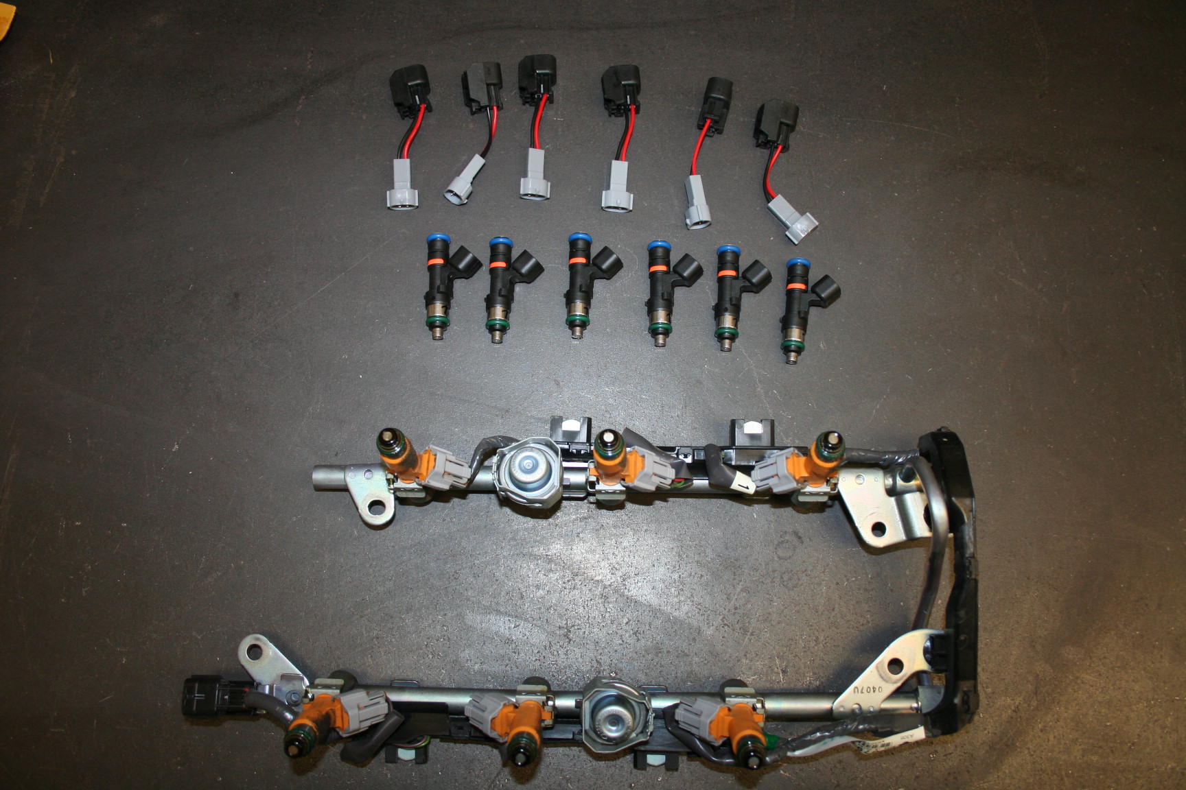
A few minutes later, old injectors out and new ones in:
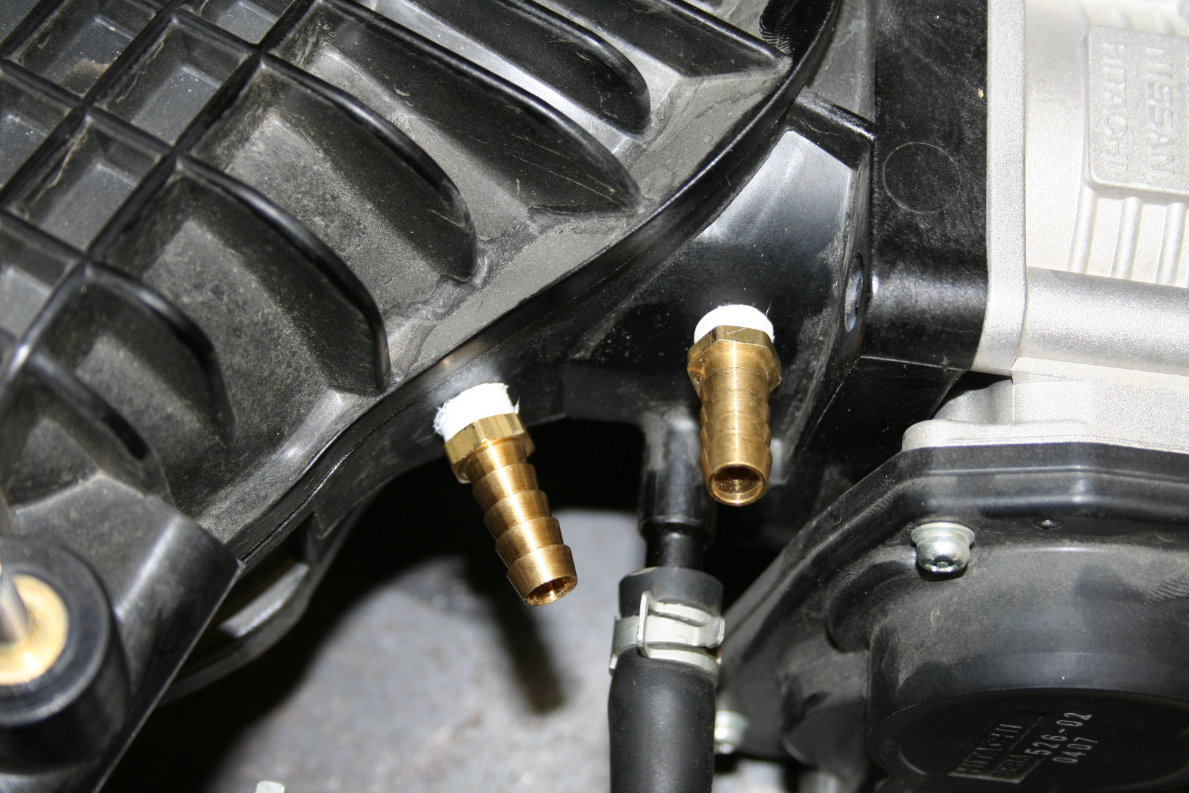
With the plenum off, it was a good time to add two ports to it. One will be for the waste gates, and the other will be used on the BOV's. Removing the TB is a must, because there will be a good amount of plastic on the inside to clean up form drilling/taping. The TB is also very easy to remove, just 4 allen head bolts and it is off.
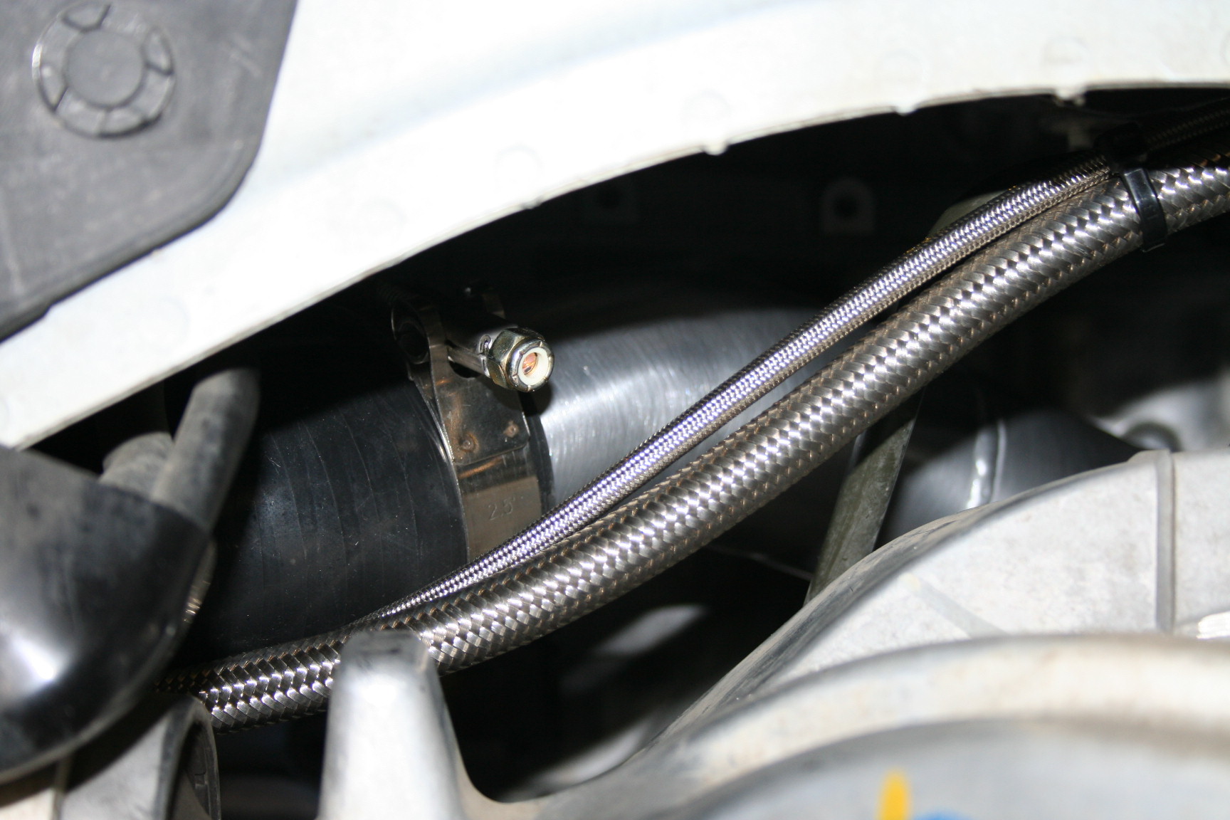
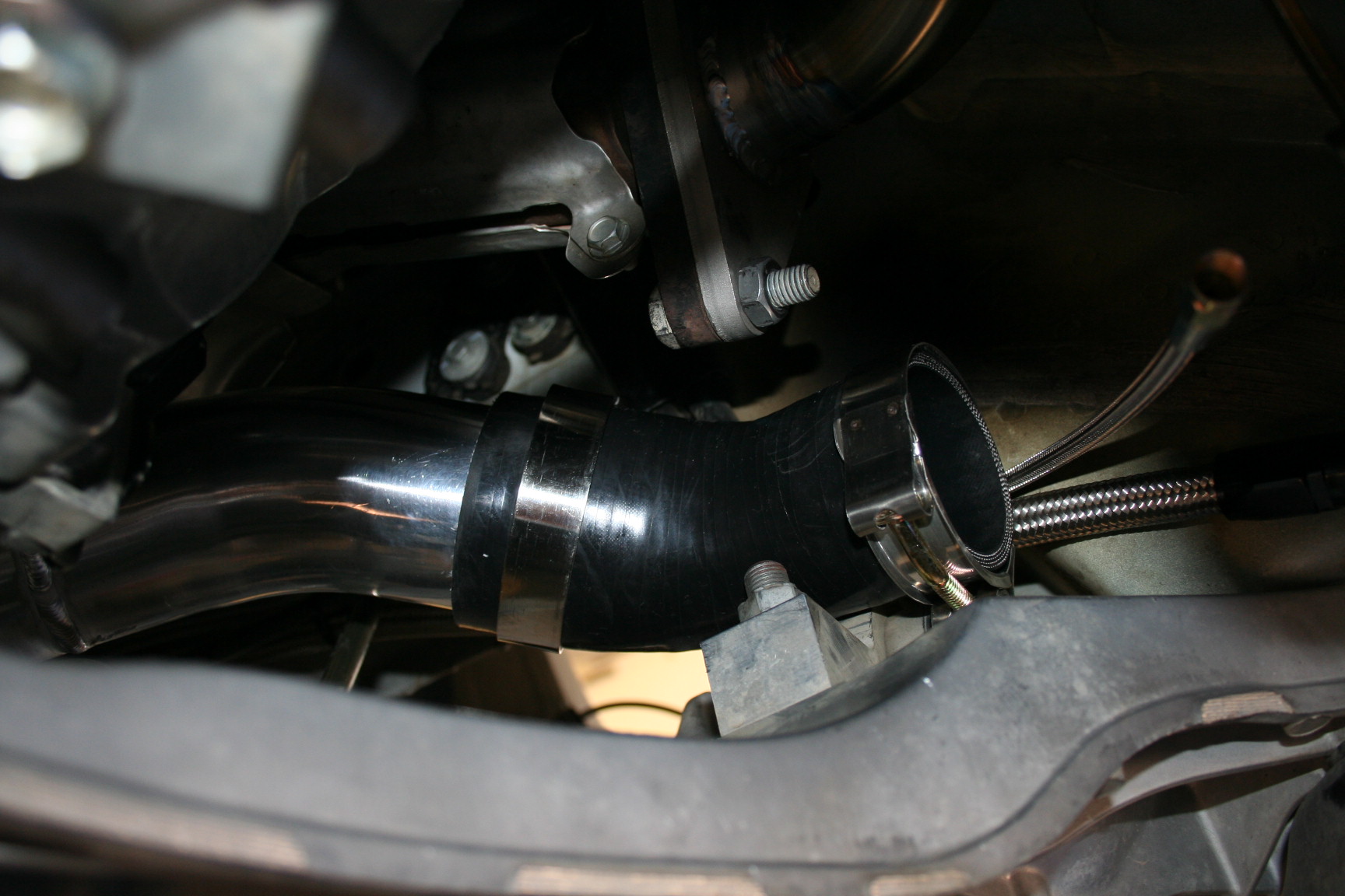
The oil lines to the turbo, viewed from the passenger side wheel well. (wheel removed):
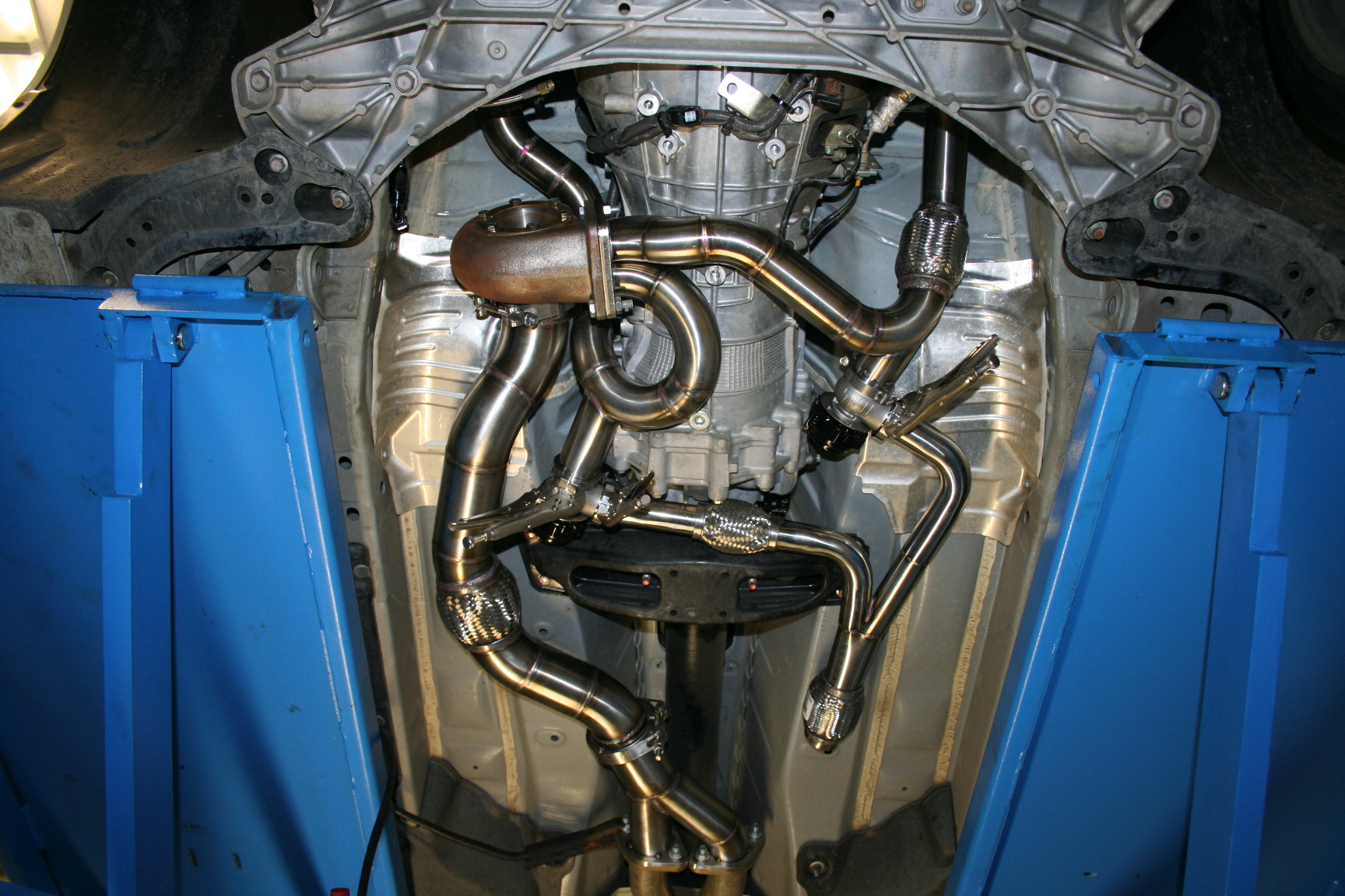
Then it was time to start putting things together for the final time...first pipe going to the turbo:
Then #2 goes in:
Followed by #3, inserted from the other side (header):

Clamps are on, ready for the turbo to go in:
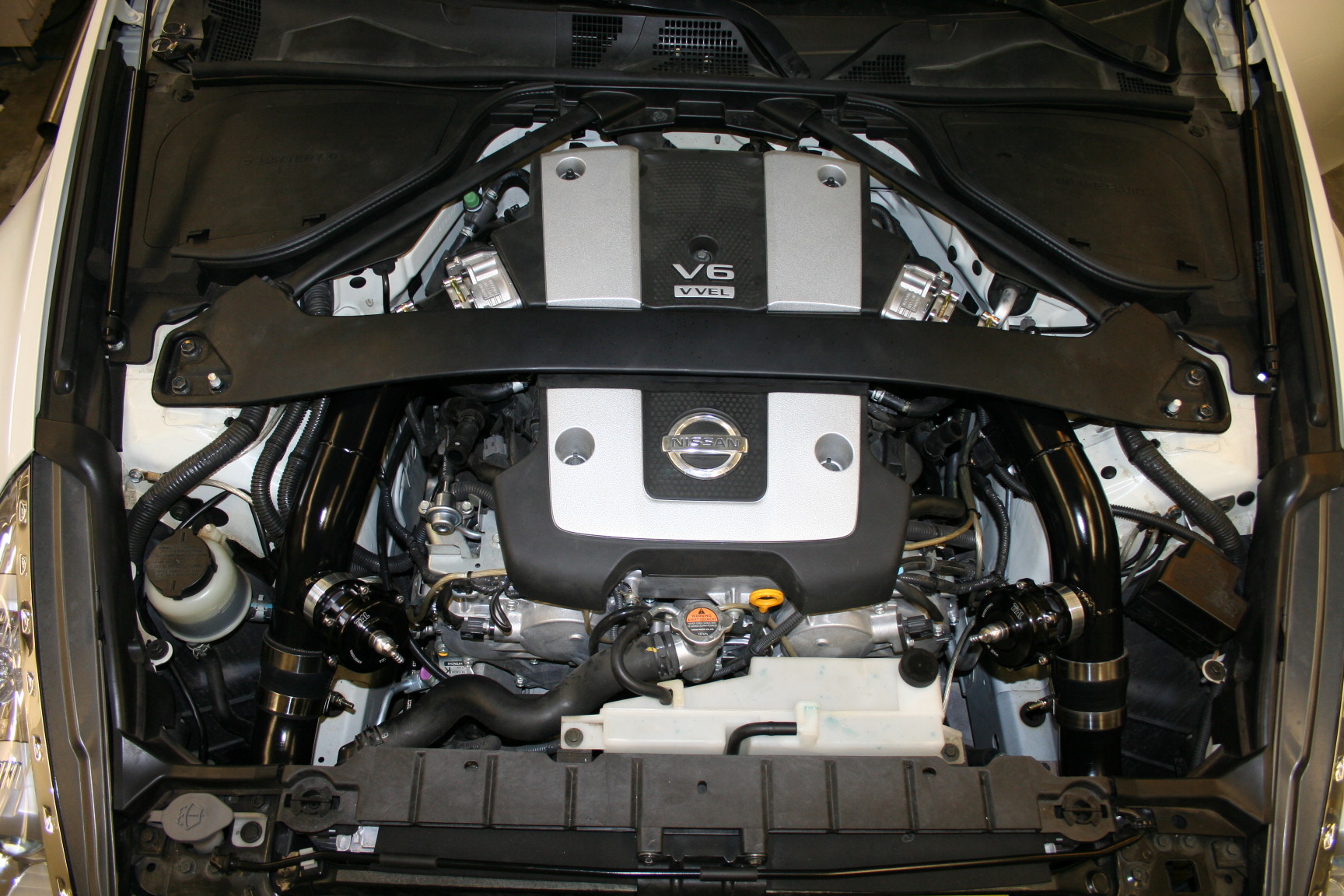
With all the IC piping done under the car, it was time to move up top:
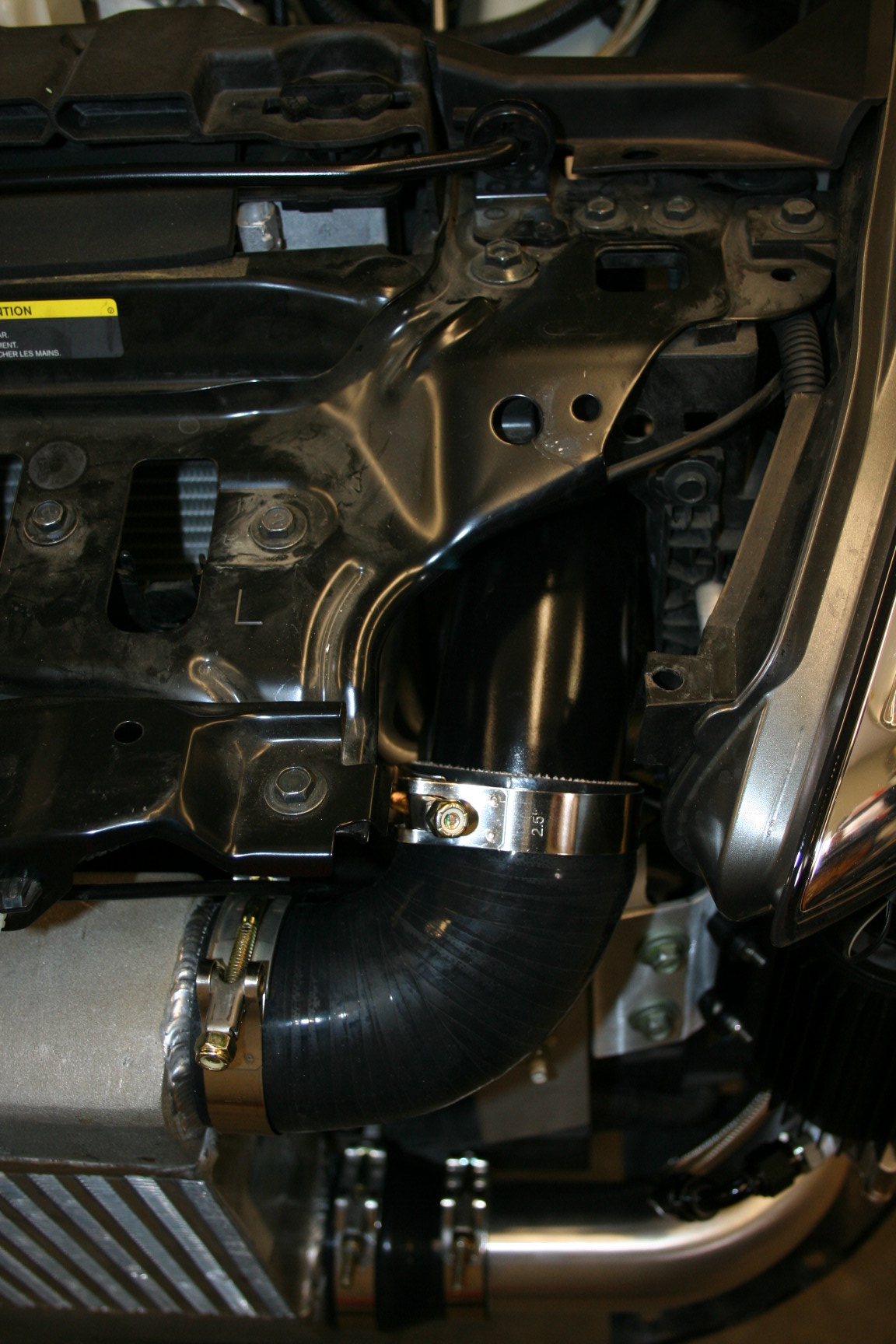
Driver side:
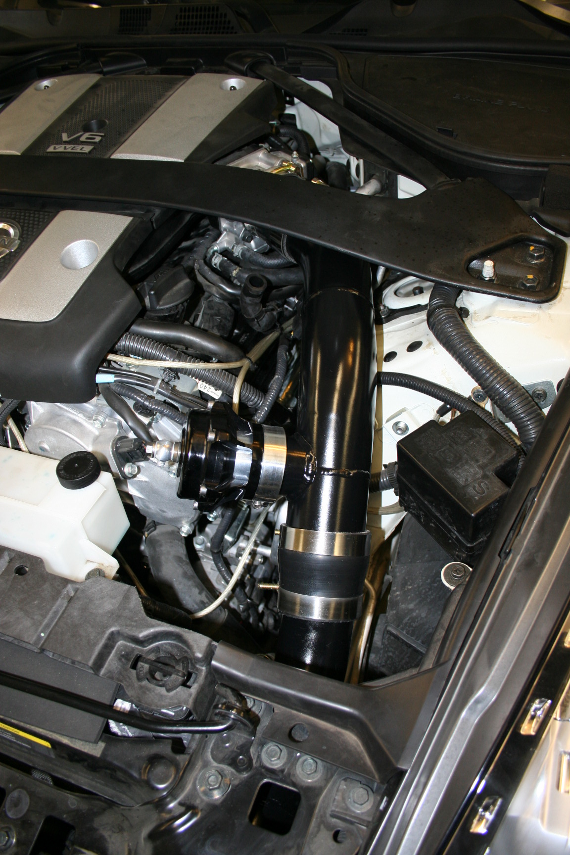
Passenger side:
All done:
Things to do:
-Plug'n play wire harness/relay for the scavenge pump (evening project)
-Fuel pump install (possibly today)
-Waste gate pluming/recirculation (x2 for the kit that stays behind)
-Go over everything and make sure it is good
Hope to get a base map for the 750cc injectors and UpRev soon, and then we start her up.
OEM fuel rails/injectors ready for the new 750cc injectors with pigtails:
A few minutes later, old injectors out and new ones in:
With the plenum off, it was a good time to add two ports to it. One will be for the waste gates, and the other will be used on the BOV's. Removing the TB is a must, because there will be a good amount of plastic on the inside to clean up form drilling/taping. The TB is also very easy to remove, just 4 allen head bolts and it is off.
The oil lines to the turbo, viewed from the passenger side wheel well. (wheel removed):
Then it was time to start putting things together for the final time...first pipe going to the turbo:
Then #2 goes in:
Followed by #3, inserted from the other side (header):
Clamps are on, ready for the turbo to go in:
With all the IC piping done under the car, it was time to move up top:
Driver side:
Passenger side:
All done:
Things to do:
-Plug'n play wire harness/relay for the scavenge pump (evening project)
-Fuel pump install (possibly today)
-Waste gate pluming/recirculation (x2 for the kit that stays behind)
-Go over everything and make sure it is good
Hope to get a base map for the 750cc injectors and UpRev soon, and then we start her up.

Thread Starter
Vendor - Former Vendor
iTrader: (14)
Joined: Jan 2010
Posts: 1,782
Likes: 18
From: Edmonton, AB
Well, it's 1:15AM and I am done for yesterday I guess.
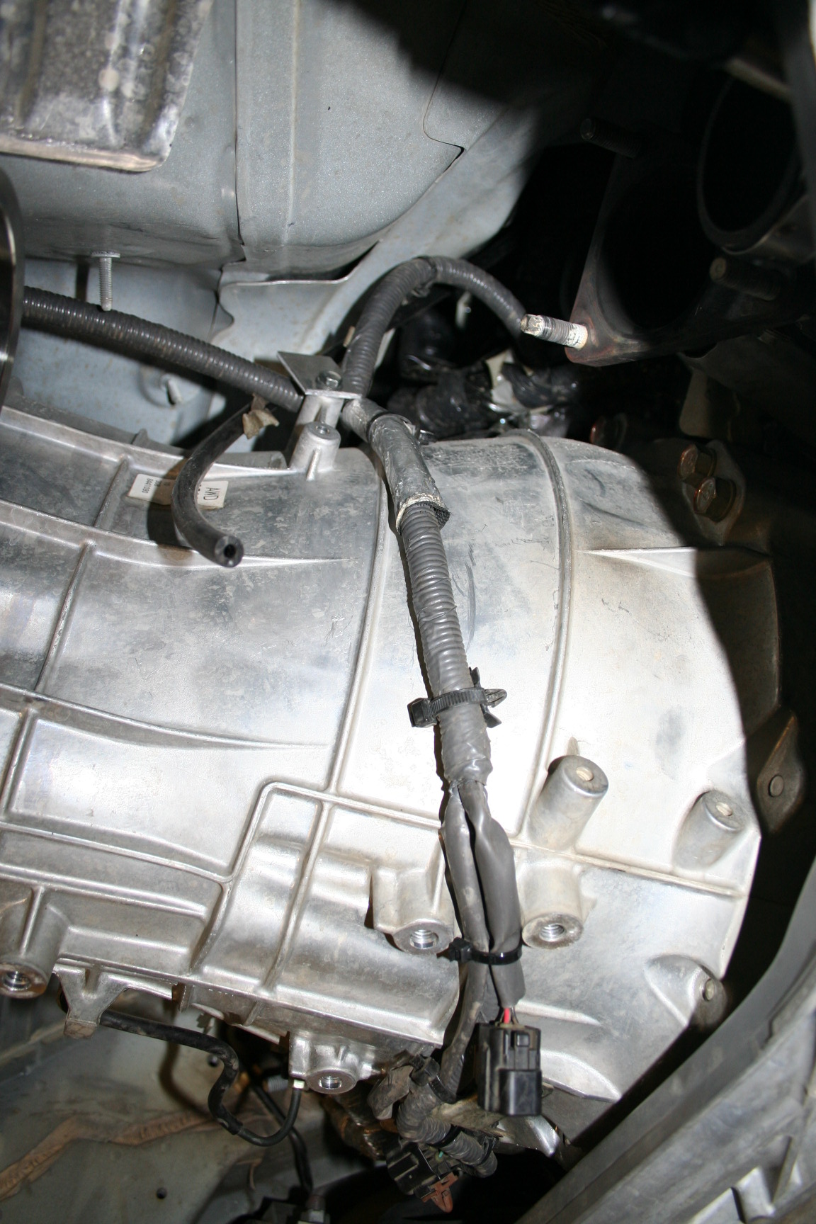
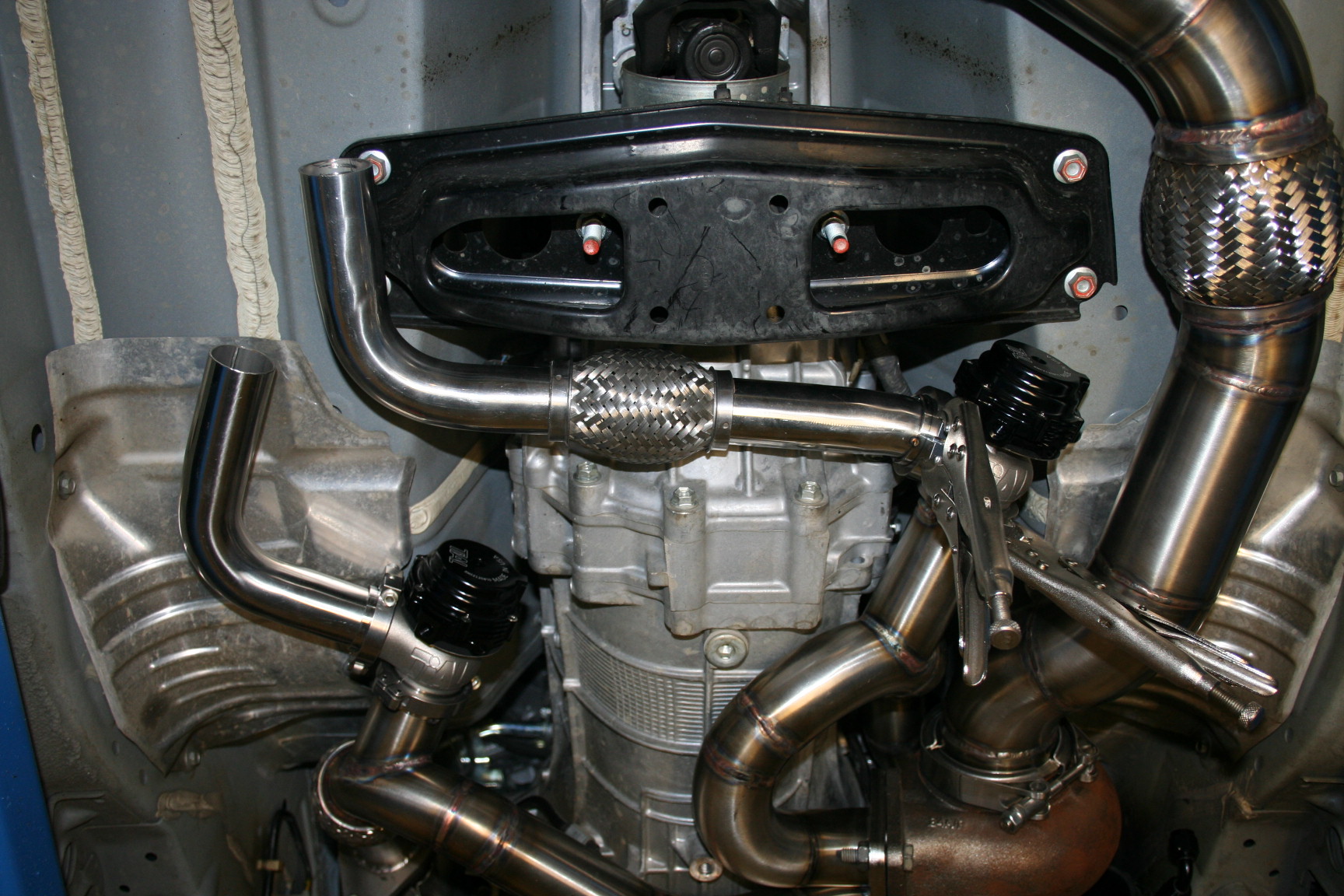
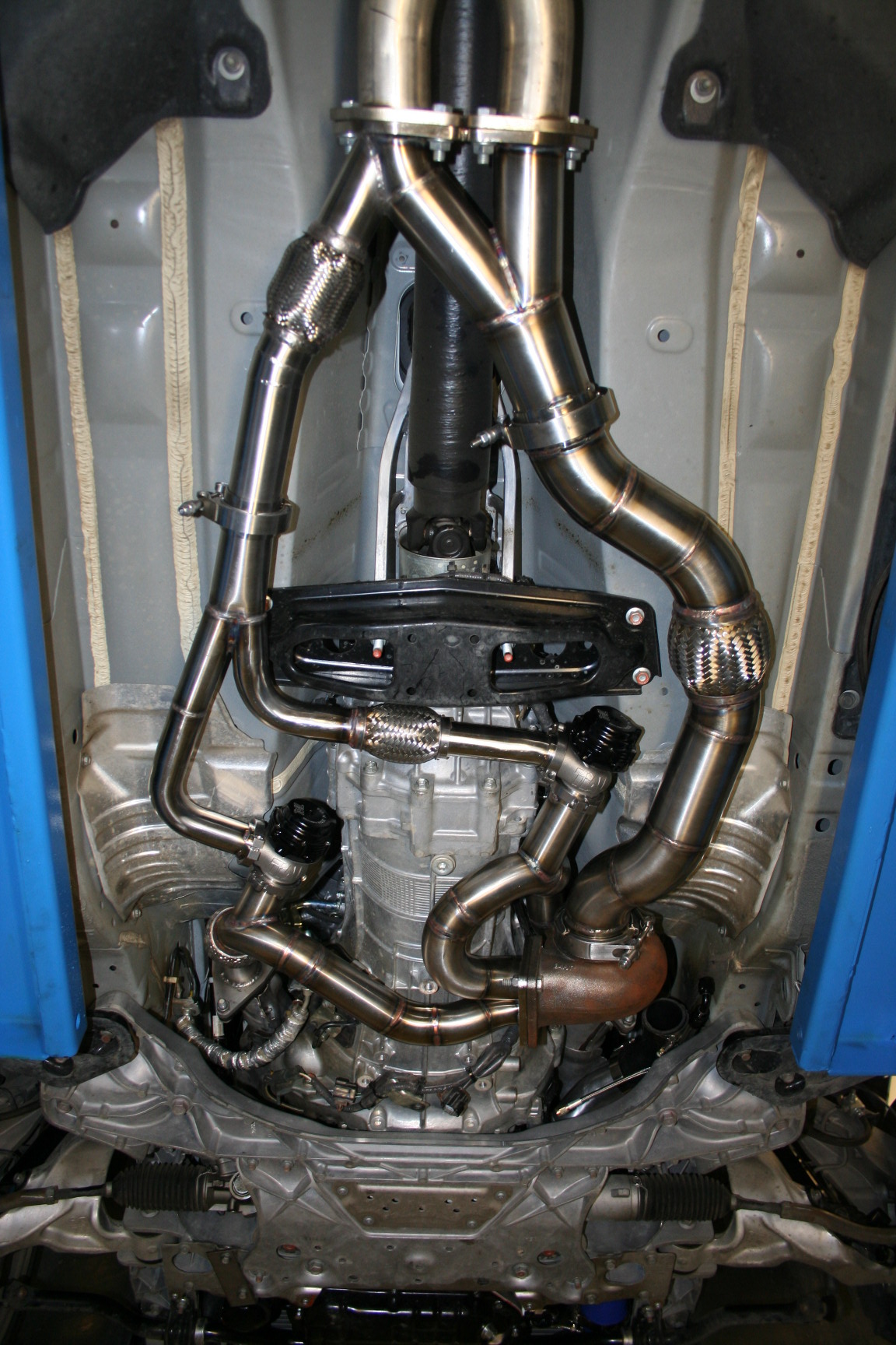
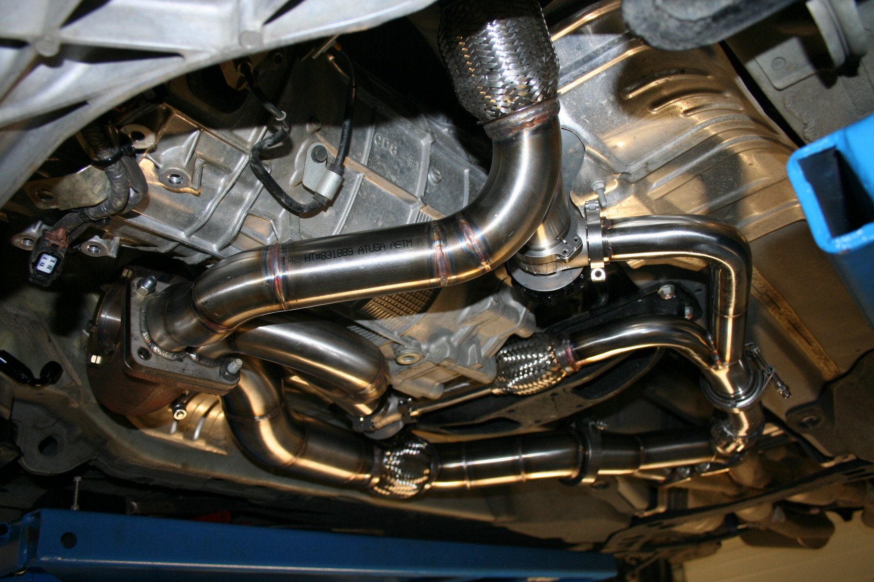
Got a solid start on the wastegates. While at it I had to move the transmission harness further up..no big deal at all, takes about two minutes. This is where the passenger side exhaust pipe runs.
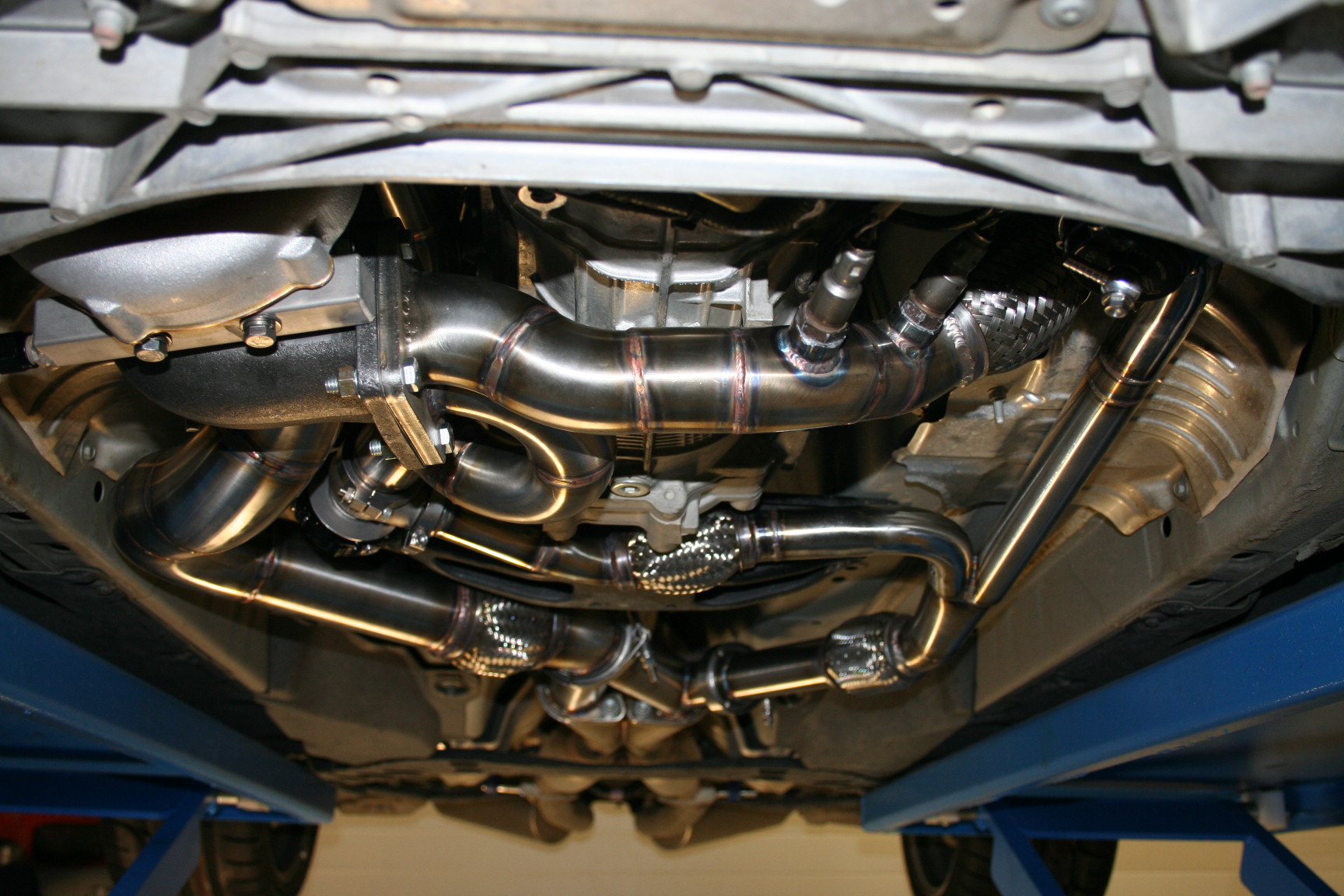
Up and away:
Then I moved on to welding the waste gate pipes on:
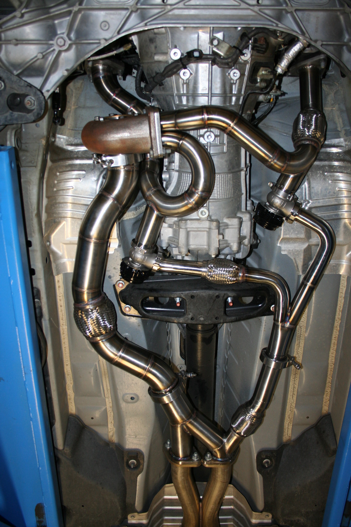
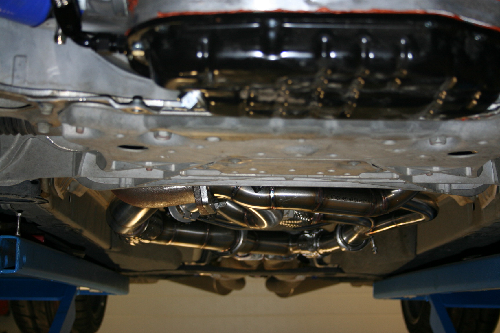
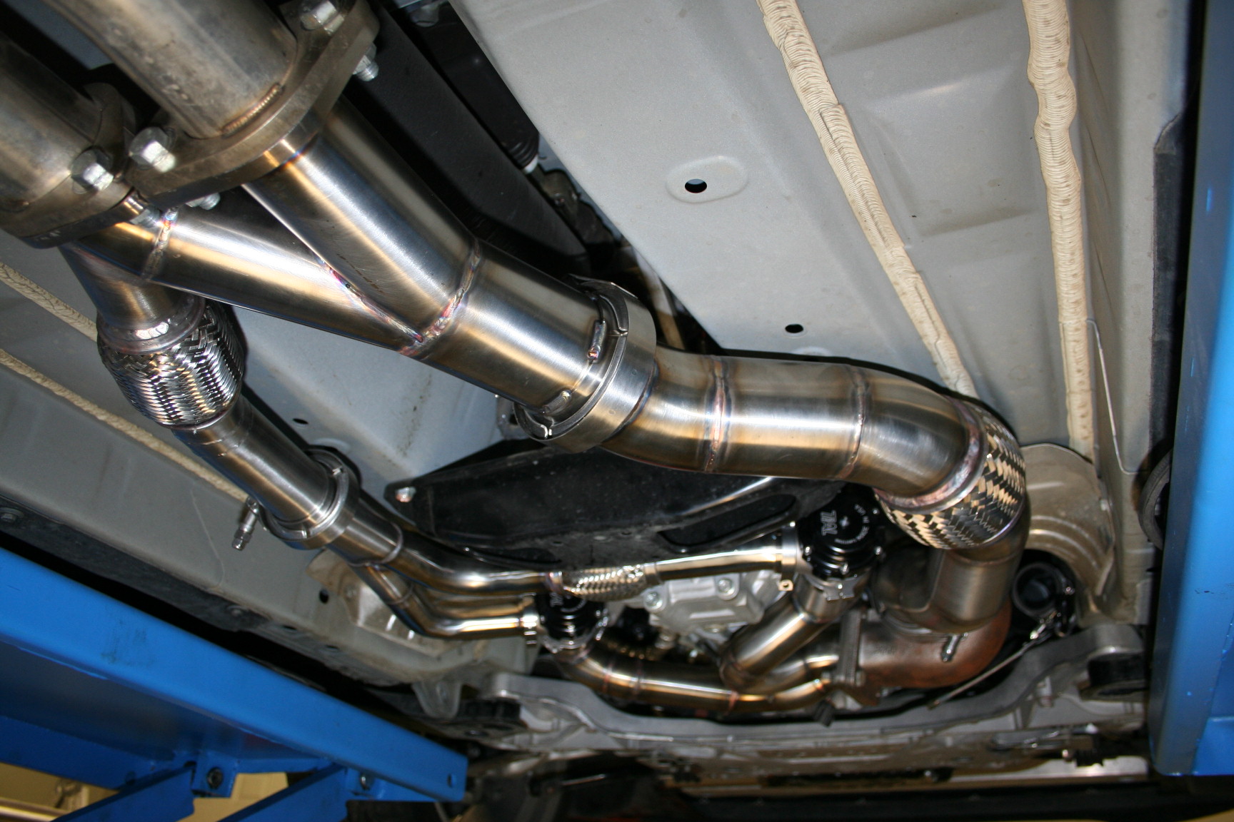
Looking good installed:
They are up and away from everything:
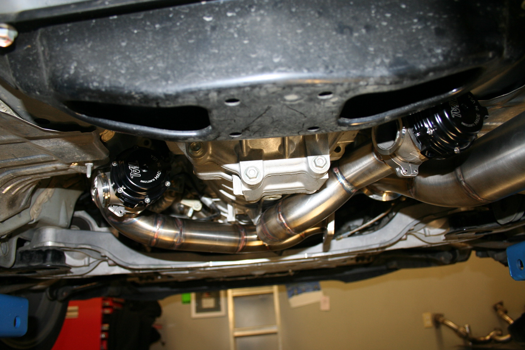
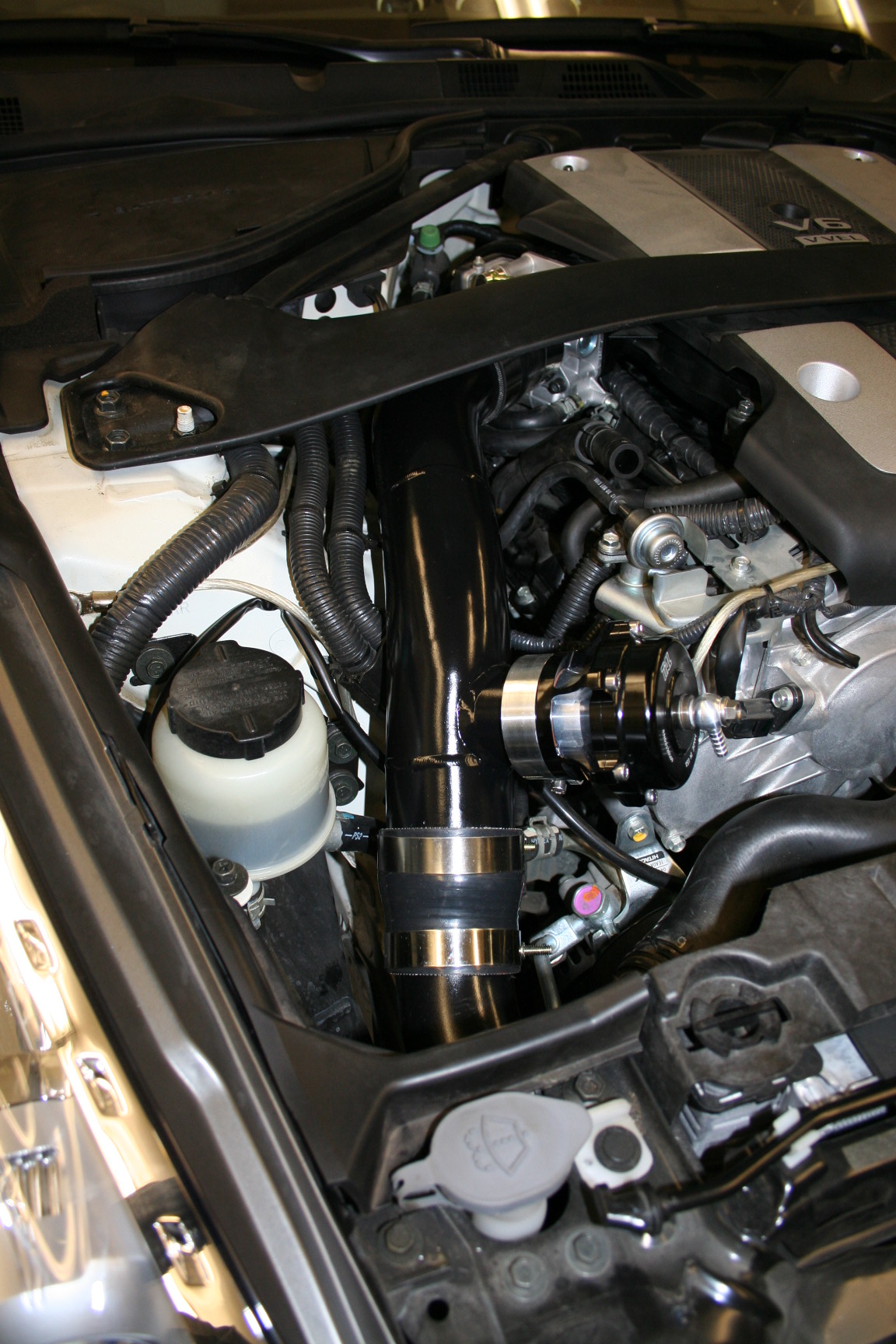
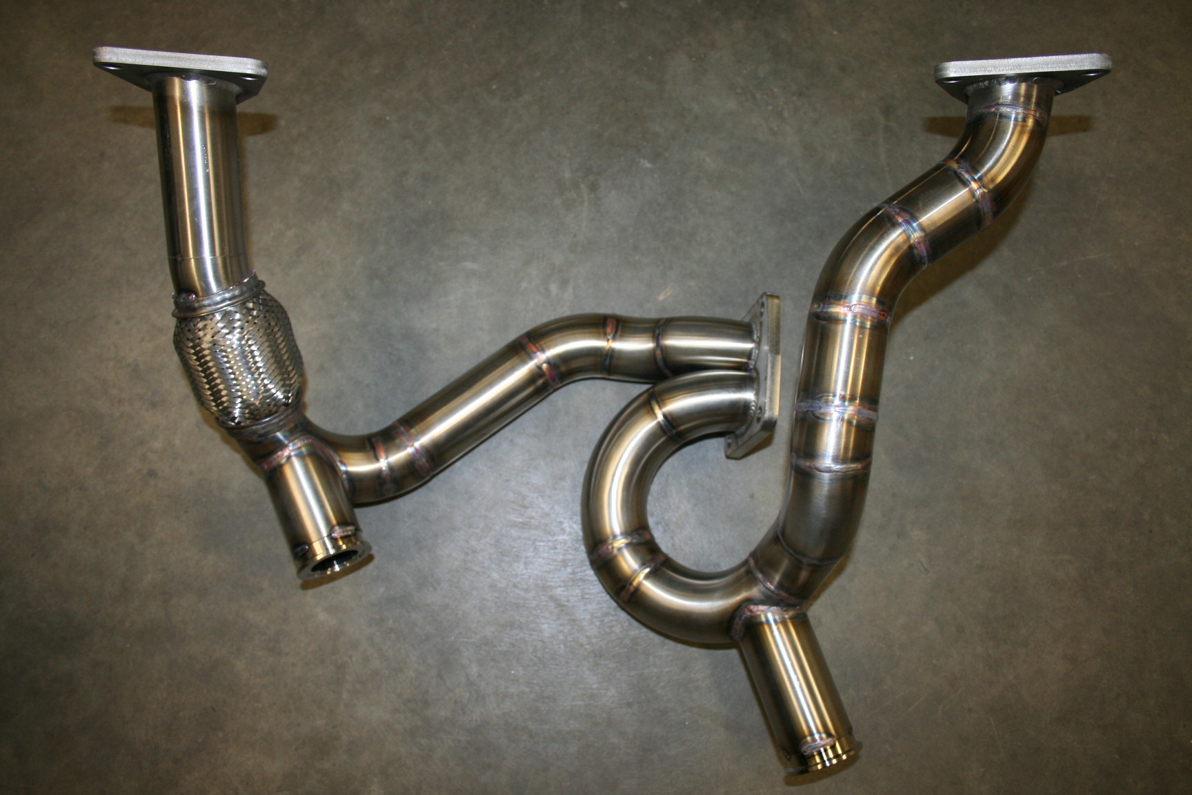
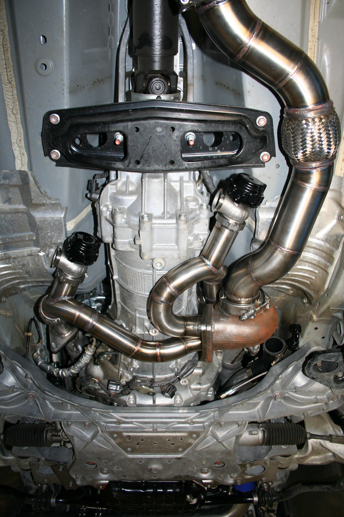
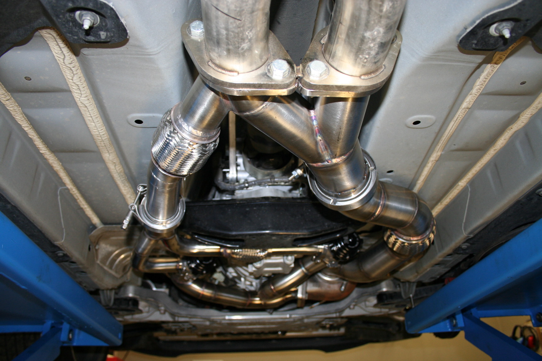
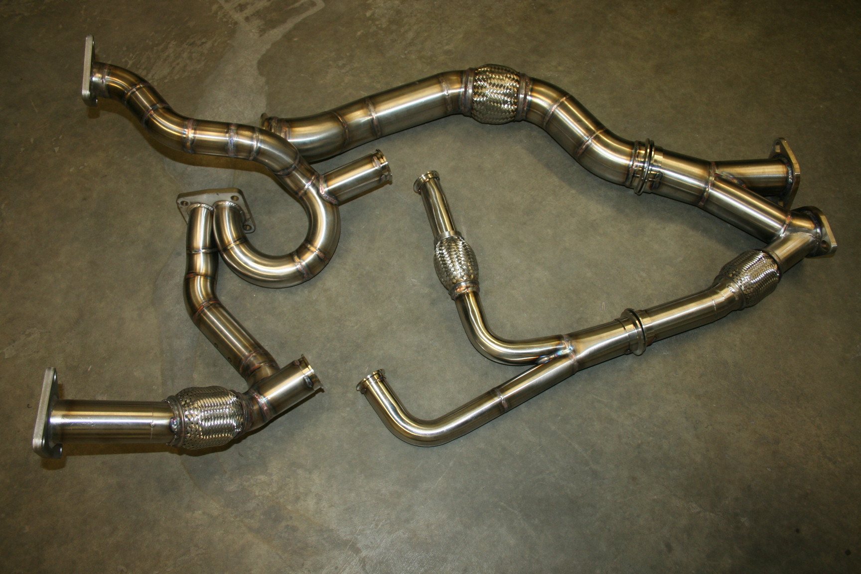
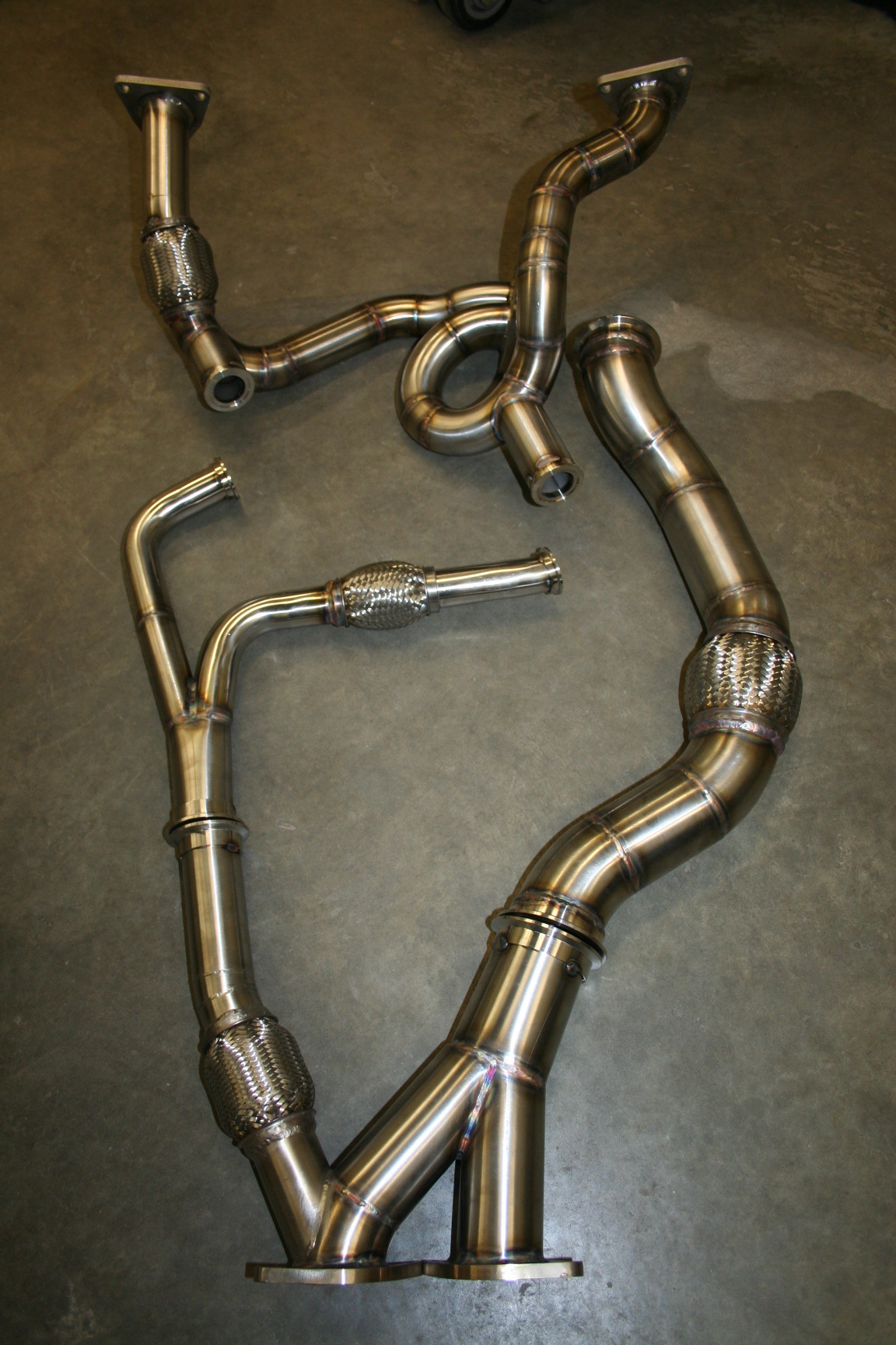
Then I started the hard part, merging the two together. Each waste gate has a 1.5" outlet, and after merging it goes up to a single 2" pipe. It will go in to the driver side of the Y-pipe that goes in to the F.I exhaust:
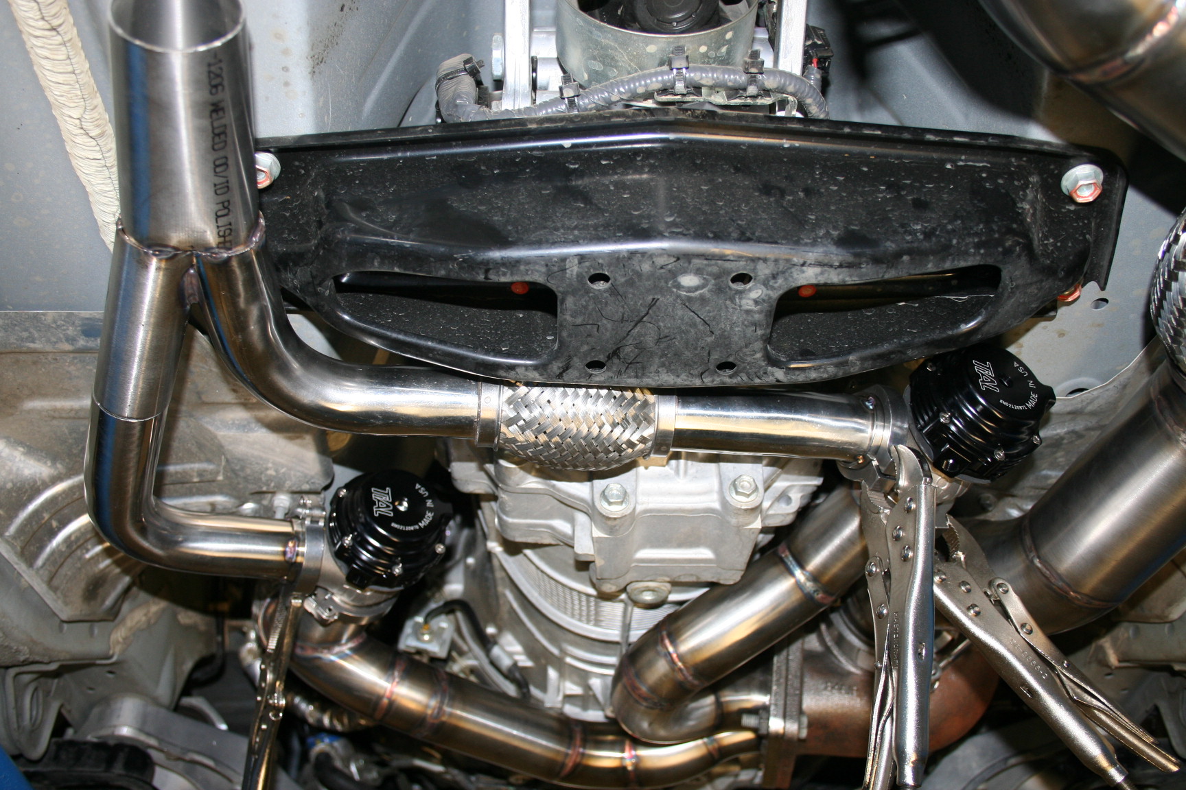
As it sits now:
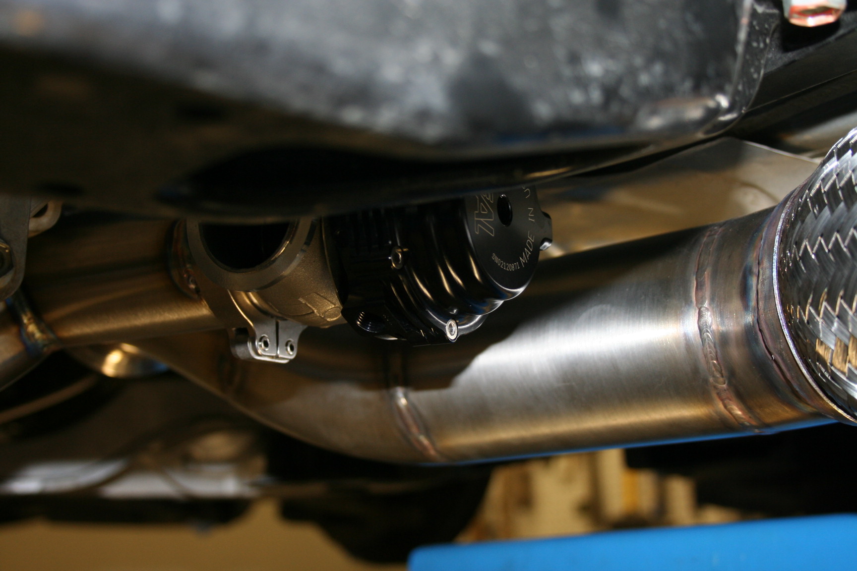
There will be a 2" V-band flange after that flex coupler that goes nowhere, and then another short section which will merge with the rest of the exhaust. This is something that I will do later on today I guess.
In case anybody is wondering about all the flex pipes. They serve two purposes. The install is made easier as there is a bit of give in them. The other (even more important purpose) is to keep things flexible during heat cycles. If everything was ridged, things would start to crack due to stress. I guess you can compare it to a bridge, if it was solid anchored to both sides it would fall apart rather quick.
I also had a look at how one would get to the fuel pump. It looks like it is behind the back seat, and a bunch of plastic has to be removed to gain access?
Got a solid start on the wastegates. While at it I had to move the transmission harness further up..no big deal at all, takes about two minutes. This is where the passenger side exhaust pipe runs.
Up and away:
Then I moved on to welding the waste gate pipes on:
Looking good installed:
They are up and away from everything:
Then I started the hard part, merging the two together. Each waste gate has a 1.5" outlet, and after merging it goes up to a single 2" pipe. It will go in to the driver side of the Y-pipe that goes in to the F.I exhaust:
As it sits now:
There will be a 2" V-band flange after that flex coupler that goes nowhere, and then another short section which will merge with the rest of the exhaust. This is something that I will do later on today I guess.
In case anybody is wondering about all the flex pipes. They serve two purposes. The install is made easier as there is a bit of give in them. The other (even more important purpose) is to keep things flexible during heat cycles. If everything was ridged, things would start to crack due to stress. I guess you can compare it to a bridge, if it was solid anchored to both sides it would fall apart rather quick.
I also had a look at how one would get to the fuel pump. It looks like it is behind the back seat, and a bunch of plastic has to be removed to gain access?

Thread Starter
Vendor - Former Vendor
iTrader: (14)
Joined: Jan 2010
Posts: 1,782
Likes: 18
From: Edmonton, AB
The car is now ready to go, just need the base map for the 750cc injectors (should be in today).
This is what things look like before the car is back on the ground;
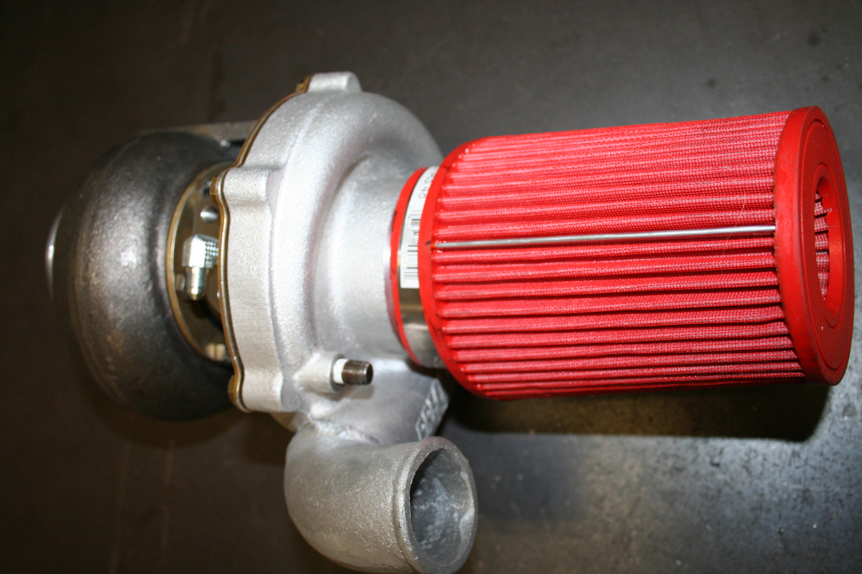
Turbo with filter before install:
Up there:
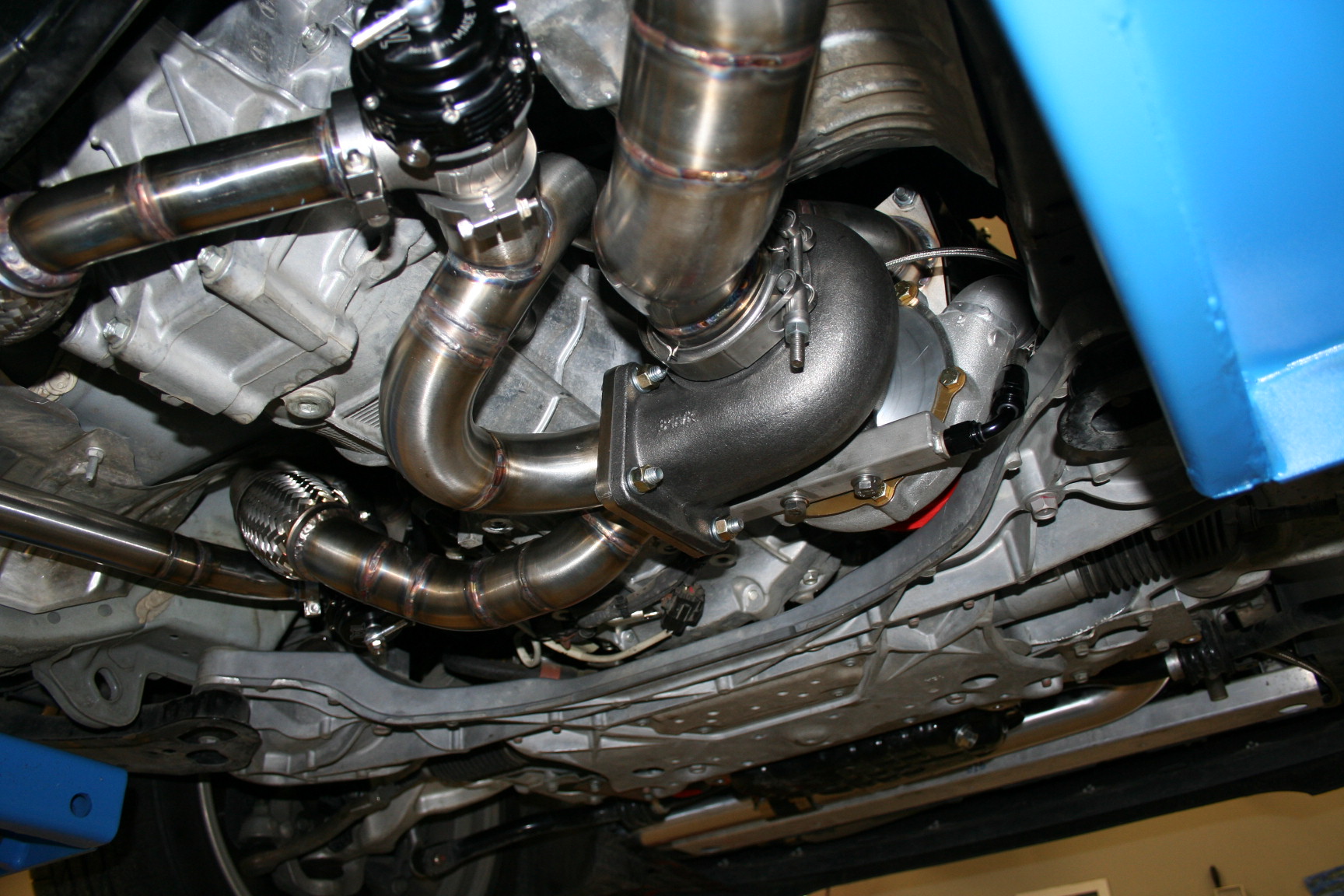
O2 Sensors are in:
I use an oil reservoir on the turbo drain, this is a stainless 1" square tube sleeved so it can never leak. This allows the oil inside the turbo to drain, so it does not leak past the seals while the car is off, in turn, it will never smoke.
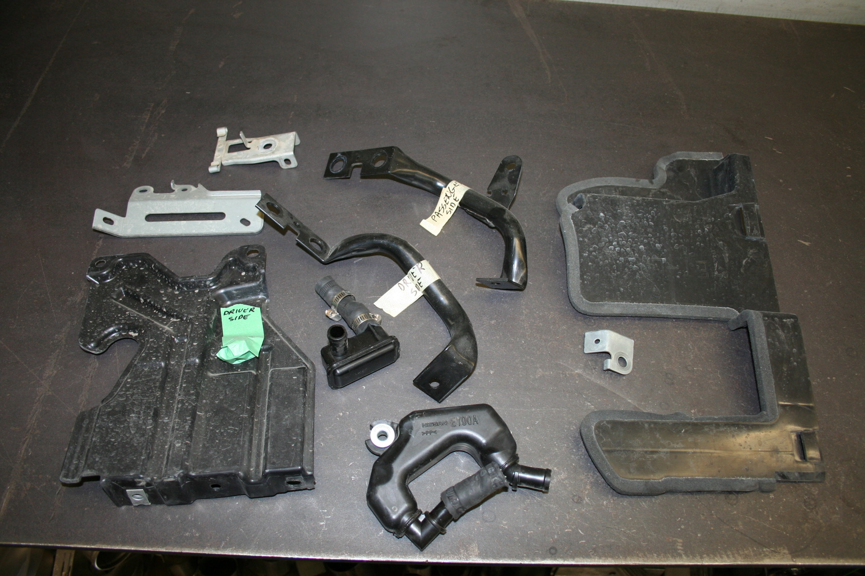
These are the only things that did not go back on the car, aside from the crash bar:
This is what things look like before the car is back on the ground;
Turbo with filter before install:
Up there:
O2 Sensors are in:
I use an oil reservoir on the turbo drain, this is a stainless 1" square tube sleeved so it can never leak. This allows the oil inside the turbo to drain, so it does not leak past the seals while the car is off, in turn, it will never smoke.
These are the only things that did not go back on the car, aside from the crash bar:
Thread Starter
Vendor - Former Vendor
iTrader: (14)
Joined: Jan 2010
Posts: 1,782
Likes: 18
From: Edmonton, AB
2.0 on that run. I made a thread in the drag forums, just wanted to come litter your thread a bit and get OT. I am having serious traction problem and need a driving lesson from Hal apparently on drag racing.
Thread Starter
Vendor - Former Vendor
iTrader: (14)
Joined: Jan 2010
Posts: 1,782
Likes: 18
From: Edmonton, AB
UPDATE:
James (customer/owner) came by last night and got the car out on the road. After a short drive everything seemd good, even the base map was very good. He parked the car for 30 minutes, and came back to start it up and go for another quick spin. Shortly after strarting he noticed smoke out the back (exhaust)....after a couple of texts we agreed that it was best to come back this morning for me to go over everything...ensuring him that it is not a big deal....(don't think he bought any of it though :lol
I got the car on the lift, and noticed a bit of oil resedue coming out of the turbine housing...both sides. I made sure that the pump was working, and dwawing good vaccum, so that was not the issue. This confirmed that the turbo seals could not have possibly blown, and everythig else looked very good.
When I installed the oil feed line, I did not install a check valve at the turbo oil inlet as I do with the 350z kits. Reason behind that is that the oil line feeding the turbo with this kit is very short, and even if it was to completely drain, it was not going to be enough oil to fill the small reservoir I use at the turbo drain. I was wrong...it seems that there is still pressure left in the system after shut down, and that the path of least resistance is taken by the oil to relieve this pressure. It turns out that the path of least resistance is the turbo. So after he shut the car down, the oil reservoir filled up, as did the turbo. With the oil sitting in the center section some leaked past the seals and in to the turbine housing/exhaust. When he went to run the car, this oil started to burn up causing the smoke. No harm done...just a bit of oil going past the turbo seals.
I installed a check valve this morning, and we went out for a spin....all is perfect. No smoke (after it all burnt up from yesterdays leak) and the car pulls great, sounds amazing, and sure puts a smile on the drivers face. We did a few WOT pulls so the logs can be sent out for analysis, and we shall go on from there. I must admit that the turbo combo with the F.I exhaust is just perfect, quieter than on a stock block, making this car the perfect sleeper.
The car will get some miles on it now, and come back for another visual inspection. If all is good, this was a complete success, and I will proceed with making the jigs for this kit. This will take a bit of time as the jigs will be complex, and take time to build just right.
I would really like to thank Vince at R/T tuning for coming through with the base map...I can't believe how good it is considering he has never seen this kit. I would highly recommend him and his services to anybody. He really is the UpRev guru.