
Motorized nav cubby solution


Hello everyone,
I just finished building a controller for the motorized navigation door. It uses open source hardware to interface with the door module's circuit board and control the door using nothing but a 12v power source.
I used a standard Arduino Duemilanove connected to a L298N shield similar to this one and connected it to the motor circuit board on the nav door unit:
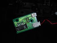
This board is part of the navigation motor assembly. It has wires that connect the button on the lid and the motor itself, and more importantly the limit switch used to tell the controller when to stop the motor.
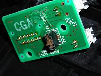
This is the limit switch on the bottom of the board.
The Arduino has a ton of inputs so it was easy to give each button on the board its own connection to the Arduino and do all the hard work with software instead of electronics.
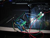
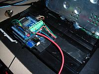
This is the prototype of the wiring. There are two positions on the limit switch, one for up and one for down; each has its own connection to an input on the arduino. The button on the lid also has a connection. The motor on the lid is connected directly to the L298N motor shield on the Arduino. The motor sheild can drive the motor directly and only needs software to tell it what to do. The other wires are the 12v power supply.
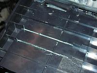
The only modification is to trim some of the ribs on the bottom of the navigation housing to allow for a flat mounting spot for the arduino. I chose to attach it with strong double sided tape, screws weren't an option due to clearance with the drive mechanism. I also drilled some small holes to pass the wires through to the controller board on the other side of the housing.
And here is the whole assembly cleaned up and mounted on the navigation unit. The hot glue is to keep all the wires where they're supposed to be and out of the moving parts and other components in the vehicle.
And finally I have a youtube video showing the finished project in action:
Watch it in action on youtube
The whole process was pretty simple and cheap. I spent about $45 on the Arduino hardware and maybe 3 hours assembling everything including the time to write the software for the controller.
Just thought I'd share for anyone else out there who wants to use a motorized door but not the crappy factory nav system.
I just finished building a controller for the motorized navigation door. It uses open source hardware to interface with the door module's circuit board and control the door using nothing but a 12v power source.
I used a standard Arduino Duemilanove connected to a L298N shield similar to this one and connected it to the motor circuit board on the nav door unit:

This board is part of the navigation motor assembly. It has wires that connect the button on the lid and the motor itself, and more importantly the limit switch used to tell the controller when to stop the motor.

This is the limit switch on the bottom of the board.
The Arduino has a ton of inputs so it was easy to give each button on the board its own connection to the Arduino and do all the hard work with software instead of electronics.

This is the prototype of the wiring. There are two positions on the limit switch, one for up and one for down; each has its own connection to an input on the arduino. The button on the lid also has a connection. The motor on the lid is connected directly to the L298N motor shield on the Arduino. The motor sheild can drive the motor directly and only needs software to tell it what to do. The other wires are the 12v power supply.

The only modification is to trim some of the ribs on the bottom of the navigation housing to allow for a flat mounting spot for the arduino. I chose to attach it with strong double sided tape, screws weren't an option due to clearance with the drive mechanism. I also drilled some small holes to pass the wires through to the controller board on the other side of the housing.

And here is the whole assembly cleaned up and mounted on the navigation unit. The hot glue is to keep all the wires where they're supposed to be and out of the moving parts and other components in the vehicle.
And finally I have a youtube video showing the finished project in action:
Watch it in action on youtube
The whole process was pretty simple and cheap. I spent about $45 on the Arduino hardware and maybe 3 hours assembling everything including the time to write the software for the controller.
Just thought I'd share for anyone else out there who wants to use a motorized door but not the crappy factory nav system.


Trending Topics
Yes, this is to use the motorized door unit with an after market navigation system or video display. I have a 7" USB LCD in the housing connected to my car pc so I can use it for whatever I want.


Registered User
Joined: Oct 2009
Posts: 4
Likes: 0
From: England
Hey MDK, I'm dong the exact same thing you did with the NAV door. I already have the arduino board and motor shield and wires. I was reading your post as a guide to completing mine but had a couple questions with the wiring. What wire do you wire to what exactly? How did you take that black connector off? The pictures only help so much. What capacitors did you use in conjuction, and in which wires exactly? Basically, if you can give me a breakdown of exactly how you wired every wire and where you soldered what wire, that would be of tremendous help. Or if it is easier for you just to tell me by phone, please let me know and I can give you a call. The thing is, I'm in the military stationed in England and so I wouldn't want you to incure ridiculous phone charges. Thanks


Registered User
Joined: Feb 2015
Posts: 2
Likes: 0
From: Bloomington il
Your smart, but also very stupid! Read a wiring diagram. Seems like a lot of work when you could just buy the nav lid amplifier, get the male connector from the dealer and wire it like to factor did, which I have done about 10 times .


I like his solution since it is highly customizable. Factory will be restricted (like an Apple product) you get what you get.
With the arduino you could program the cubby to open and close with the door locks or ignition ect.
Cool project OP!
My OEM Unit has this built in, it opens when i turn the car on closes when i turn it off, or by pressing the button. So far I've had to replace the circuit board once, and at 120 for the board, I am interested in pricing....
Yeah like Cux said, I did it for flexibility. I'm using a PC in my car instead of a normal head unit, so I can use the Arduino to do all sorts of things like add extra buttons and switches to the car which can do various things on the PC. If you were using a normal head unit this would be overkill and another solution might make sense. That being said, I think I only have about $50-60 in the project.
Long term its held up okay, although I think I'm going to try to figure out some sort of a ribbon cable for the connection to the motor to improve it a bit, the individual wires dont roll back nicely and it makes the open and close action jerky. I ended up fabricating a mount out of metal so that everything is screwed down nice and tight, no more hot glue.
Long term its held up okay, although I think I'm going to try to figure out some sort of a ribbon cable for the connection to the motor to improve it a bit, the individual wires dont roll back nicely and it makes the open and close action jerky. I ended up fabricating a mount out of metal so that everything is screwed down nice and tight, no more hot glue.

Registered User
Joined: Aug 2014
Posts: 2
Likes: 0
From: New jersey
I just got my Z last summer and didn't even realize the cubby was motorized until I took the console apart. so I have 2 questions
1) is it an easy fix to get the motor working again?
2) planning on taking out the factory nav. will that affect the motorization?
sorry if these questions have been answered before
thanks
1) is it an easy fix to get the motor working again?
2) planning on taking out the factory nav. will that affect the motorization?
sorry if these questions have been answered before
thanks

Thread
Thread Starter
Forum
Replies
Last Post
Colombo
Forced Induction
35
Nov 9, 2020 10:27 AM
ars88
Zs & Gs For Sale
18
Apr 4, 2016 07:52 AM