
Footwell Lighting How-To,


At the request of many of you guys, I've put together a how to do the footwell lighting as best I can. Keep in mind I've already done the install without taking the pictures first so I went back to take pictures just now to do the writeup, so my wiring has already been done, and some steps I chose not to go through the trouble of taking things apart again.
I have to give some credit to Acree from his LED Door handles thread here:
https://my350z.com/forum/body-interior-exterior-and-lighting-diy/206837-diy-led-door-handles-full-walk-through.html
He basically gave me enough information to be able to wire the lighting from the dome lights.
Necessary materials:
Lighting method
18 gauge wiring
Splicing tool
Electrical tape/Soldering Iron
Large Flathead
Zip Ties/Double sided tape/Whatever necessary to mount.
10mm ratchet to disconnect battery.
First off is to get a hold of what you want to light the footwell. Neons, cathodes, what have you, as long as its powered by 12V then your good to go with wiring things up without resistors.
I chose cathodes because I already had some white ones that were bright and looked great. Got them here:
http://www.svc.com/clk12wt2.html
You will need 2 of these. You will see why.
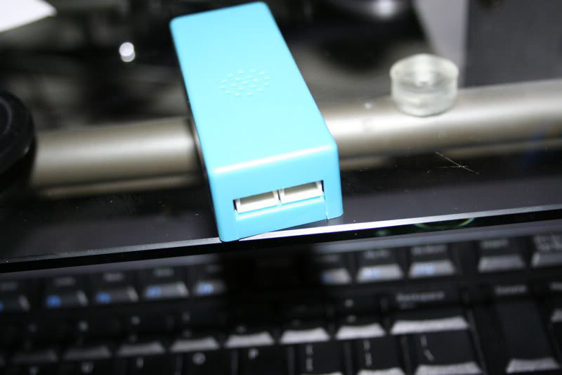
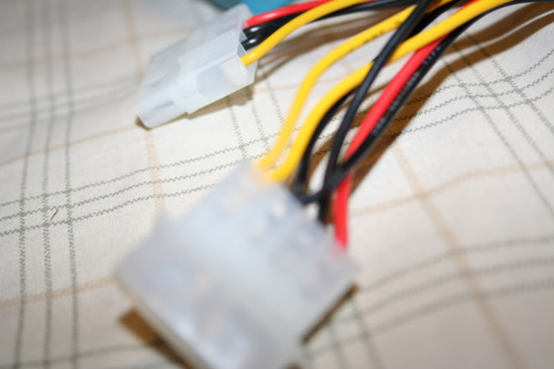
Now when the kit is in front of you, take out the blue inverter (the blue plastic box), it has two ends:
This is for the wire harness:
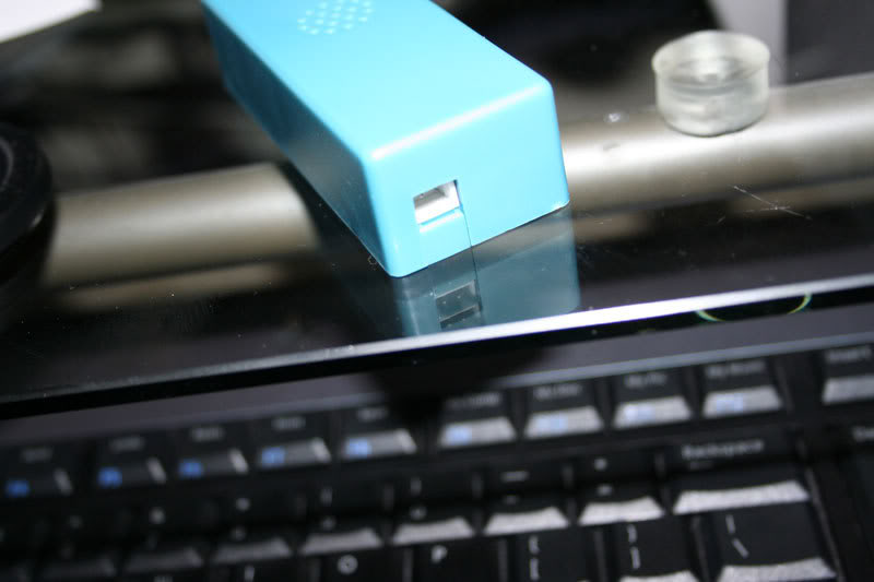
This is for the cathode(s):
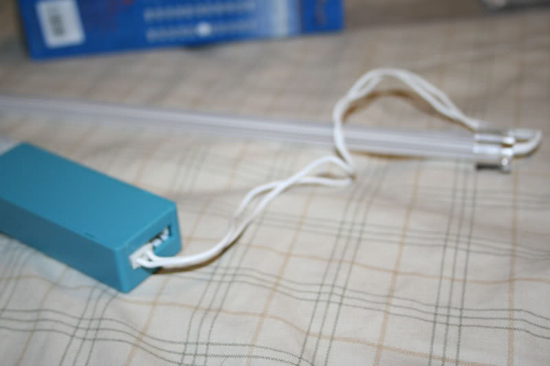
Now go ahead and wire them up:
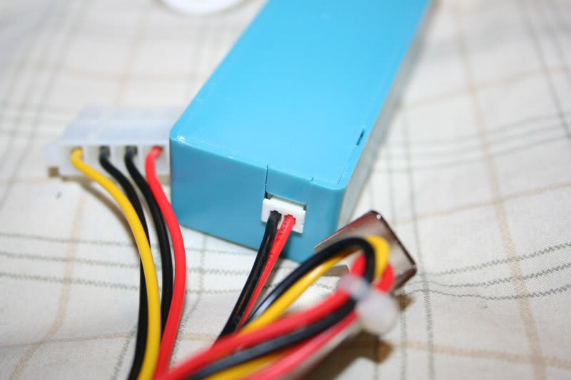
Alright now you need to splice to prep the wiring for power and ground.
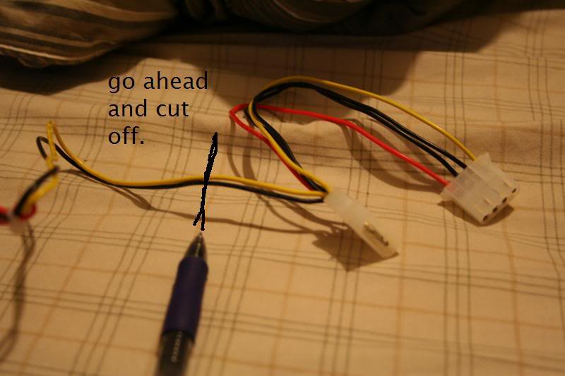
Yellow is power in this case and black is ground:
I have to give some credit to Acree from his LED Door handles thread here:
https://my350z.com/forum/body-interior-exterior-and-lighting-diy/206837-diy-led-door-handles-full-walk-through.html
He basically gave me enough information to be able to wire the lighting from the dome lights.
Necessary materials:
Lighting method
18 gauge wiring
Splicing tool
Electrical tape/Soldering Iron
Large Flathead
Zip Ties/Double sided tape/Whatever necessary to mount.
10mm ratchet to disconnect battery.
First off is to get a hold of what you want to light the footwell. Neons, cathodes, what have you, as long as its powered by 12V then your good to go with wiring things up without resistors.
I chose cathodes because I already had some white ones that were bright and looked great. Got them here:
http://www.svc.com/clk12wt2.html
You will need 2 of these. You will see why.
Now when the kit is in front of you, take out the blue inverter (the blue plastic box), it has two ends:
This is for the wire harness:
This is for the cathode(s):
Now go ahead and wire them up:
Alright now you need to splice to prep the wiring for power and ground.
Yellow is power in this case and black is ground:
Last edited by Voboy; Jun 12, 2007 at 11:39 AM.
Alright now its time to prep the car for workspace. Go ahead and take the ground off the car battery, it'll save you the trouble of replacing a fuse if you mess up with wiring.
I can't stress this enough. Becareful where you put the cathode or neon! Put it in the trunk or something because I've accidentally broken one or two while I was working on this project because I left it in the seat or footwell and tools got placed on it or fell on it and it broke
Dome lights need to come off, pretty simple with a flat head take the two clear plastic peices off first:
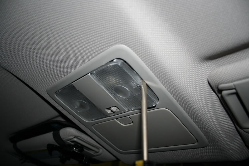
Now the middle peice:
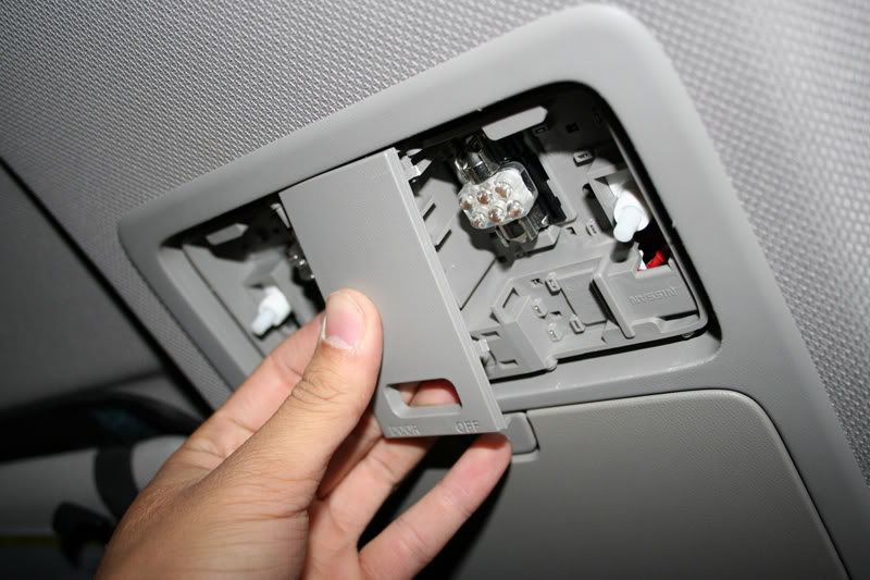
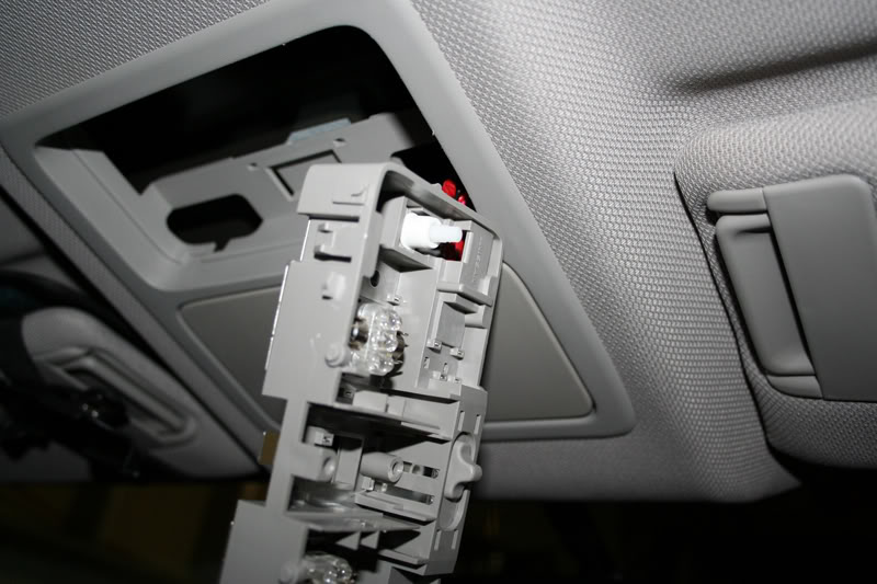
Now the whole map light structure, I went from the bottom with a flat head and popped it out:
I worked on the passenger side first as it was easier to work without the steering wheel in front of you.
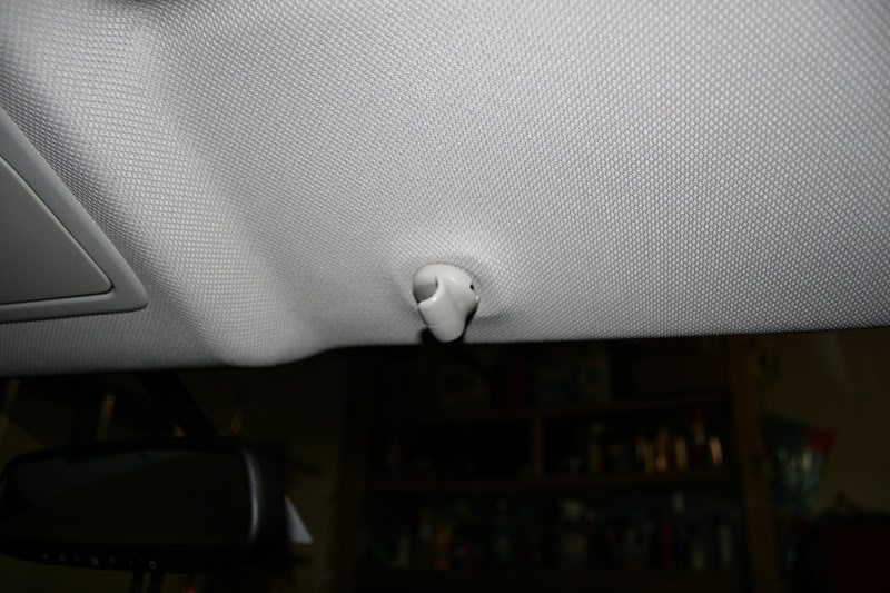
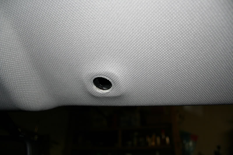
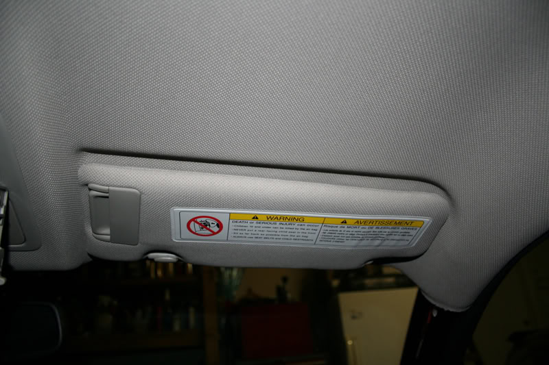
Now for the sun visor:
Twist 90 degrees and pull straight down:
Pop off the cap covering up the two screws and then take apart:
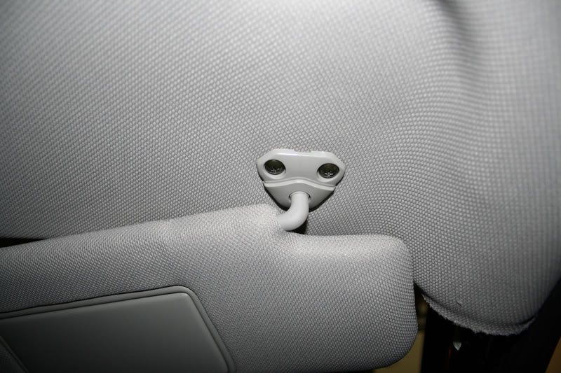
From here you can either let the visor hang from the power wire for the visor mirror light, or you can disconnect it and put it else where.
Next up is the A pillar:
I used a flathead to pop out this piece:
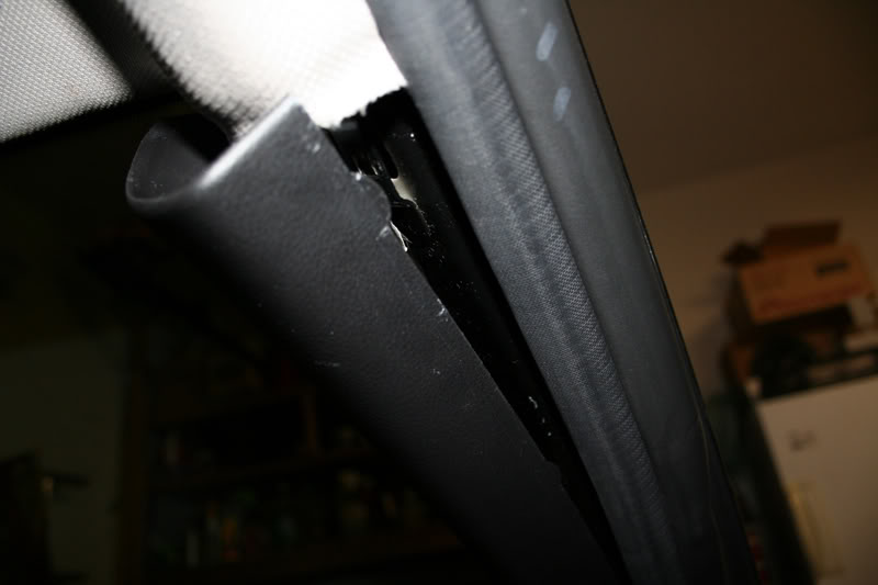
Then pull forcefully:

I can't stress this enough. Becareful where you put the cathode or neon! Put it in the trunk or something because I've accidentally broken one or two while I was working on this project because I left it in the seat or footwell and tools got placed on it or fell on it and it broke
Dome lights need to come off, pretty simple with a flat head take the two clear plastic peices off first:
Now the middle peice:
Now the whole map light structure, I went from the bottom with a flat head and popped it out:
I worked on the passenger side first as it was easier to work without the steering wheel in front of you.
Now for the sun visor:
Twist 90 degrees and pull straight down:
Pop off the cap covering up the two screws and then take apart:
From here you can either let the visor hang from the power wire for the visor mirror light, or you can disconnect it and put it else where.
Next up is the A pillar:
I used a flathead to pop out this piece:
Then pull forcefully:
Last edited by Voboy; Jun 12, 2007 at 11:42 AM.
Alright now that everythings pretty set its time to trail some wiring down the headliner and pillar to get to the footwell cleanly.
I trailed down 18 guage speaker wire I had laying around. I didn't know how the headliner came apart in the front even after removing the visors from drivers and passenger side I was still puzzled at what was keeping the headliner up in the middle.
I pulled down a little forcefully without damaging the headliner and taped the speaker wire to a strong/thick long zip tie and pushed it through the headliner until I felt it through the opening of the dome lights. It's a huge pain, because the area is so small. If someone figures out how to take apart the headliner in the front it might be a little easier.
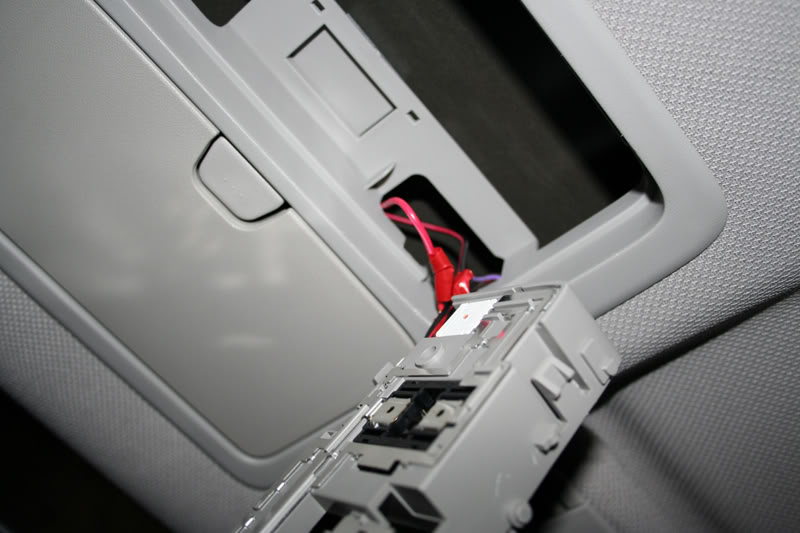
Anyway from here I sliced into the red and purple wires that power the dome lights, and wired the speaker wire to them.
The pink wire is positive and the purple wire is negative. Using colored speaker wire will help you remember whats what. I used red and black speaker wire and electrical taped the wiring as best I can. You guys can solder too but whatever works.
Now trail the speaker wire across the top of the headliner and tuck:
Trail it down the a-pillar, keep in mind to tape/zip tie the wiring down to other wires to keep from rattling:
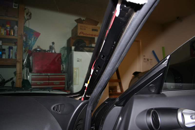
Trail in between the ac and plastic:
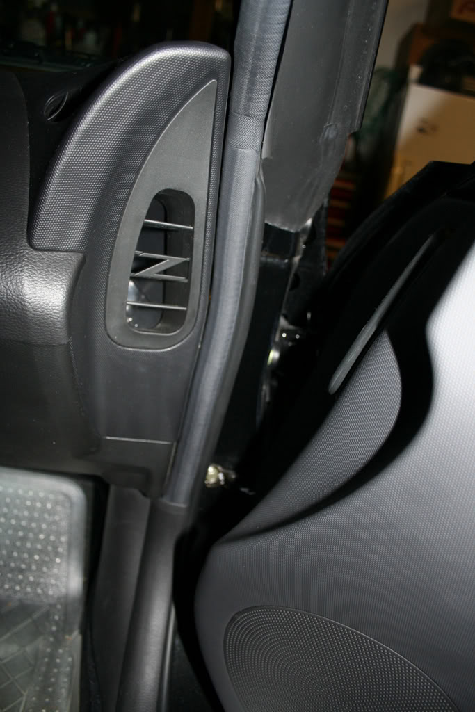
Then down to footwells:
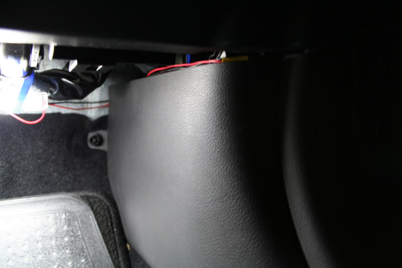
The rest shouldn't be too bad. Wire up the harness to your speaker wiring, power and ground. Test everything out now before mount up the cathodes just incase somethings somethings wrong.
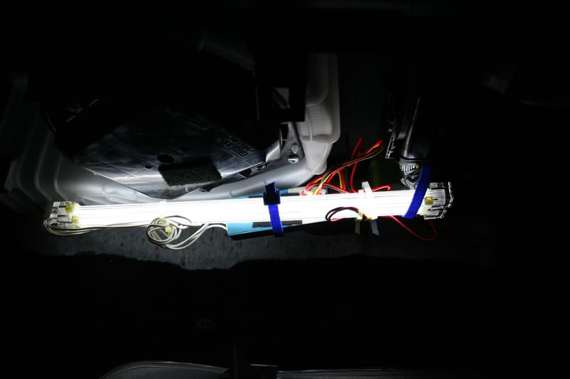
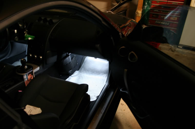
I mounted the cathodes and inverter with zip dies and strong double sided tape. Remember cathodes/neons are very fragile so don't zip tie too tightly. Just firm enough to stay w/o rattling. I accidentally busted a cathode in this process
You can't tell from the pic but I used 1 cathode on the drivers side and 2 on the passenger side. For some reason the drivers side looked brighter at first so I put another to try to even it out.
The ugly:
Now if the cathode didn't light up when you plugged the ground back into the battery:
1. Make sure the switch on the harness is in the ON position.
2. Your door is open.
I trailed down 18 guage speaker wire I had laying around. I didn't know how the headliner came apart in the front even after removing the visors from drivers and passenger side I was still puzzled at what was keeping the headliner up in the middle.
I pulled down a little forcefully without damaging the headliner and taped the speaker wire to a strong/thick long zip tie and pushed it through the headliner until I felt it through the opening of the dome lights. It's a huge pain, because the area is so small. If someone figures out how to take apart the headliner in the front it might be a little easier.
Anyway from here I sliced into the red and purple wires that power the dome lights, and wired the speaker wire to them.
The pink wire is positive and the purple wire is negative. Using colored speaker wire will help you remember whats what. I used red and black speaker wire and electrical taped the wiring as best I can. You guys can solder too but whatever works.
Now trail the speaker wire across the top of the headliner and tuck:
Trail it down the a-pillar, keep in mind to tape/zip tie the wiring down to other wires to keep from rattling:
Trail in between the ac and plastic:
Then down to footwells:
The rest shouldn't be too bad. Wire up the harness to your speaker wiring, power and ground. Test everything out now before mount up the cathodes just incase somethings somethings wrong.
I mounted the cathodes and inverter with zip dies and strong double sided tape. Remember cathodes/neons are very fragile so don't zip tie too tightly. Just firm enough to stay w/o rattling. I accidentally busted a cathode in this process
You can't tell from the pic but I used 1 cathode on the drivers side and 2 on the passenger side. For some reason the drivers side looked brighter at first so I put another to try to even it out.
The ugly:
Now if the cathode didn't light up when you plugged the ground back into the battery:
1. Make sure the switch on the harness is in the ON position.
2. Your door is open.
Last edited by Voboy; Jun 12, 2007 at 11:46 AM.
Like an idiot I was thinking and went through the same steps for the drivers side, when I didn't need to.
Now the drivers side all you need to do is run power and ground over from the passenger side. Tap into the speaker wire you've already ran down the a-pillar and run it over to the drivers side through the middle. Sounds much easier than doing doing it how I did it! By the way this is why you need two cathode packages. The inverter to cathode wiring is too short to be able to wire one cathode to the passenger side and one to the drivers side. I've tried extending the cathode wiring also and it doesn't work. Cathodes would not light up normally with extension.
Tuck in your wires of course as best you can. I didn't have any visible wires after I was done unless you really looked for it so the install is pretty clean when your done except for underneath. Who sticks their head down there? :P
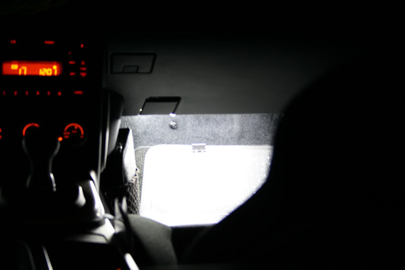
Final Results, bad pics w/o tripod ftl (Will update with tripod later) :
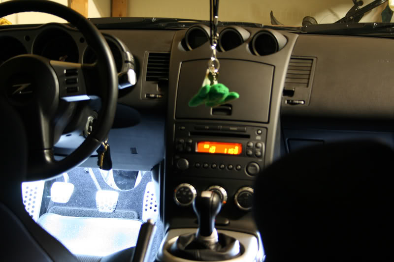
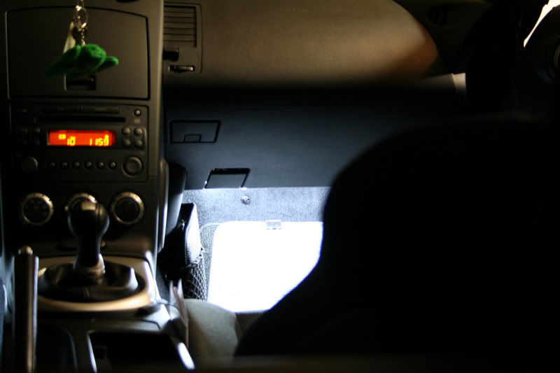
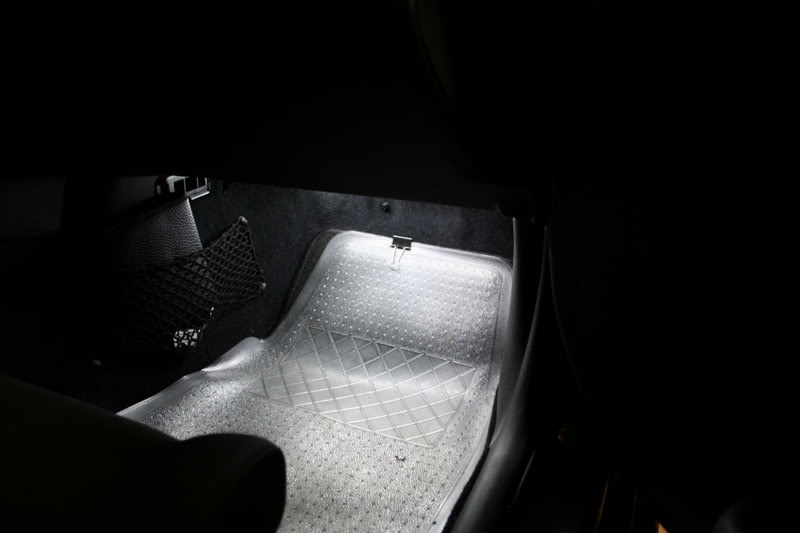
More pics here in this thread at night w/ tripod:
https://my350z.com/forum/showthread....twell+lighting
Now the drivers side all you need to do is run power and ground over from the passenger side. Tap into the speaker wire you've already ran down the a-pillar and run it over to the drivers side through the middle. Sounds much easier than doing doing it how I did it! By the way this is why you need two cathode packages. The inverter to cathode wiring is too short to be able to wire one cathode to the passenger side and one to the drivers side. I've tried extending the cathode wiring also and it doesn't work. Cathodes would not light up normally with extension.
Tuck in your wires of course as best you can. I didn't have any visible wires after I was done unless you really looked for it so the install is pretty clean when your done except for underneath. Who sticks their head down there? :P
Final Results, bad pics w/o tripod
ftl (Will update with tripod later) :More pics here in this thread at night w/ tripod:
https://my350z.com/forum/showthread....twell+lighting
Last edited by Voboy; Jun 12, 2007 at 11:48 AM.
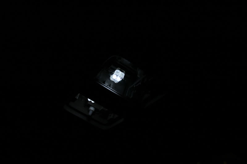
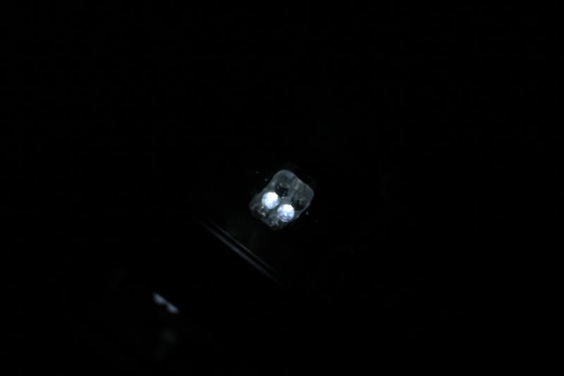
Well since you were in the middle of doing this already, you can go ahead and chance your bulbs for the dome lights if you'd like. I had some LED's from autolumination which are notorious for burning out. And here is an example of the bad soldering points. Here 4 of 6 LED's fail to light up:
What it should look like:
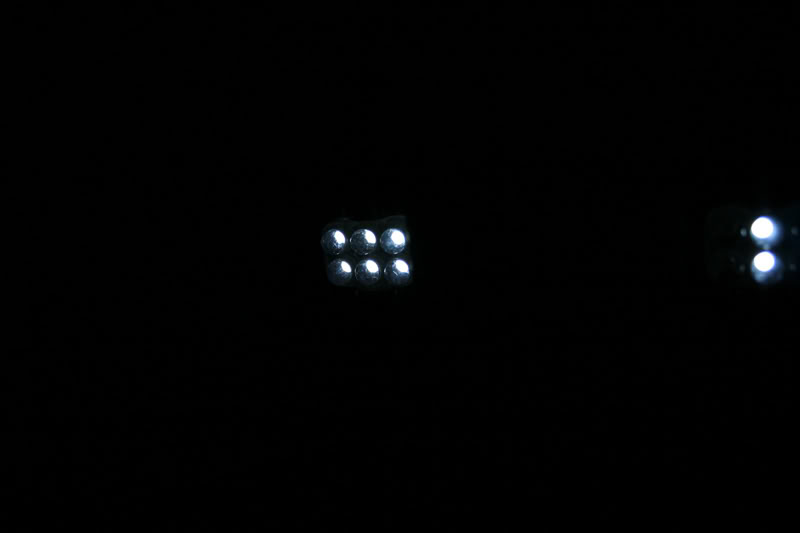
Customer service is pretty good though. I emailed them about the sitiuation and they offered me a replacement bulb at a cheaper price. Had I noticed that only 2 or the 6 LED's didn't work sooner I may have recieved a free replacement. But I emailed them about it after 5 months of ownership when I finally noticed.
I don't leave the dome lights to light on door open so they've lasted me half a year now. I noticed when they're left on the doors they're not completely off. They're still enough juice running through that they are very dimly lit. That may be why the life span of the LED's are so short too.
Anywho final results:
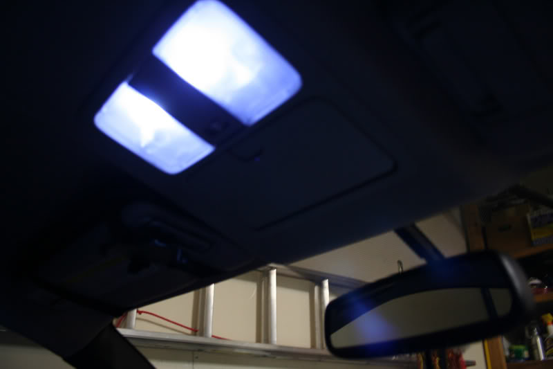
What it should look like:
Customer service is pretty good though. I emailed them about the sitiuation and they offered me a replacement bulb at a cheaper price. Had I noticed that only 2 or the 6 LED's didn't work sooner I may have recieved a free replacement. But I emailed them about it after 5 months of ownership when I finally noticed.
I don't leave the dome lights to light on door open so they've lasted me half a year now. I noticed when they're left on the doors they're not completely off. They're still enough juice running through that they are very dimly lit. That may be why the life span of the LED's are so short too.
Anywho final results:
Last edited by Voboy; Jun 12, 2007 at 11:49 AM.
Originally Posted by first350
looks good! When do you turn on the footwell lighting?
-Peter
-Peter
Trending Topics


i just hooked up 2 each 15" varad led tubes blue
tiestrapped under dash illuminating the entire footwell area in blue
can't see the led's just the accent lighting they produce
installed a switch under the dash for on and off
ran 12v power lead from fuse box by driver left kick panel to switch
ground from switch to left of steering column
hook up + wire leads from led's to load pin on switch
hooked up - wire leads from led's to ground swith pin
total time for install 1 hour taking your time
Last edited by 350zspl; Dec 14, 2006 at 06:16 PM. Reason: installed


Originally Posted by Paul350Z
I did mine in blue and tapped the wires down at the door pins.

Originally Posted by Paul350Z
I did mine in blue and tapped the wires down at the door pins.
http://i6.photobucket.com/albums/y21...eflector10.jpg
http://i6.photobucket.com/albums/y21...eflector10.jpg
Originally Posted by reptile718
That looks awesome. If you dont mind me asking what kind of lighting did you use and where can I get it? Thanks.