
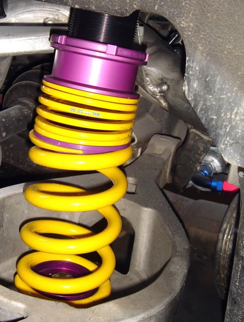
NEW - Stance 3-way Coilovers


Originally Posted by MoodDude
I know this is a true rear coilover set up and mounts on the rear damper position. my question is, the Z was not designed for the suspension to have the load at this point, and neither was the frame that holds the rear damper. Has anyone had a failure on a Stance? Does anyone track a set of Stace coilovers and see any additional fatigue or failures?
What we found was no one mounts the spring directly to the spindle like these "true coil-over" set-ups do from an OEM standpoint for two major reasons: flex and angle of declination change. Any OEM would either mount the damper body directly to the spindle or knuckle via a strut body, so that it is rigid to avoid flex, or.. mount the damper to the bottom of the spindle or knuckle in a perpendicular angle such as the S13, S14, R33, R34, Z32, etc. do.
When mounted to the top of the spindle on an unequal length upper and lower control arm set-up like the Z33, the damper goes through an angle of declination change as the spindle goes through it's motion. The spindle swings in an arc as it goes from full extension to full compression, and back again. This is nothing new, all double wishbones and most multilinks do this to gain negative camber in compression. This is the reason we need to alter camber so much on lowered cars. Now, if the damper was mounted solid like a strut, then the spindle (or knuckle on the front) wouldn't go through that same arc, and the damper and spring would compress in an almost complete linear fashion. (even struts gain some negative camber though, and since it cannot alter it's angle to the knuckle, struts can undergo some serious side loading forces, and that's why a lot of racing struts are inverted) If the damper was mounted on the bottom of the spindle, then as the spindle goes up into it's arc and gains negative camber the damper would have a very minimal change in its angle to the spindle since the top of the spindle is seeing a realatively greater camber change than the bottom. Remember, the upper arms are shorter than the bottom arms on the rear, so when the suspension compresses, the upper arms pull the top of the spindle in towards the car relative to the lower arms and the bottom of the spindle.
So, when the damper is attached at the top of the spindle two things happen that aren't good for spring mounting. The first is that the damper is attached parallel to the spindle body, so that its mounting angle can change as the spindle rotates through it's arc. A perpendicular mounting like on the Z32 would bind the bushing and limit this change, since the upward movement compresses against the damper mount. Again, on the Z32, the damper was mounted on the lowest part of the spindle to limit any angle change and deflection. Now, this angle change occurs because the bottom of the damper must move inboard and outboard relative to the body of the car as the spindle it's attached to moves through its arc. The top of the damper is of course fixed rigid and cannot move, so this changes the angle the damper is positioned at. If a spring is mounted on this damper, then the spring's effective rate is changed as the angle of declination changes. We figure the rear damper declines a total of 11 degrees through it's full motion. The corresponding spring rate is affected by the Cosine of the angle of change, or .982. If you have a 500 lb/in linear spring rate, that means it is now a variable spring rate from 500 to 490 lb/in. Not that big of a change, but it is one reason motorsport guys like Unitech don't mount it there. It gets really bad when you use a progressive rate spring.
Second is the fact that the damper is mounted on an extension that extends inboard to the body (to allow a better tire clearance). The dimensions we took of the rear spindle and mounting positions shows that a considerable amount of force is placed on the damper when it is also asked to carry the sprung weight. This goes back to the reason why OEM's are mounting the damper on the lower part of the spindle (or on the lower control arm like on the front suspension or stock rear spring location). Placing the sprung weight there, shifts the sprung weight during lateral transition to the top of the spindle and acts directly against the inboard motion the suspension is going through. We figured this would cause some issues at the contact patch and have a serious tendancy toward snap oversteer conditions, especially when you consider the heinous amount of anti-squat incorporated into the Z33's rear design. This also posed a serious question of duability since that upper spindle extension is not designed to handle the sprung mass, especially during serious road racing conditions that would place the lateral load transfer in direct opposition to the spindle movement. See, as the car turns, all that weight that is transferred outboard will push down and out on the upper part of the spindle, as the spindle is being compressed up and in towards the body. Not too good, and we see that little extension the damper is mounted on needing some good reinforcement to accomodate the extra stress. I think someone already said that bushings are wearing there, and it's no surprise.
Now, this is just our own musings with some basic measures taken. But, it all stands to reason and makes perfect sense, and explains why no one in professional motorsport is doing this, like the Grand-Am cars and FIA GT2 cars in Europe that have the option.
So, why even have the damper on the spindle at all? Because the dampers job is done best when it is directly atached to the hub mount (spindle in this case, knuckle in the front) Nissan also saw the terrible amount of friction taking place when the spring is attched directly to the spindle (or knuckle) and claims a 60% reduction in friction over the Z32 suspension or comparable strut set-ups (remember what I wrote earlier about how even rigid mounted struts have some negative camber gain and so do the bottom mounted damper positions, and so there is a binding that occurs and extra friction is the result) The optimum, if not using some kind of inboard group-C layout, is to have the springs acting on the lower control arm. This is what Nissan has done. It might not look sexy but it works, just as it has for many BMW and Porsche racing cars that have also used the same design. Mounting a sperate spring on the damper for the purpose of adding pre-load for full extension would make sense since the sprung mass is still supported on the lower control arm, and I think that is what Top Secret did.
Now, I'm sure this will work for almost everyone to have a "true coil-over" in the rear since most don't track or push the chassis to those limits, but I would be surprised to ever see it on a professionally campaigned Z. I think those that do this and campaign, will have problems later because of it. But that's just my somewhat educated opinion.
Will
Edit: BTW: all springs mounted on the damper body will have a 1:1 motion ratio, multiplied by the Cos of the declination angle. There is NO motion ratio due to suspension arm movement in this position (like on the front suspension or stock rear spring location), since the spring is not on a control arm. The spring is acting directly on the spindle, so if the spindle moves an inch up from going over a bump in the road, the spring is compressed a full inch (multiplied by the Cos of the declination angle, of course
 )
)
Last edited by Resolute; Apr 22, 2007 at 05:27 PM.

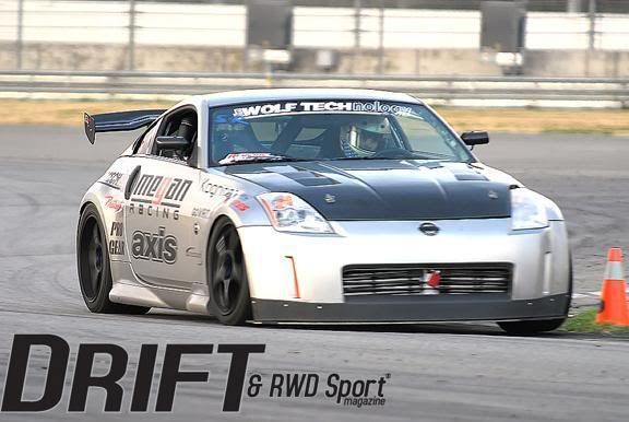
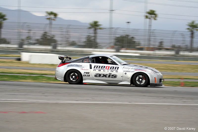
I have helped to develop the Stance true coilover a couple years ago, and am currently in negotiations with them to manufacture, and private label my own brand of this type coilover, except made of aluminum and with my own spring rates & shock valving. We have run this Stance true coil-over in our Time Attack cars for over a year now without any issue. I know Eagle1 has them because I recommended them to him after I did the Sport Compact Car Magazine test for them in that car (white G35 coupe) and we installed them on his car when I was still with VRT.
IMO, this type of shock mounting and its true coilover is superior to the inboard OEM Z33 spring mounting perch, and I do have an engineering degree . (not just a student) Here is some pics for you, I am sure you have no doubt that we track this car very hard.........

IMO, this type of shock mounting and its true coilover is superior to the inboard OEM Z33 spring mounting perch, and I do have an engineering degree
. (not just a student) Here is some pics for you, I am sure you have no doubt that we track this car very hard.........
Last edited by WA2GOOD; Apr 22, 2007 at 06:45 PM.
Originally Posted by WA2GOOD
IMO, this type of shock mounting and its true coilover is superior to the inboard OEM Z33 spring mounting perch, and I do have an engineering degree . (not just a student) Here is some pics for you, I am sure you have no doubt that we track this car very hard.........
. (not just a student) Here is some pics for you, I am sure you have no doubt that we track this car very hard.........As far as superior to OEM... ok. I don't think there is anything to say that the level of engineering put into the design of the suspension layout from Nissan is so easily improved upon. The data on this suggests the spring on damper set-up is worse off. Even if you have success with this set-up, the effective spring rate being altered by the Cosine of angle of declination is a fact of design on any spring anywhere that is not vertical through it's motion, whether it be on a strut or the top of the spindle. The damper body changing angle through the full range of motion on the Z is a fact, we happened to measure an overall change of 11 degrees. The suspension design of the rear of the Z will pull the top of the spindle closer to the chassis than the rear during compression travel, and vise versa on extension- that's a fact. The lateral loads acting on the outboard side of the chassis in a turn will load the spring and work to force the top of the spindle down and away from the car, that's a fact of the design. If the spring load was on the lower control arm as on the front design and OEM rear, or at least on the bottom of the spindle, then it would be working in conjunction with the natural movement of the suspension and not against it. That's all fact of design.
If none of these things have affected your cars laptimes compared to a conventional set-up, then that's great. I really do wish your company good fortune and hope this works for your customers, and hope you don't think I'm out to sabotage business or just talk crap about products for watever reason. There is simply very compelling data against this design, and very little going for it from what we can see. Mood dude posted a legit question, and I gave a legit answer to it.
Will
BTW, I have seen Eagle's car, and I'm glad to see someone running a harmonic damper instead of being so quick to put a UR pulley on it. It's a nice ride.

Sometimes the discipline of what is thought to be good business interfers and casts aside other absolute disicplines that we hope not one is the wiser for. What we say, actually do or produce and then encourage other's to do in like kind are the ultimate witnesses to what anyone is really about or to what motivates them.
Resolute,
My post was in no way supposed to be a stab at you, I was just sharing with you that in our "tried and true, real world track testing", we have found no disadvantages with the true coilovers yet. In fact, quite the opposite. And being an engineer yourself, you should also know that sometimes what is found to work out on paper, doesn't always work out in the application/implementation on the track. That is why there is track testing. When I tested for Goodyear tire and rubber company, we saw a lot of this. They would be the first ones to back up that statement. I do applaud your research though, I just thought people should know my findings as well.
My post was in no way supposed to be a stab at you, I was just sharing with you that in our "tried and true, real world track testing", we have found no disadvantages with the true coilovers yet. In fact, quite the opposite. And being an engineer yourself, you should also know that sometimes what is found to work out on paper, doesn't always work out in the application/implementation on the track. That is why there is track testing. When I tested for Goodyear tire and rubber company, we saw a lot of this. They would be the first ones to back up that statement. I do applaud your research though, I just thought people should know my findings as well.

Scott --
What is up with your coilover development, how far out is this from being available and what kind of setup is it going to be? Adjustability? (If you can give that info out yet.)
What is up with your coilover development, how far out is this from being available and what kind of setup is it going to be? Adjustability? (If you can give that info out yet.)

Registered User
Joined: Dec 2005
Posts: 53
Likes: 0
From: Jesusland
Originally Posted by Resolute
Well first off, we also have BSME degrees if that really matters here. If you have the same, then good for you. That just means you know the degree covers information a mile wide and an inch deep, no matter your emphasis. Do you have a master's in Motorsport Engineering? If not, then I'm inclined to take his professional opinion on this as an equal to yours, even if he is still just a graduate student. I have volunteered some hours with the school's prototype racer program, and have no doubt about the quality of Motorsport Engineers they produce. Know anyone at 3R Racing here in Denver? They have two graduates from this program running their Vipers in Koni World Challenge, as well as some graduates gone off to Champ Car. These guys know their stuff, and I think it's pretty low to knock my post becasue he's a graduate student and we did this on the side as a fun project without the school's support.
As far as superior to OEM... ok. I don't think there is anything to say that the level of engineering put into the design of the suspension layout from Nissan is so easily improved upon. The data on this suggests the spring on damper set-up is worse off. Even if you have success with this set-up, the effective spring rate being altered by the Cosine of angle of declination is a fact of design on any spring anywhere that is not vertical through it's motion, whether it be on a strut or the top of the spindle. The damper body changing angle through the full range of motion on the Z is a fact, we happened to measure an overall change of 11 degrees. The suspension design of the rear of the Z will pull the top of the spindle closer to the chassis than the rear during compression travel, and vise versa on extension- that's a fact. The lateral loads acting on the outboard side of the chassis in a turn will load the spring and work to force the top of the spindle down and away from the car, that's a fact of the design. If the spring load was on the lower control arm as on the front design and OEM rear, or at least on the bottom of the spindle, then it would be working in conjunction with the natural movement of the suspension and not against it. That's all fact of design.
If none of these things have affected your cars laptimes compared to a conventional set-up, then that's great. I really do wish your company good fortune and hope this works for your customers, and hope you don't think I'm out to sabotage business or just talk crap about products for watever reason. There is simply very compelling data against this design, and very little going for it from what we can see. Mood dude posted a legit question, and I gave a legit answer to it.
Will
BTW, I have seen Eagle's car, and I'm glad to see someone running a harmonic damper instead of being so quick to put a UR pulley on it. It's a nice ride.
Originally Posted by Mechee
One can always make an argument for why something is theoretically "better" than something else. However this doesn't mean much until it's actually quantified. That is, exactly how much "better" are we talking? What is the impact of a 0.4% variance in effective spring rate over the full range of suspension travel in the rear? How does 0.4% compare to natural variances in effective spring rate of non-ideal springs in the first place? Regarding applied forces on the rear spindles, these are constrained assemblies with one degree of freedom, so could you please give more detail on what you mean by disadvantages from where this force is applied (besides just stress distributions in the spindle itself)? Assuming there is some relevant argument here, can you quantify these differences relative to other loads in the system during common vehicle dynamics?

While I would love to say that we had personal access to equipment that costs hundreds of thousands of dollars to give a full MBS (multibody systems) analysis with downloadable ADAMS models for you... I can't. Something about personal use and school funding, blah, blah, blah... However, to elaborate the dynamics involved during load transfer between the two systems, and the diference from simple compression due to road surface irregularities, I'll give it a shot. I might even use some craptastic home-made diagrams. Or maybe not, let me see what I can type up and I'll post it here after digging up our musings and findings. As far as being quantitative, I can supply our mathematical formulas and calculations, but as I stated, I have no modelling for analysis. The formulas used come from several textbooks and SAE papers, and I'll try and make a decent post from our summaries of them. Stay tuned, I'll probably make it a seperate thread, as this is beyond the scope of the OP. I feel I answered a question posted about the location of these coi-overs, and so has Wa2good, and it's off topic to delve into the mechanics of it.
Will
Originally Posted by Resolute
Here's what I know from some testing done by a graduate student at Colorado State University's Motorsport Engineering dept on this idea. It wasn't done by me, just with my help. The guy is a friend of mine and we went to school for our ME's together, and now he's doing his Masters there for Motorsports. For his Racing Dynamics course, we got into a good discussion about this, beause I had the same question.
What we found was no one mounts the spring directly to the spindle like these "true coil-over" set-ups do from an OEM standpoint for two major reasons: flex and angle of declination change. Any OEM would either mount the damper body directly to the spindle or knuckle via a strut body, so that it is rigid to avoid flex, or.. mount the damper to the bottom of the spindle or knuckle in a perpendicular angle such as the S13, S14, R33, R34, Z32, etc. do.
When mounted to the top of the spindle on an unequal length upper and lower control arm set-up like the Z33, the damper goes through an angle of declination change as the spindle goes through it's motion. The spindle swings in an arc as it goes from full extension to full compression, and back again. This is nothing new, all double wishbones and most multilinks do this to gain negative camber in compression. This is the reason we need to alter camber so much on lowered cars. Now, if the damper was mounted solid like a strut, then the spindle (or knuckle on the front) wouldn't go through that same arc, and the damper and spring would compress in an almost complete linear fashion. (even struts gain some negative camber though, and since it cannot alter it's angle to the knuckle, struts can undergo some serious side loading forces, and that's why a lot of racing struts are inverted) If the damper was mounted on the bottom of the spindle, then as the spindle goes up into it's arc and gains negative camber the damper would have a very minimal change in its angle to the spindle since the top of the spindle is seeing a realatively greater camber change than the bottom. Remember, the upper arms are shorter than the bottom arms on the rear, so when the suspension compresses, the upper arms pull the top of the spindle in towards the car relative to the lower arms and the bottom of the spindle.
So, when the damper is attached at the top of the spindle two things happen that aren't good for spring mounting. The first is that the damper is attached parallel to the spindle body, so that its mounting angle can change as the spindle rotates through it's arc. A perpendicular mounting like on the Z32 would bind the bushing and limit this change, since the upward movement compresses against the damper mount. Again, on the Z32, the damper was mounted on the lowest part of the spindle to limit any angle change and deflection. Now, this angle change occurs because the bottom of the damper must move inboard and outboard relative to the body of the car as the spindle it's attached to moves through its arc. The top of the damper is of course fixed rigid and cannot move, so this changes the angle the damper is positioned at. If a spring is mounted on this damper, then the spring's effective rate is changed as the angle of declination changes. We figure the rear damper declines a total of 11 degrees through it's full motion. The corresponding spring rate is affected by the Cosine of the angle of change, or .982. If you have a 500 lb/in linear spring rate, that means it is now a variable spring rate from 500 to 490 lb/in. Not that big of a change, but it is one reason motorsport guys like Unitech don't mount it there. It gets really bad when you use a progressive rate spring.
Second is the fact that the damper is mounted on an extension that extends inboard to the body (to allow a better tire clearance). The dimensions we took of the rear spindle and mounting positions shows that a considerable amount of force is placed on the damper when it is also asked to carry the sprung weight. This goes back to the reason why OEM's are mounting the damper on the lower part of the spindle (or on the lower control arm like on the front suspension or stock rear spring location). Placing the sprung weight there, shifts the sprung weight during lateral transition to the top of the spindle and acts directly against the inboard motion the suspension is going through. We figured this would cause some issues at the contact patch and have a serious tendancy toward snap oversteer conditions, especially when you consider the heinous amount of anti-squat incorporated into the Z33's rear design. This also posed a serious question of duability since that upper spindle extension is not designed to handle the sprung mass, especially during serious road racing conditions that would place the lateral load transfer in direct opposition to the spindle movement. See, as the car turns, all that weight that is transferred outboard will push down and out on the upper part of the spindle, as the spindle is being compressed up and in towards the body. Not too good, and we see that little extension the damper is mounted on needing some good reinforcement to accomodate the extra stress. I think someone already said that bushings are wearing there, and it's no surprise.
Now, this is just our own musings with some basic measures taken. But, it all stands to reason and makes perfect sense, and explains why no one in professional motorsport is doing this, like the Grand-Am cars and FIA GT2 cars in Europe that have the option.
So, why even have the damper on the spindle at all? Because the dampers job is done best when it is directly atached to the hub mount (spindle in this case, knuckle in the front) Nissan also saw the terrible amount of friction taking place when the spring is attched directly to the spindle (or knuckle) and claims a 60% reduction in friction over the Z32 suspension or comparable strut set-ups (remember what I wrote earlier about how even rigid mounted struts have some negative camber gain and so do the bottom mounted damper positions, and so there is a binding that occurs and extra friction is the result) The optimum, if not using some kind of inboard group-C layout, is to have the springs acting on the lower control arm. This is what Nissan has done. It might not look sexy but it works, just as it has for many BMW and Porsche racing cars that have also used the same design. Mounting a sperate spring on the damper for the purpose of adding pre-load for full extension would make sense since the sprung mass is still supported on the lower control arm, and I think that is what Top Secret did.
Now, I'm sure this will work for almost everyone to have a "true coil-over" in the rear since most don't track or push the chassis to those limits, but I would be surprised to ever see it on a professionally campaigned Z. I think those that do this and campaign, will have problems later because of it. But that's just my somewhat educated opinion.
Will
Edit: BTW: all springs mounted on the damper body will have a 1:1 motion ratio, multiplied by the Cos of the declination angle. There is NO motion ratio due to suspension arm movement in this position (like on the front suspension or stock rear spring location), since the spring is not on a control arm. The spring is acting directly on the spindle, so if the spindle moves an inch up from going over a bump in the road, the spring is compressed a full inch (multiplied by the Cos of the declination angle, of course )
What we found was no one mounts the spring directly to the spindle like these "true coil-over" set-ups do from an OEM standpoint for two major reasons: flex and angle of declination change. Any OEM would either mount the damper body directly to the spindle or knuckle via a strut body, so that it is rigid to avoid flex, or.. mount the damper to the bottom of the spindle or knuckle in a perpendicular angle such as the S13, S14, R33, R34, Z32, etc. do.
When mounted to the top of the spindle on an unequal length upper and lower control arm set-up like the Z33, the damper goes through an angle of declination change as the spindle goes through it's motion. The spindle swings in an arc as it goes from full extension to full compression, and back again. This is nothing new, all double wishbones and most multilinks do this to gain negative camber in compression. This is the reason we need to alter camber so much on lowered cars. Now, if the damper was mounted solid like a strut, then the spindle (or knuckle on the front) wouldn't go through that same arc, and the damper and spring would compress in an almost complete linear fashion. (even struts gain some negative camber though, and since it cannot alter it's angle to the knuckle, struts can undergo some serious side loading forces, and that's why a lot of racing struts are inverted) If the damper was mounted on the bottom of the spindle, then as the spindle goes up into it's arc and gains negative camber the damper would have a very minimal change in its angle to the spindle since the top of the spindle is seeing a realatively greater camber change than the bottom. Remember, the upper arms are shorter than the bottom arms on the rear, so when the suspension compresses, the upper arms pull the top of the spindle in towards the car relative to the lower arms and the bottom of the spindle.
So, when the damper is attached at the top of the spindle two things happen that aren't good for spring mounting. The first is that the damper is attached parallel to the spindle body, so that its mounting angle can change as the spindle rotates through it's arc. A perpendicular mounting like on the Z32 would bind the bushing and limit this change, since the upward movement compresses against the damper mount. Again, on the Z32, the damper was mounted on the lowest part of the spindle to limit any angle change and deflection. Now, this angle change occurs because the bottom of the damper must move inboard and outboard relative to the body of the car as the spindle it's attached to moves through its arc. The top of the damper is of course fixed rigid and cannot move, so this changes the angle the damper is positioned at. If a spring is mounted on this damper, then the spring's effective rate is changed as the angle of declination changes. We figure the rear damper declines a total of 11 degrees through it's full motion. The corresponding spring rate is affected by the Cosine of the angle of change, or .982. If you have a 500 lb/in linear spring rate, that means it is now a variable spring rate from 500 to 490 lb/in. Not that big of a change, but it is one reason motorsport guys like Unitech don't mount it there. It gets really bad when you use a progressive rate spring.
Second is the fact that the damper is mounted on an extension that extends inboard to the body (to allow a better tire clearance). The dimensions we took of the rear spindle and mounting positions shows that a considerable amount of force is placed on the damper when it is also asked to carry the sprung weight. This goes back to the reason why OEM's are mounting the damper on the lower part of the spindle (or on the lower control arm like on the front suspension or stock rear spring location). Placing the sprung weight there, shifts the sprung weight during lateral transition to the top of the spindle and acts directly against the inboard motion the suspension is going through. We figured this would cause some issues at the contact patch and have a serious tendancy toward snap oversteer conditions, especially when you consider the heinous amount of anti-squat incorporated into the Z33's rear design. This also posed a serious question of duability since that upper spindle extension is not designed to handle the sprung mass, especially during serious road racing conditions that would place the lateral load transfer in direct opposition to the spindle movement. See, as the car turns, all that weight that is transferred outboard will push down and out on the upper part of the spindle, as the spindle is being compressed up and in towards the body. Not too good, and we see that little extension the damper is mounted on needing some good reinforcement to accomodate the extra stress. I think someone already said that bushings are wearing there, and it's no surprise.
Now, this is just our own musings with some basic measures taken. But, it all stands to reason and makes perfect sense, and explains why no one in professional motorsport is doing this, like the Grand-Am cars and FIA GT2 cars in Europe that have the option.
So, why even have the damper on the spindle at all? Because the dampers job is done best when it is directly atached to the hub mount (spindle in this case, knuckle in the front) Nissan also saw the terrible amount of friction taking place when the spring is attched directly to the spindle (or knuckle) and claims a 60% reduction in friction over the Z32 suspension or comparable strut set-ups (remember what I wrote earlier about how even rigid mounted struts have some negative camber gain and so do the bottom mounted damper positions, and so there is a binding that occurs and extra friction is the result) The optimum, if not using some kind of inboard group-C layout, is to have the springs acting on the lower control arm. This is what Nissan has done. It might not look sexy but it works, just as it has for many BMW and Porsche racing cars that have also used the same design. Mounting a sperate spring on the damper for the purpose of adding pre-load for full extension would make sense since the sprung mass is still supported on the lower control arm, and I think that is what Top Secret did.
Now, I'm sure this will work for almost everyone to have a "true coil-over" in the rear since most don't track or push the chassis to those limits, but I would be surprised to ever see it on a professionally campaigned Z. I think those that do this and campaign, will have problems later because of it. But that's just my somewhat educated opinion.
Will
Edit: BTW: all springs mounted on the damper body will have a 1:1 motion ratio, multiplied by the Cos of the declination angle. There is NO motion ratio due to suspension arm movement in this position (like on the front suspension or stock rear spring location), since the spring is not on a control arm. The spring is acting directly on the spindle, so if the spindle moves an inch up from going over a bump in the road, the spring is compressed a full inch (multiplied by the Cos of the declination angle, of course
)Good to see an educated response! I never considered the angle change to be that big of a deal but I did not know it changed 11 degrees!
I have considered the extra load being placed on the extension from the spindle and was trying to find a way to gusset or reinforce the spindle in that area but it looks pretty tight in there.
I am the one that was speaking about the bushings wearing prematurely and mine are shot making noise over low speed bumps. Its to the point where I am looking for a good adjustable monotube replacement that uses the OEM style spring location. But none of the existing ones go as low as I prefer my car to sit. I suppose the only way to get what I want is custom lower control arms.
One question, you said the motion ratio is 1:1 with the spring mounted on the strut, what is the motion ratio with the spring in the OEM location?

After riding on KW V3's for a few months, and seeing the KW Competition setup, ride height is not an issue if you want to sacrifice shock travel before coil bind. I do not have specific measurements, but if you convert the rear springs to a liner spring, there are PLENTY of different spring sizes that can be used to suit your ride height preference.
Registered User
Joined: Dec 2005
Posts: 53
Likes: 0
From: Jesusland
Originally Posted by Resolute
You make it sound like it should be so easy
While I would love to say that we had personal access to equipment that costs hundreds of thousands of dollars to give a full MBS (multibody systems) analysis with downloadable ADAMS models for you... I can't. Something about personal use and school funding, blah, blah, blah... However, to elaborate the dynamics involved during load transfer between the two systems, and the diference from simple compression due to road surface irregularities, I'll give it a shot. I might even use some craptastic home-made diagrams. Or maybe not, let me see what I can type up and I'll post it here after digging up our musings and findings. As far as being quantitative, I can supply our mathematical formulas and calculations, but as I stated, I have no modelling for analysis. The formulas used come from several textbooks and SAE papers, and I'll try and make a decent post from our summaries of them. Stay tuned, I'll probably make it a seperate thread, as this is beyond the scope of the OP. I feel I answered a question posted about the location of these coi-overs, and so has Wa2good, and it's off topic to delve into the mechanics of it.
Will
Originally Posted by Mechee
You don't need to make it very complicated. Simplify the suspension mechanics to a double-wishbone type, and use rough measured lengths for the geometries. Then look at how the forces in the system compare for spring force acting in the stock shock mounting location versus the normal spring perch. The point is to use such back-of-the-envelope calculations as a sanity check to justify your initial concerns. I personally think you will be surprised, but I haven't looked in detail. Even the detailed models are not that complicated, though unnecessary for this argument.
Now, I could simply post the dimensions of the rear suspension and make a simple model, but so could anyone. At CSU there is a machine that takes very precise three dimentional measurements and loads them in a CAD program. I can't use it
So, I'm left to level the car and use a plumb and laser to make measures- which is exactly what we did. They're close enough to matter for our argument here. I have my autocad schemes somewhere of the front and rear suspension. I made them to get motion ratio and instant center, roll center, dimensions a long time ago. I know I still have them, maybe on my old computer. My buddy and I did this almost a year ago, maybe more, and I posted my thoughts back then, and in several posts since- but no one ever really cared. Of course, I don't think I mentioned anything before in a thread where someone was trying to sell somethingIt's good to see so much interest. It makes this forum fun. But I've got more than enough to keep me busy besides trying to explain vehicle dynamics and involve solid mathematics and quantitative data in my post on an internet forum. But, I will put something together and post it. It should be a good discussion, as this has become.
Now, when I dig up my measures ( I could swear I've posted them on this site before) I'l post them. Something to consider: the rear suspension does not behave like a double-wishbone suspension. The traction arm and toe rod ensure that, and there involves the need for some bushing compliance (there is not just one degree of freedom) and some difference in forces between the two systems. Second, if it wasn't clear before, the variability of the effective spring load changes the dynamic transfer of weight in transition, as the shock angle is not only changing on the outboard side but also the inboard side inversely. The damper itself is more affected in this process due to friction and dynamic response being directly related to it. As such, the repeatability of the system is in jeapordy from one corner to another as a new variable of friction and changing loading dynamics is added. In other words, the shock won't behave exactly the same each time. The contact patch is, naturally, affected and this is what I'll attempt to show later.
Will
EDIt: I said "plump & laser" onstead of "plumb & laser". I love late night studies... two more weeks!!
Last edited by Resolute; Apr 25, 2007 at 09:32 PM.
Registered User
Joined: Dec 2005
Posts: 53
Likes: 0
From: Jesusland
Still, we're talking about a peak progressive rate change of cos(11 deg) ~= 1.8% change. 1.8%! Again, what is the natural variance in spring rate for a real world spring over its range of compression?
Regarding the application location of the spring force, I still fail to see why this is of significant consequence. Based on the location, there is some transfer function to applied force along the direction of suspension motion (after all, the rear suspension is fully constrained to one degree of freedom). This is the only direction where work can be done at a given instant. If the spring rates are scaled accordingly to account for the differences in effective force along the direction of suspension motion, then I fail to see the difference from a suspension dynamics viewpoint. Please provide an intuitive explanation for why this is incorrect.
Regarding the application location of the spring force, I still fail to see why this is of significant consequence. Based on the location, there is some transfer function to applied force along the direction of suspension motion (after all, the rear suspension is fully constrained to one degree of freedom). This is the only direction where work can be done at a given instant. If the spring rates are scaled accordingly to account for the differences in effective force along the direction of suspension motion, then I fail to see the difference from a suspension dynamics viewpoint. Please provide an intuitive explanation for why this is incorrect.
Originally Posted by Mechee
Still, we're talking about a peak progressive rate change of cos(11 deg) ~= 1.8% change. 1.8%! Again, what is the natural variance in spring rate for a real world spring over its range of compression?
Originally Posted by Mechee
Regarding the application location of the spring force, I still fail to see why this is of significant consequence. Based on the location, there is some transfer function to applied force along the direction of suspension motion (after all, the rear suspension is fully constrained to one degree of freedom). This is the only direction where work can be done at a given instant. If the spring rates are scaled accordingly to account for the differences in effective force along the direction of suspension motion, then I fail to see the difference from a suspension dynamics viewpoint. Please provide an intuitive explanation for why this is incorrect.
The simplest thing to see, besides the shock deflection, is that the biggest drawback, as I have stated, is the increase in friction over the OEM design. Not only does this affect spring effectiveness, but the shock dynamics as well. Nissan Motorsports says a max reduction of 60%, as I recall we got something else but close. We also had to assume on some variables. That's a reduction in friction for the shock not having to take the side loading associated with carrying the sprung weight on the top of the spindle. It doesn't matter the damper construction or spring type, it's a constant with the suspension layout. You could compensate to a small degree for it with materials and shock construction, but why bother if the OEM location is suitable? The friction associated will, again, reduce repeatability as the friction is a function of weight transfer and as such will vary. Unladen, the friction is a function of damper settings alone- as it should be.
Now, the original question was one of durability, and I think I have supported my claim to extra stress on the spindle, and that should be a given. As far as fatigue goes, who know's the spindle's limits. But that extra stress doesn't just place an extra load on the spindle, it changes the relative dynamic load on the contact patch as well, and that should be a given considering the top of the spindle is acting on a lever arm of it's own in direct opposition to the shock travel and this creates a higher relative wheel rate compared to the spring acting in congruent measure with that upper lever arm. I mean, there is a reason the upper camber arm is attached *above* the spring, and the dynamics of which are understandable.
I think you're looking for some proof or hard data that I don't have ready to give. Nor am I compelled to. The dynamics involved are well known and taught in the motorsports program here, hence why I consulted them on this question. This is not some secret that my friend and I have stumbled on or made up, but is well documented in several fine suspesion and vehicle dynamics books. Any of which I could recommend. I will be the first to say my interpretation could be wrong, or misapplied. I don't think so, but no one has had any real argument one way or another before. I am learning as I go with what is a hobby to me, and I'm not sure what else it is you are looking for that you think is so simple to illustrate, that I have not already said. My apologies, as I said- I've been told plenty I don't communicate my thoughts very clearly.
So, you're the first to be so interested in what I had to say on this in the last year or so. How come? What are your thoughts? Where does it sound off to you? Thanks for your interest in this,
Will
This is my last attempt at making this clear, and maybe it will help. You mention the spindle only having one degree of freedom, but it is not the spindle we are concerned about- it is the forces acting on contact patch through the spindle. Maybe it will help to not visualize the spindle and it's control arms as a single system.
The spindle's motion is a function of four seperate motions from the control arms. The easiest example of how this comes into play is by looking at the traction rod and it's effect. The traction rod is part of the anti-squat geometry of the rear suspension, in conjunction with the upper control arm. The "toe rod" is already acting as a tension/compression ro to control spindle location fore/aft. The traction rod does not need to do this, it is not there for this reason. It's job is to simply provide an upward thrust on the spindle that is a direct reaction to the downward force from acceleration placed on the spindle. Again, it provides a reaction force in direct opposition to the downward thrust from accel. This effectively increases the wheel rate, and thereby places extra load on the contact patch.
If the spring were on the damper, then a similiar situation is at play from a lateral standpoint. As the load is transferred down and out on the outboard suspension, the top of the spindle travels in an arc that is directly opposed to this. The bottom control arm motion is in line with this force, the top of the spindle motion is not. As the vehicle attempts to "roll" about it's roll center, the lower control arm's inboard position drops relative to it's static height. The upper control arm's inboard position also drops relative to it's static height. The outboard side of both arms, as well as the top of the spindle, move upwards relative to the chassis as a reaction to the downward force acting on the control arms. This is where the negative camber gains come from. Another phenomenon known as "jacking" comes into play here, but is minor on the Z33 suspension layout and unless you plan on taking this car into a professional series and want to be competitive, there is no reason to know this phenom exists. Placing the spring on lower control arm is congruent with the motion and direction of forces acting on the contact patch through the spindle. Placing the spring on the top of the spindle means there is now a reactionary force acting on the contact patch through the spindle through the spring loading (just as in anti-squat for longitudinal loads) that effectively increases the rear wheel rate.
This loading can be calculated using the instantaneous center changes that occur and the roll moment, compared to the motion of the suspension members during roll. I still have the formulas for this highlighted in Milliken's book on the subject, and have found the suspension geometry I plotted out. Which reminds me:
Tonywenzel the rear motion ratio is .598 with a measured arm length of 43.5cm from the centerline of the lower ball joint to the centerline of the inboard mount, and the centerline of the spring being placed 26cm from the inboard mount.
I don't know if I'll go through making a new post or not on this. We'll see. I guess this post got hijacked enough and I don't think there is anything more I could try and explain, so I'm done. I'm convinced this is not an improvement over the stock location, and have found only evidence that supports this when looking at other engineer's and designer's parameters for suspension design.
Will
Registered User
Joined: Dec 2005
Posts: 53
Likes: 0
From: Jesusland
Originally Posted by Resolute
This is my last attempt at making this clear, and maybe it will help. You mention the spindle only having one degree of freedom, but it is not the spindle we are concerned about- it is the forces acting on contact patch through the spindle. Maybe it will help to not visualize the spindle and it's control arms as a single system.
The spindle's motion is a function of four seperate motions from the control arms. The easiest example of how this comes into play is by looking at the traction rod and it's effect. The traction rod is part of the anti-squat geometry of the rear suspension, in conjunction with the upper control arm. The "toe rod" is already acting as a tension/compression ro to control spindle location fore/aft. The traction rod does not need to do this, it is not there for this reason. It's job is to simply provide an upward thrust on the spindle that is a direct reaction to the downward force from acceleration placed on the spindle. Again, it provides a reaction force in direct opposition to the downward thrust from accel. This effectively increases the wheel rate, and thereby places extra load on the contact patch.
If the spring were on the damper, then a similiar situation is at play from a lateral standpoint. As the load is transferred down and out on the outboard suspension, the top of the spindle travels in an arc that is directly opposed to this. The bottom control arm motion is in line with this force, the top of the spindle motion is not. As the vehicle attempts to "roll" about it's roll center, the lower control arm's inboard position drops relative to it's static height. The upper control arm's inboard position also drops relative to it's static height. The outboard side of both arms, as well as the top of the spindle, move upwards relative to the chassis as a reaction to the downward force acting on the control arms. This is where the negative camber gains come from. Another phenomenon known as "jacking" comes into play here, but is minor on the Z33 suspension layout and unless you plan on taking this car into a professional series and want to be competitive, there is no reason to know this phenom exists. Placing the spring on lower control arm is congruent with the motion and direction of forces acting on the contact patch through the spindle. Placing the spring on the top of the spindle means there is now a reactionary force acting on the contact patch through the spindle through the spring loading (just as in anti-squat for longitudinal loads) that effectively increases the rear wheel rate.
This loading can be calculated using the instantaneous center changes that occur and the roll moment, compared to the motion of the suspension members during roll. I still have the formulas for this highlighted in Milliken's book on the subject, and have found the suspension geometry I plotted out. Which reminds me:
Tonywenzel the rear motion ratio is .598 with a measured arm length of 43.5cm from the centerline of the lower ball joint to the centerline of the inboard mount, and the centerline of the spring being placed 26cm from the inboard mount.
I don't know if I'll go through making a new post or not on this. We'll see. I guess this post got hijacked enough and I don't think there is anything more I could try and explain, so I'm done. I'm convinced this is not an improvement over the stock location, and have found only evidence that supports this when looking at other engineer's and designer's parameters for suspension design.
Will
The spindle's motion is a function of four seperate motions from the control arms. The easiest example of how this comes into play is by looking at the traction rod and it's effect. The traction rod is part of the anti-squat geometry of the rear suspension, in conjunction with the upper control arm. The "toe rod" is already acting as a tension/compression ro to control spindle location fore/aft. The traction rod does not need to do this, it is not there for this reason. It's job is to simply provide an upward thrust on the spindle that is a direct reaction to the downward force from acceleration placed on the spindle. Again, it provides a reaction force in direct opposition to the downward thrust from accel. This effectively increases the wheel rate, and thereby places extra load on the contact patch.
If the spring were on the damper, then a similiar situation is at play from a lateral standpoint. As the load is transferred down and out on the outboard suspension, the top of the spindle travels in an arc that is directly opposed to this. The bottom control arm motion is in line with this force, the top of the spindle motion is not. As the vehicle attempts to "roll" about it's roll center, the lower control arm's inboard position drops relative to it's static height. The upper control arm's inboard position also drops relative to it's static height. The outboard side of both arms, as well as the top of the spindle, move upwards relative to the chassis as a reaction to the downward force acting on the control arms. This is where the negative camber gains come from. Another phenomenon known as "jacking" comes into play here, but is minor on the Z33 suspension layout and unless you plan on taking this car into a professional series and want to be competitive, there is no reason to know this phenom exists. Placing the spring on lower control arm is congruent with the motion and direction of forces acting on the contact patch through the spindle. Placing the spring on the top of the spindle means there is now a reactionary force acting on the contact patch through the spindle through the spring loading (just as in anti-squat for longitudinal loads) that effectively increases the rear wheel rate.
This loading can be calculated using the instantaneous center changes that occur and the roll moment, compared to the motion of the suspension members during roll. I still have the formulas for this highlighted in Milliken's book on the subject, and have found the suspension geometry I plotted out. Which reminds me:
Tonywenzel the rear motion ratio is .598 with a measured arm length of 43.5cm from the centerline of the lower ball joint to the centerline of the inboard mount, and the centerline of the spring being placed 26cm from the inboard mount.
I don't know if I'll go through making a new post or not on this. We'll see. I guess this post got hijacked enough and I don't think there is anything more I could try and explain, so I'm done. I'm convinced this is not an improvement over the stock location, and have found only evidence that supports this when looking at other engineer's and designer's parameters for suspension design.
Will
Originally Posted by Resolute
So, you're the first to be so interested in what I had to say on this in the last year or so. How come? What are your thoughts? Where does it sound off to you? Thanks for your interest in this,
Will
Will
2) I'm a BSME / MSME myself with some focus on kinematics / vehicle dynamics, and a year or so of work with a vehicle dynamics research lab in grad school. On a side note, I actually work as an EE now (get the screen name?), but there is a special place in my heart for mechanics.
My intuition is that a sufficiently scaled spring rate acting in the shock location would have virtually no relative impact on dynamics. However, I haven't looked at the problem in detail, so I could be wrong (it's happened once before).