When you click on links to various merchants on this site and make a purchase, this can result in this site earning a commission. Affiliate programs and affiliations include, but are not limited to, the eBay Partner Network.
I have the mishimoto fans as well I wired both to high. ignored the low. From what I could tell there are 2 sets of circuits in the OEM harness. one set is high and one set is low. you can wire one high and one low. but I just did high on both.
Bringing this thread back from the dead. I'm in the middle of my install and my wiring doesn't match istans diagram. My wiring from the car goes as follows:
Fan connector 1:
1. Blue 2. light green
3. Yellow 4. Black
Fan connector 2:
1: Blue/white 2. Red
3. Yellow/Red 4. Black
Could anyone please help me match these to istans diagram? I looked in the service manual and don't see any wiring info and I don't have a multimeter on hand!!!
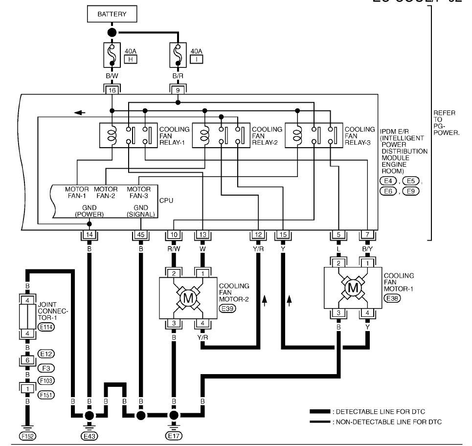
Built my harnesses this weekend. What you are looking at are the extender patch cables, not the actual plug that the OEM manual references. The patch plugs use generic wire colors and are not really documented in the FSM.
When i was doing research there was a thread asking about the designations for cooling fans 1 and 2. Nissan calls the driver side Cooling Fan 2 and the passenger side cooling fan 1. When you wire up the schematics you only need to make sure you wire your passenger side new fan to the Low Pins which are 1 on both OEM connectors. High speed goes to driver side which is Pin 2 on both OEM connectors.
We were reviewing the wiring diagram. I am concerned that powering a 15-20amp fan with the stock wiring/power system might not be sufficient. We have been using relays in the past. Does anyone know the amperage rating of the OEM fan?
I would match the gauge of the supplied wiring of the fan manufacturer.
The stock wiring is not adequate for 20amp continuous. It is 14ga at best. Japanese also use slightly different wire sizes and seem to under size according to american standards.
I would still do relays for that application.
The mizu fans provide at best 14gauge wire for their fans so they should be ok to use as long as the fan manufacturer has size their wire right.
The fuses are sized at 40A to handle the inrush current of a DC motor, not the steady state draw. I think the typical oversize is a 6x, so stock fans are probably around 6-7amps constant load each.
The OEM fans internally set the speed. Pins 1 and 2 both receive +12v from the same 40A fuse. What I am unsure of is if both pins are hot at the same time or if they are discreet. They are not wired for interlocked operation.
The fans could be wired in parallel 12v to achieve high speed and series 12v to achieve low speed. the wiring should be rated for the fuse size, so minimum 40A.
Dont know if your question has been figured but I'm looking into a custom setup cooling fan for my radiator...
regardless-
2 volt meters hooked up to the passenger side circuit:
#1 black/left meter is hooked up to the low speed fan circuit (blue wire & standard ground)
#2 red/right meter is hooked up to the high speed fan circuit (green wire & standard ground)
3minute mark: No voltage from either fan
5minute mark: No voltage from either fan
6minute mark: Low speed fan turns on, high speed fan off
9minute mark: Low speed fan remains on, high speed fan turns on
I have a Rev-Up engine. AM an electrical tard. Even if I found the proper wiring diagram it's doubtful I would know my **** from a ground.
It has previously been stated that pass side fan should be wired to pin 1 from both connectors (low) and driver side fan wired from pin 2 off both connectors(high).
My harness has (guessing on pin locations after comparing Z and altima wiring diagrams)
Pass side wires:
pin 1 Red
pin 2 Black/white
pin 3 Black
pin 4 Red
Driver's Side:
Blue
pin 1 White
pin 2 blue
pin 3 Black
pin 4 Yellow
Running Spal Relays to each fan
My Questions
1) Is it correct to wire low speed wires from both factory connecters to the grey wire (Sending unit) on the spal relay?
2) obviously the high speed wires would the both be wired to the second relay/grey wire for the other fan.
3) Which wires should be wired to the orange wires on relays which is supposed to be to the ignition?
4) ok to ground to stock harness wires or better to chassis ground?
5) Hell...even knowing what section of the Tech service manual the cooling fan wiring diagram would be help. (Told you I'm a tard)
Yellow = positive from battery
Red = positive to fan
Grey = sending unit (low or hi pins from each stock harness)
Orange = ignition (the ones I have NO clue about)
^I'm no expert and I would double check this with someone locally or if someone else chimes in...
are you only running a single relay for both fans?
Does the grey wire have two inputs? and one output?
I think your orange ignition wire will mate up to the switched ground wire - read CUX post #18 in this thread - I believe thats the circuit that the fan runs on when the key is out of the ignition...meaning you turn the car off but the fans still run for a few minutes.
Instead of wiring relay to ignition source I have read it can be wire to the battery as well do that the fans can run after the car has been turned off. Seem like a good idea since that is how the fans behave stock.
Only negative I can think would be draining the battery. Anything else?
Youre better off wiring to the stock ECU and skip the SPAL unless it provides some cool features like an external sensor, temp controlled on/off, battery level sensing ect.
OEM already handles the fans for AC and temp loads..why not continue to use it? Just pull power and GND signals off the OEM plugs and wire direct to your fans. That is what I did.
Can't really see from pict of relay....but yellow wire to battery, grey to signal, red to power to fan, orange ignition source.
I wanted the fans to have the ability to stay on after ignition was turned off SO...I tried wiring the orange ignition wire to the battery direct wires. Think that might work??
Found a couple blown fuses from when I wired it the first time with the stupid harness extensions last weekend...got to get this one from dealer
I decided to go with relays because just one of my 14" is rated at 1864 cfm. Weren't the Mish's together around 1400? Just seemed like a good idea to me...but I'm obviously not an electrical engineer
My single 16" is rated at 2024 cfm and is plenty... I simply wired it directly to a single 'low speed' circuit, heat-shrank the remaining 6 wires and tucked them away from any road debris.
I understand your concern about having the fan functional when the key is out of the ignition but I think adding these relays and additional circuits will cause more problems than what theyre worth ... if the car is turned off, the water pump is not pumping and therefore not cycling water through the engine.