
Another LS Build


I finally got some time to work on the car, my weekend has been made.
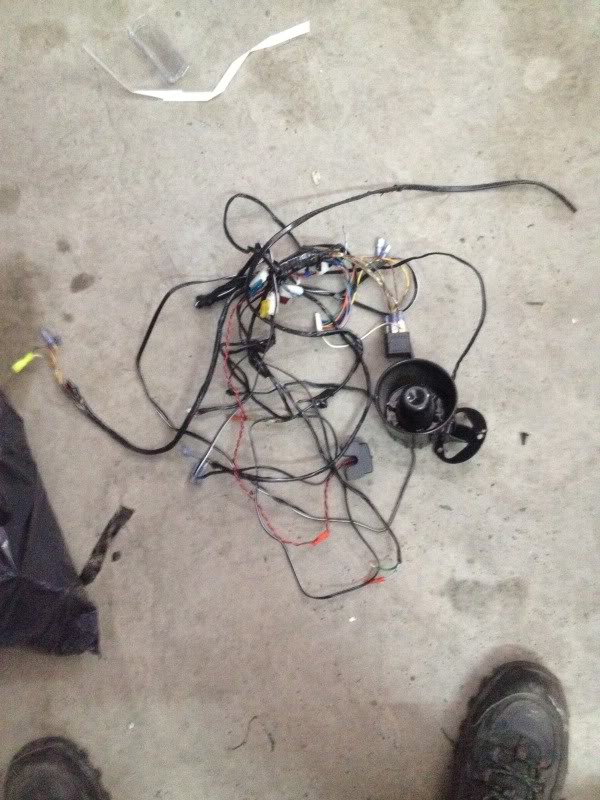
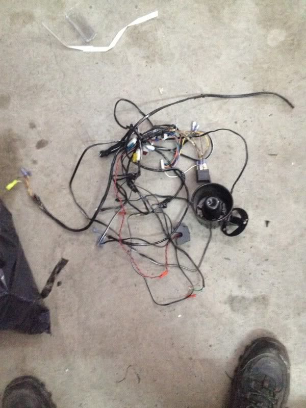
Unfortunately this won't be the most interesting post, its all wiring. I spent most of the day tearing the interior of the car apart to remove the autopage terrorist alarm system from the car that the original owner had put on. The installer did not make it easy on me at all on this, there were pieces EVERYWHERE.
but at the end of the day I got the rats nest of crap out.
So on to actual progress...
The most daunting part of this swap for people is likely the wiring. I'm going to try and point out as much of it as clearly as I can for whomever may want to try this later. Note that this is an 08 so plugs, wire colors, and some components may have changed throughout the years.
First this I did was the cooling fans. Nissan uses the IPDM ecu to turn on the factory fans by supplying a ground to the relays. The GM harness and ECU I have suppliers a 12V, and a single 30 amp line at that. You're left with two wiring choices here, you can either add a second 12v 30A circuit from the GM side, or wire into the IPDM and use the Z relays and wiring which is already present. I chose to use the Z relays which meant I had to make my 30A 12V line turn into a ground. I removed the 12v source to the GM relay and put it to ground instead and then ran that to the 3 Z fan relays.
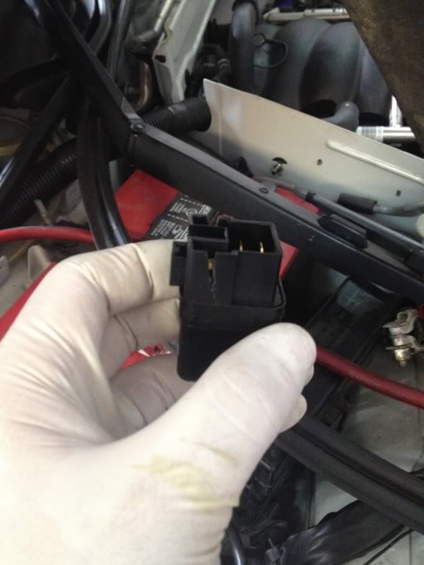
Since my ECU can only handle single speed control, I have to make all 3 Z Relays come on when the GM ecu commands the fans on. In the IPDM the relay in my hand is what your looking for, all 3 are removed in this photo.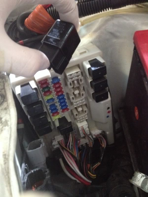
to run There were a couple options to get the switched ground to these but since the lines from the IPDM ecu to the relays did not provide adequate room to splice into, I had to get creative. I made a small cut into the ground side of each relay and then ran a wire to the contact and soldered it to the IPDM side contact. On the 08 years the ground side is on the right as you look at it.
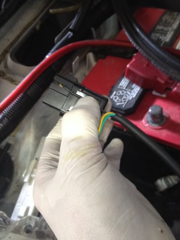
Here is the cut in the relay
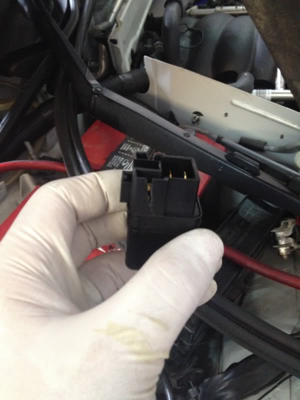
What the wire will look like after its run through the cut

And then what it looks like when its soldered to the contact, you can see the 2 below are done, the top one is left open so you can see where its soldered to.
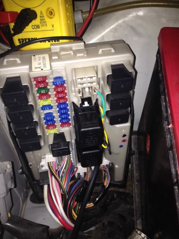
When the GM ecu turns the fans on now, it will send both stock fans into full high, its not the perfect solution, but will work up until I get a fan controller.
The next post I'll work out the starter solenoid wiring and charging system.
Unfortunately this won't be the most interesting post, its all wiring. I spent most of the day tearing the interior of the car apart to remove the autopage terrorist alarm system from the car that the original owner had put on. The installer did not make it easy on me at all on this, there were pieces EVERYWHERE.
but at the end of the day I got the rats nest of crap out.

So on to actual progress...
The most daunting part of this swap for people is likely the wiring. I'm going to try and point out as much of it as clearly as I can for whomever may want to try this later. Note that this is an 08 so plugs, wire colors, and some components may have changed throughout the years.
First this I did was the cooling fans. Nissan uses the IPDM ecu to turn on the factory fans by supplying a ground to the relays. The GM harness and ECU I have suppliers a 12V, and a single 30 amp line at that. You're left with two wiring choices here, you can either add a second 12v 30A circuit from the GM side, or wire into the IPDM and use the Z relays and wiring which is already present. I chose to use the Z relays which meant I had to make my 30A 12V line turn into a ground. I removed the 12v source to the GM relay and put it to ground instead and then ran that to the 3 Z fan relays.
Since my ECU can only handle single speed control, I have to make all 3 Z Relays come on when the GM ecu commands the fans on. In the IPDM the relay in my hand is what your looking for, all 3 are removed in this photo.

to run There were a couple options to get the switched ground to these but since the lines from the IPDM ecu to the relays did not provide adequate room to splice into, I had to get creative. I made a small cut into the ground side of each relay and then ran a wire to the contact and soldered it to the IPDM side contact. On the 08 years the ground side is on the right as you look at it.
Here is the cut in the relay

What the wire will look like after its run through the cut

And then what it looks like when its soldered to the contact, you can see the 2 below are done, the top one is left open so you can see where its soldered to.

When the GM ecu turns the fans on now, it will send both stock fans into full high, its not the perfect solution, but will work up until I get a fan controller.
The next post I'll work out the starter solenoid wiring and charging system.

New Member
Joined: Jan 2011
Posts: 190
Likes: 4
From: Northern FL
I finally got some time to work on the car, my weekend has been made.
Unfortunately this won't be the most interesting post, its all wiring. I spent most of the day tearing the interior of the car apart to remove the autopage terrorist alarm system from the car that the original owner had put on. The installer did not make it easy on me at all on this, there were pieces EVERYWHERE.
but at the end of the day I got the rats nest of crap out.
So on to actual progress...
The most daunting part of this swap for people is likely the wiring. I'm going to try and point out as much of it as clearly as I can for whomever may want to try this later. Note that this is an 08 so plugs, wire colors, and some components may have changed throughout the years.
First this I did was the cooling fans. Nissan uses the IPDM ecu to turn on the factory fans by supplying a ground to the relays. The GM harness and ECU I have suppliers a 12V, and a single 30 amp line at that. You're left with two wiring choices here, you can either add a second 12v 30A circuit from the GM side, or wire into the IPDM and use the Z relays and wiring which is already present. I chose to use the Z relays which meant I had to make my 30A 12V line turn into a ground. I removed the 12v source to the GM relay and put it to ground instead and then ran that to the 3 Z fan relays.
Since my ECU can only handle single speed control, I have to make all 3 Z Relays come on when the GM ecu commands the fans on. In the IPDM the relay in my hand is what your looking for, all 3 are removed in this photo.
to run There were a couple options to get the switched ground to these but since the lines from the IPDM ecu to the relays did not provide adequate room to splice into, I had to get creative. I made a small cut into the ground side of each relay and then ran a wire to the contact and soldered it to the IPDM side contact. On the 08 years the ground side is on the right as you look at it.
Here is the cut in the relay
What the wire will look like after its run through the cut
And then what it looks like when its soldered to the contact, you can see the 2 below are done, the top one is left open so you can see where its soldered to.

When the GM ecu turns the fans on now, it will send both stock fans into full high, its not the perfect solution, but will work up until I get a fan controller.
The next post I'll work out the starter solenoid wiring and charging system.
Unfortunately this won't be the most interesting post, its all wiring. I spent most of the day tearing the interior of the car apart to remove the autopage terrorist alarm system from the car that the original owner had put on. The installer did not make it easy on me at all on this, there were pieces EVERYWHERE.
but at the end of the day I got the rats nest of crap out.
So on to actual progress...
The most daunting part of this swap for people is likely the wiring. I'm going to try and point out as much of it as clearly as I can for whomever may want to try this later. Note that this is an 08 so plugs, wire colors, and some components may have changed throughout the years.
First this I did was the cooling fans. Nissan uses the IPDM ecu to turn on the factory fans by supplying a ground to the relays. The GM harness and ECU I have suppliers a 12V, and a single 30 amp line at that. You're left with two wiring choices here, you can either add a second 12v 30A circuit from the GM side, or wire into the IPDM and use the Z relays and wiring which is already present. I chose to use the Z relays which meant I had to make my 30A 12V line turn into a ground. I removed the 12v source to the GM relay and put it to ground instead and then ran that to the 3 Z fan relays.
Since my ECU can only handle single speed control, I have to make all 3 Z Relays come on when the GM ecu commands the fans on. In the IPDM the relay in my hand is what your looking for, all 3 are removed in this photo.
to run There were a couple options to get the switched ground to these but since the lines from the IPDM ecu to the relays did not provide adequate room to splice into, I had to get creative. I made a small cut into the ground side of each relay and then ran a wire to the contact and soldered it to the IPDM side contact. On the 08 years the ground side is on the right as you look at it.
Here is the cut in the relay
What the wire will look like after its run through the cut
And then what it looks like when its soldered to the contact, you can see the 2 below are done, the top one is left open so you can see where its soldered to.
When the GM ecu turns the fans on now, it will send both stock fans into full high, its not the perfect solution, but will work up until I get a fan controller.
The next post I'll work out the starter solenoid wiring and charging system.

It is already done and really was not too invasive. It was either run 2 new fused lines like you said or just run the ground wire through a relay, I think both are actually about the same amount of work.

This weekend was spent finishing a majority of the wiring. The charging system was done and that was as simple as taking a 6 gauge wire and running it from the post on the back of the alternator to the post on the fuse/relay panel.
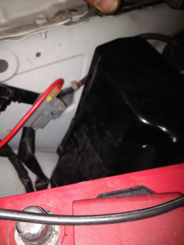
After that was the starter. Run a large gauge wire of the pos batter terminal to the heavy gauge pos post on the starter. After that run an appropriate sized wire to the starter solenoid from the IPDM or the connector next to it. I used a 10 gauge for the solenoid, crimp on a female spade connector to one end and a terminal lug to the other. Connect the spade connector here:
After that the wiring minus the gauges is done. So I moved onto the intake. Its based off a Camaro SS K&N unit, I just had to cut about 1 and a half inches of length off of it.
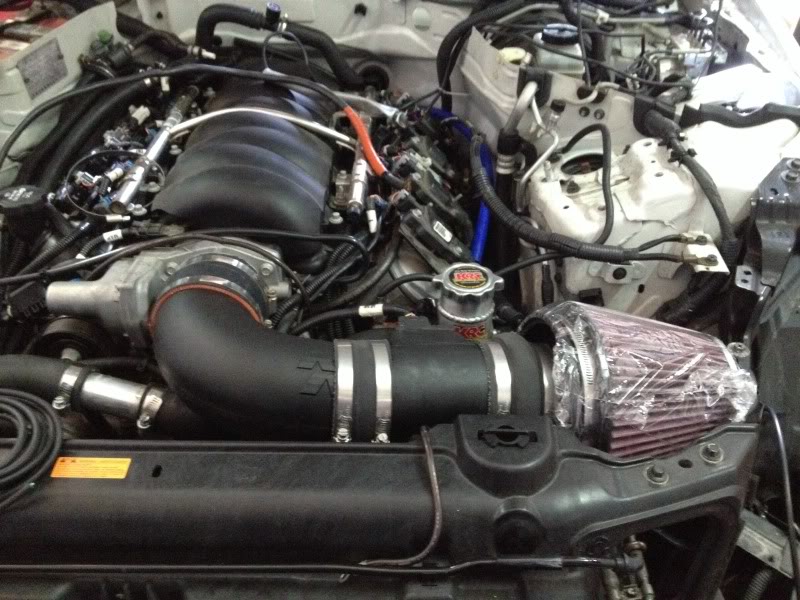
I'll start putting the front end back together next and hopefully the differential arrives from Z1 performance soon so I can get the differential back in. After that its simply welding up the exhaust and it will be street worthy and CARB legal.
After that was the starter. Run a large gauge wire of the pos batter terminal to the heavy gauge pos post on the starter. After that run an appropriate sized wire to the starter solenoid from the IPDM or the connector next to it. I used a 10 gauge for the solenoid, crimp on a female spade connector to one end and a terminal lug to the other. Connect the spade connector here:

After that the wiring minus the gauges is done. So I moved onto the intake. Its based off a Camaro SS K&N unit, I just had to cut about 1 and a half inches of length off of it.

I'll start putting the front end back together next and hopefully the differential arrives from Z1 performance soon so I can get the differential back in. After that its simply welding up the exhaust and it will be street worthy and CARB legal.

This pump is flow adjustable via a swappable flow restrictor valve. On the track I like to have very little steering assist, on the street and especially in parking lots I prefer a wee bit more.
I would be pretty excited if we could get an autobahn LSz video!
I might have missed it but what did you do with the diff?
update?
id also like to suggest to change the differential and subframe bushings, with that new added power I think the old silicone filled bushings might not stand up for long, when they fail the silicone comes out and makes the car feel like it has no bushings.
id also like to suggest to change the differential and subframe bushings, with that new added power I think the old silicone filled bushings might not stand up for long, when they fail the silicone comes out and makes the car feel like it has no bushings.
Last edited by 350zsunshinefl; Jun 21, 2014 at 02:05 PM.
Check post 11, the bushings have already been done. As for the diff itself, I'm awaiting the cusco unit I purchased from Z1 auto.
I've gotten some work done I just havent had time to snap pictures of it all. Whats done so far:
-finished the coolant system
-fuel pump replaced
- Drivers side Cat has been hacked up and welded so it mates with the exhaust using a v-band clamp.
-wiring and gauges are still in progress.
I've gotten some work done I just havent had time to snap pictures of it all. Whats done so far:
-finished the coolant system
-fuel pump replaced
- Drivers side Cat has been hacked up and welded so it mates with the exhaust using a v-band clamp.
-wiring and gauges are still in progress.
