When you click on links to various merchants on this site and make a purchase, this can result in this site earning a commission. Affiliate programs and affiliations include, but are not limited to, the eBay Partner Network.
Oh and I also started making the structure that is going to support the radiator and intercooler. Still loads more to do on it but here's what I've got so far
Got the upper radiator support and front bumper mounting points made over the last couple of days, as well as getting the intercooler core mounted. Although think we need to add some more strength to the front bumper support as the weight of the bumper makes it flex a bit.
EDIT:
Made some new mounting tabs for the rad/bumper frame to try and help stop it flexing (didn't help that much, but at least they look a bit nicer now lol)
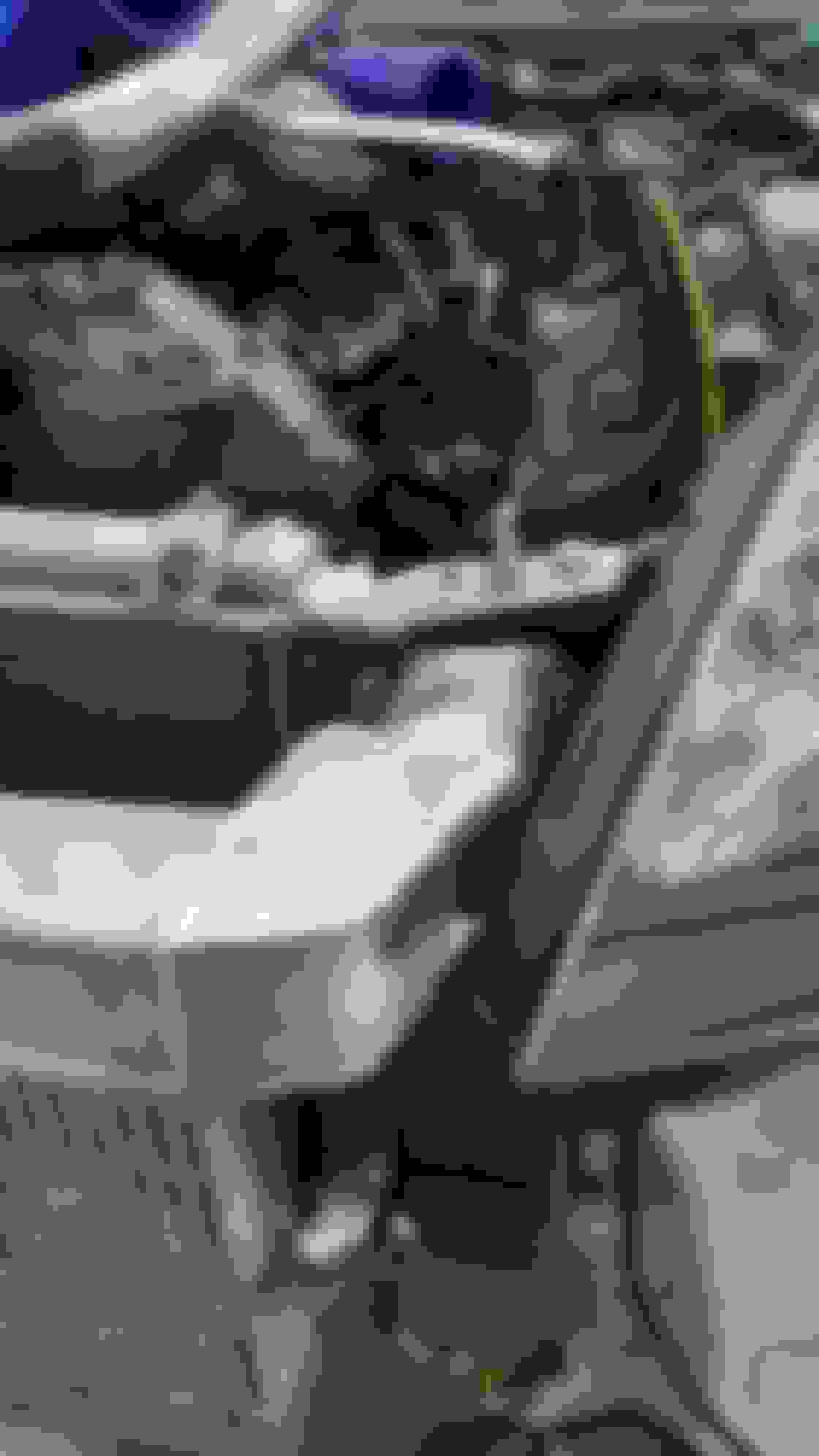
Started making up the intercooler end tanks this week. At first the aluminium welding went REALLY badly, and I thought maybe I was just out of practice as I'd been doing steel so much recently. But it turned out the welding torch had a leak, and once I got a new torch it was a million times easier. Unfortunately by that point I'd already tried to do a lot of the welding on the top end tank with the broken torch and made quite a mess, so I ended up going over it again with the new torch and trying to tidy it up (which is why you see the really big and slightly messy welding beads on one edge in the pictures).
Yes the intercooler is huge... I kind of regret getting the core made in that size as its proving very difficult to make the ends of the tanks actually fit, but what's done is done and that's what I've got to work with.
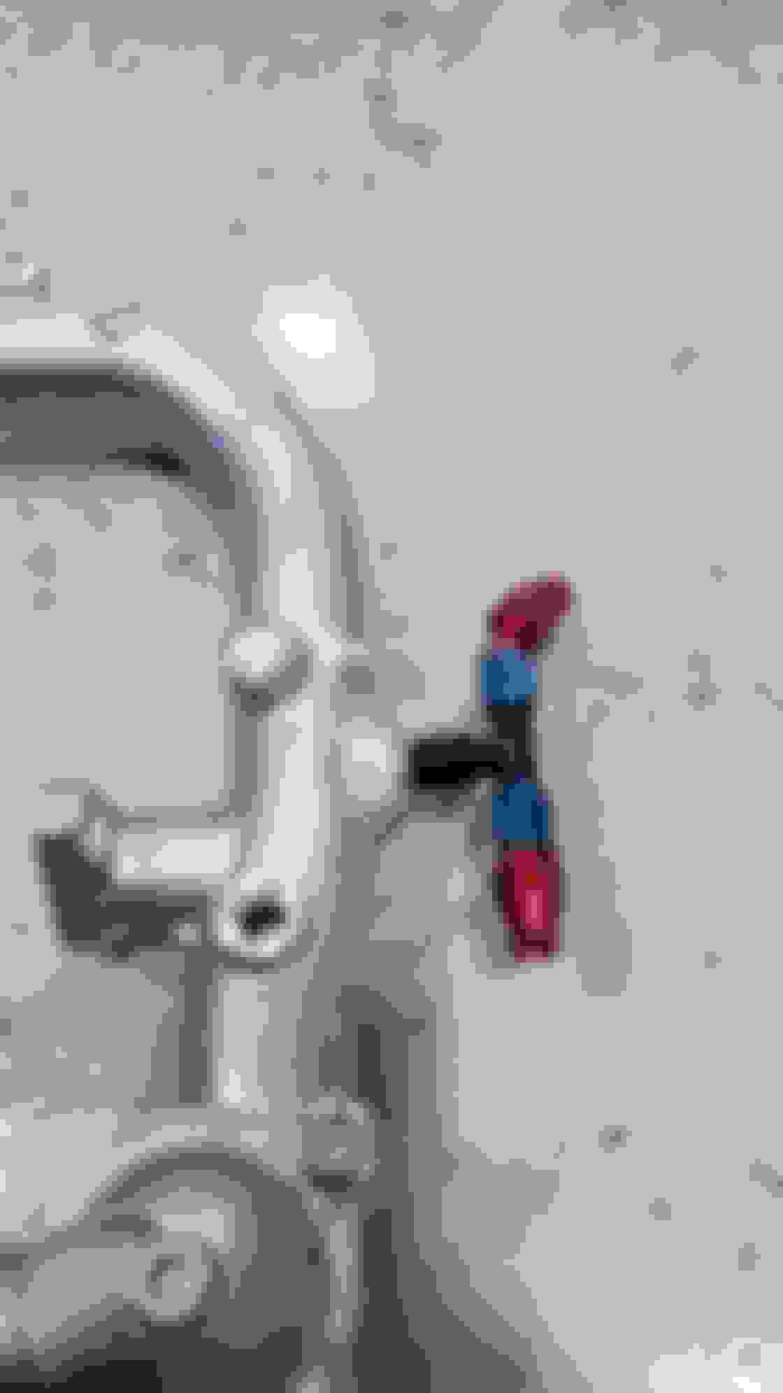
One other thing I got done a couple of days ago was making up the new oil cooler lines:
My God man, those welds are hideous! They'll haunt my dreams for days. Burned my retinas!
I've no idea if you're joking, cos some of them really were horrendous when I was using the broken torch and even though I tried to cover them up they still don't look great. But I tried to keep them out of the photos as much as I could haha Here's what some of it looked like with the broken torch:
Oh, I'm serious. Those welds make me want to hang myself. They make me angry. After I saw the pics, I ran outside and kicked my neighbors dog straight in the junk. Now my neighbors dog is angry.
I'm kidding.
Got the top end tank pretty much finished today... I know the outlet is pretty weird but it was the only way I could think of to make the outlet actually end up in the right place whilst avoiding hitting the headlights or radiator. Original plan was to just have a 90 degree bend come off the end tank but due to the intercooler being so large, there was no way that would fit when you consider the piping coming out of the intercooler needs to be about 3 inch diameter.
The headlights are the main reason for the weird shape. Even after all this, there's still only about 2mm gap between end tank and headlight at one point.
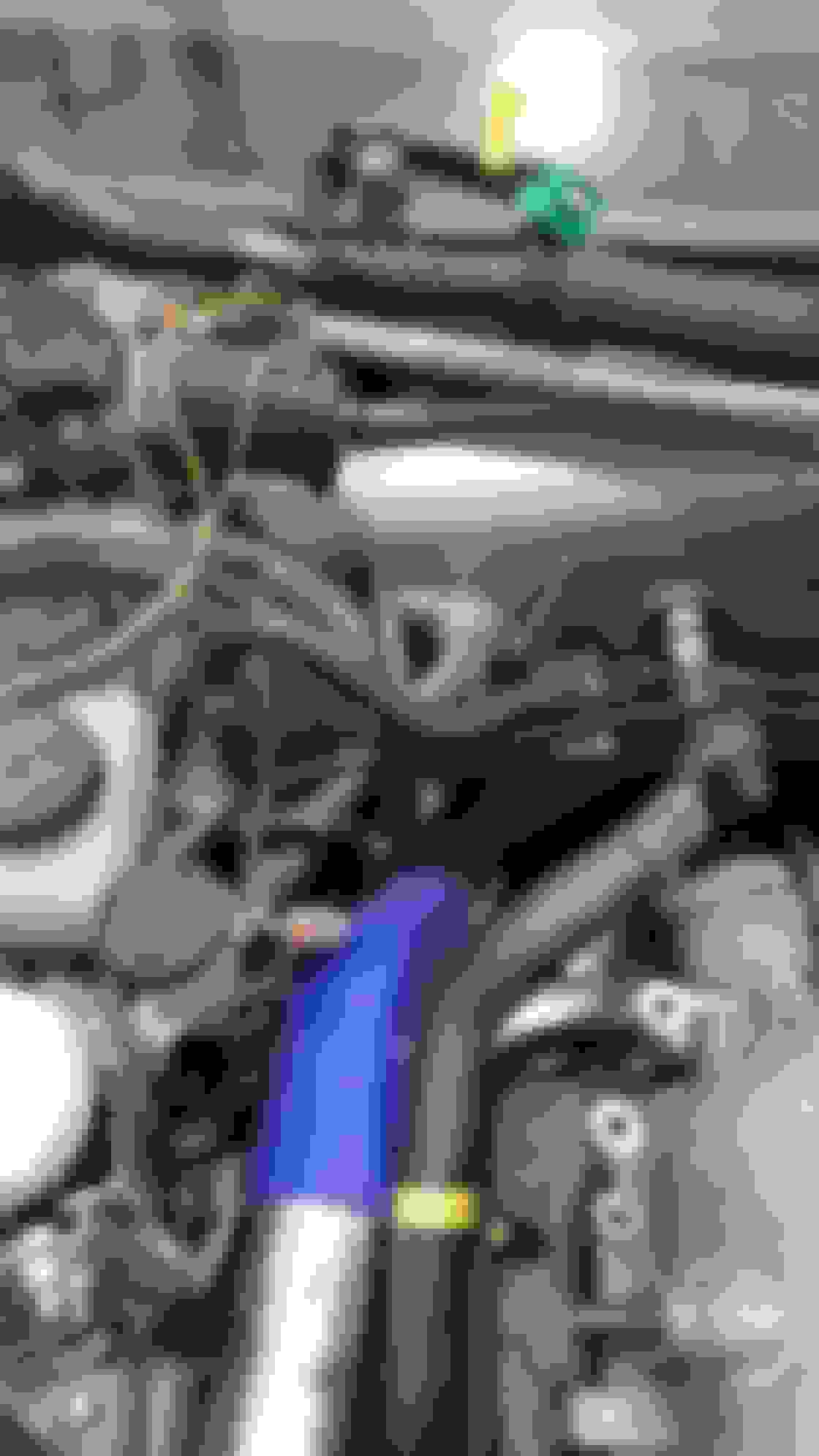
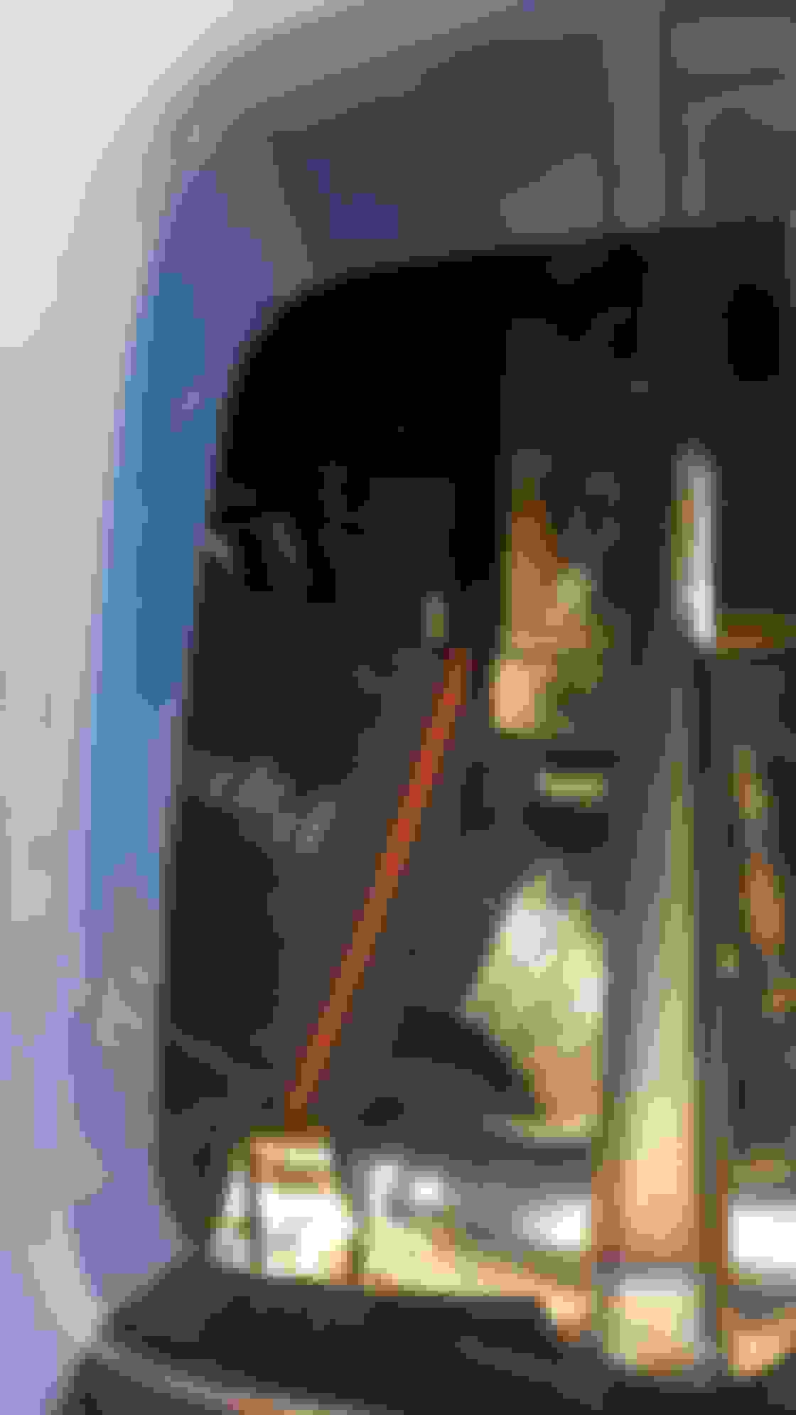
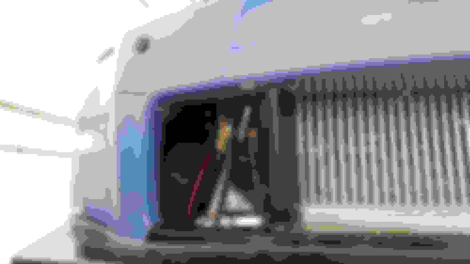
We also got all the intake piping in place but not fully welded up yet. This includes the very awkward pipe that needed to go from the turbo to the air filter at the front of the car (which means avoiding the steering column and trying to keep it from getting too close to the exhaust manifold).
The runners are all 1.25 inch schedule 10, which in reality is more like 1.5 inch diameter and is 2.7mm wall thickness. I was originally going to go for 1.5 inch schedule 10 but a motorsports fab shop near me said that's overkill for the power I'm aiming for and mentioned they'd had cars running up to 700 bhp on 1.25 inch schedule 10 runners.
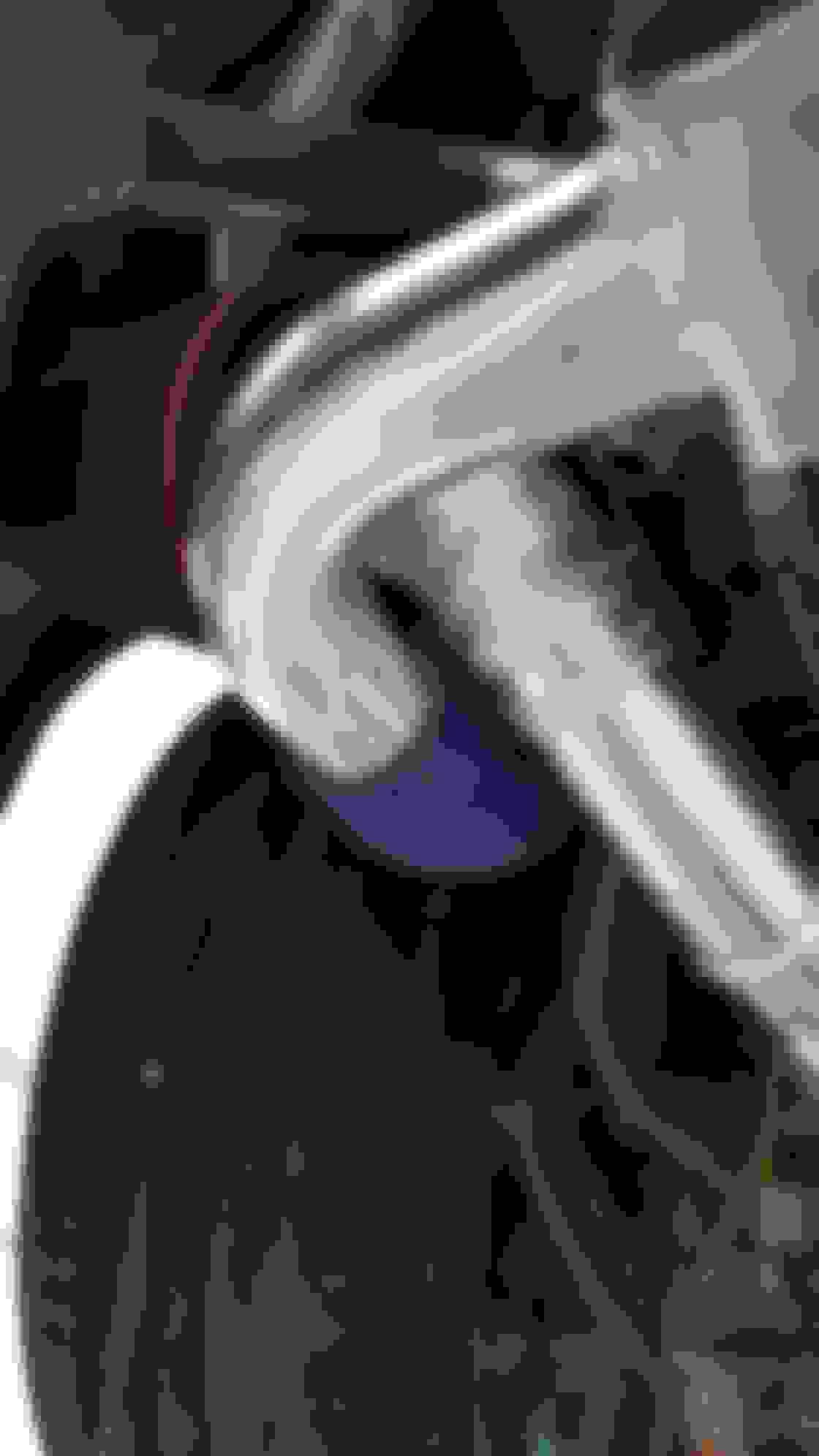
Welded AN fitting onto the coolant pipe that comes off the back of the engine (its shiny and new because I got it for the pathfinder mod, but have since discovered that mod is completely useless unless you're willing to drill the inside of the engine block - more info here: https://my350z.com/forum/engine-and-...inder-mod.html)
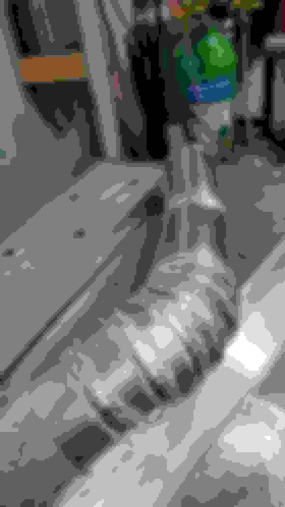
Also made the oil drain sump for one of the turbos that the scavenger pump will pull the oil from:
The weird shaped inlet is just to allow access to the bolts that attach it to the turbo whilst also keeping the sump/tank high enough so we don't have any ground clearance issues
Slight delay as I managed to set fire to the car yesterday whilst doing some mig welding underneath
It was my own stupid mistake for thinking I'd got rid of all the insulation stuff on the other side of where I was welding... apparently not. Took me 3 fire extinguishers to put it out and I honestly thought the whole car was going up in flames at one point as flames were flying out of the engine bay through the gap where the heater fan draws air through, and a lot of flames and smoke were coming up on the inside of the windscreen as well. Luckily the damage seems to be limited to the Link ECU O2 sensor wires, the heater fan unit itself and some of its wiring, and some small wires I'd added myself for oil cooler fan etc. So yeah all the fire damage seems fairly easily repairable, but it just depends how much damage the fire extinguisher powder and foam did to electrical terminals etc (once the powder mixes with any moisture, it gets very corrosive on metal). So yeah, we'll add that to the extremely long list of potential issues when I first start the car up once this is all complete.
I've been meaning to ask you ... I'm starting headers myself...is there any words of wisdom you can offer on the order of welding you did?
Meaning - I'm tacking everything up now and once things are where they need to be should I start by removing each runner from the exhaust flange and welding each series of pipe 100% and then welding them back to the flange? I dont want to be forced to cut & re-weld because I did something out of order...any thoughts would be appreciated!
I'll be honest no matter what you do its a pain in the *** because stainless steel warps so much lol I tried to make sure I wouldn't have any issues by welding as much of the runners as possible whilst they were all tacked together and in their correct place, then cut them off and finished the bits I couldn't access when they were together. But on both sides I found it didn't all fit back together perfectly once I'd done all the welding of each runner individually, so I ended up having to cut the ends off at least one runner on each side and make new pieces to bridge the new size/shaped gaps between the end of the runner and the collector.
Dunno if you saw my videos of me making mine but it might help a bit:
I guess you might be best off just making 90% of each runner and leaving the very last bits that connect to the collector, welding as much of it as possible like that, then breaking them off from the exhaust port flange and finishing the welding of each one. Then put them back together and make the final part that connects them to the collector. I suppose the only problem with that would be if they warped so much that there was no way you could join all 3 of them to the collector.
I spent ages watching other people make them and it seems like most people don't seem to have as many space constraints as I had to deal with so they just kind of let the collector sit wherever is easiest to make the runners meet... but I felt like on the drivers side I had to have the collector in a very specific spot to make it fit through the steering column etc.
At the end of the day though, I've very little experience making anything like this and not much experience with welding in general, so if I can do it then I'm sure you'll be fine lol