
Interior LED Conversion

 07-04-2009, 02:05 AM
#42
Registered User
iTrader: (4)

Join Date: Apr 2008
Location: New Orleans
Posts: 2,157
Likes: 0
Received 0 Likes
on
0 Posts
Im still waiting for my gauges...hopefully they will ship soon seeing as I didnt get a personal one...
07-09-2009, 03:48 PM
#43
Registered User
iTrader: (4)
Join Date: Apr 2008
Location: New Orleans
Posts: 2,157
Likes: 0
Received 0 Likes
on
0 Posts
just got finished doing my center console but can someone tell me how to fix the needles? they wont read the right oil temp and volts. i hopethis **** doesnt happen when i change my reg gauges
07-09-2009, 09:10 PM
#44

I assume you took pics of the needle positions before you changed your gauge faces.
Here's how I did mine.
- Plug in the cluster without mounting it. There is enough slack in the cable for it to reach up and over the top of the center console. You can set the cluster up there without fastening it in.
- The front plastic lens piece should be off. You should just have the gauge faces on and the LCD plugged in and the needles OFF.
- Start the car. This will cause the needle stems to go their normal position.
- Using your reference pictures, place the needles on the stems, partly. Do not press down on them so they click. Reason is to allow for easy adjustment if needed. Sometimes when I put a needle on and pull my hand away it's not quite exact so I don't snap them in until it's right.
- Once you have your needles right, carefully press down on the center and they will click onto the stems and should be in the right position.
- Turn off the car, turn it back on again to confirm then turn it off.
- Disconnect the cluster, re-assemble and re-install.

 07-10-2009, 10:50 PM
#52
Registered User
iTrader: (5)

Join Date: Jul 2008
Location: Milwaukee
Posts: 97
Likes: 0
Received 0 Likes
on
0 Posts
Yeah the outside buttons are for the heated seat and the middle one is for the traction control, which is normally located by the gas door release. I ran across a thread where the member moved the button to where I placed it. Much easier to turn it off when I want to have a little fun with her.
07-17-2009, 07:20 PM
#53
Section 2B AC Controls for 2006 - 2008
Use the procedure from Section 2 to remove the AC Controls housing.
Remove the 4 screws from the back of the housing and remove the back.
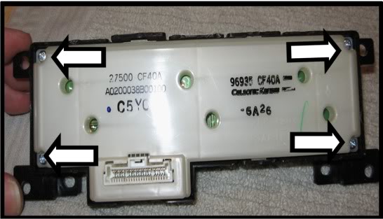
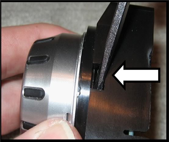
Insert a small flat blade screwdriver into the notch of a **** as shown below and twist the blade to begin removing the ****. Once that part of the **** pops up, turn the **** a quarter turn and pry that section up. Continue turning and prying until the **** has been pried loose all the way around.
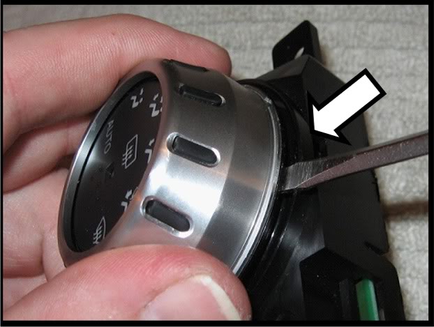
If the **** is still clipped to the control box, use the same flat blade as shown below to pry it off at different spots around the edge. Once loose, pull the **** off. The **** will be in two pieces, the inner pushbutton part with the graphic indicators and the outer silver piece.
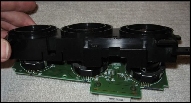
Remove all three outer ***** and pushbutton pieces and then pull the black housing off of the circuit board.
NOTE: It is recommended that you work on one dial at a time. This way you can check your work as you go.
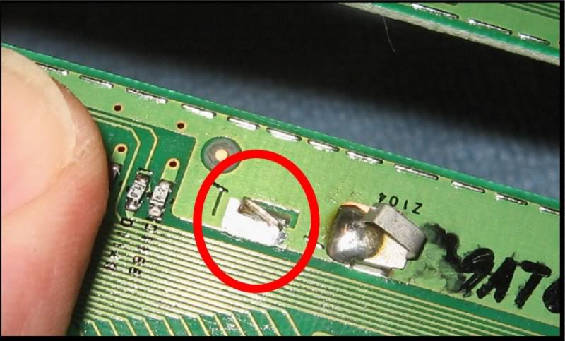
Desolder the two legs on the back of the circuit board circled in the picture below. If you have trouble getting the solder out, a shortcut is to place a small flat blade screwdriver between the surface of the board and the bottom of the dial assembly, heat up one leg until the solder liquifies and then carefully use the screwdriver as a lever to life the dial assembly until the leg clears the hole.

Turn the board over and gently lift the dial up, and back so that the contract legs along the base bend and the dial assembly is oriented 90 degrees from the board.

Replace the LEDs circled in the picture below. You can use either 0603 or 0805 type LEDs to replace the small LEDs and PLCC-2 to replace the larger square ones. Note the orientation of the LEDs on the board. They must be replaced the same way. The contacts for all have a line silkscreened onto the board at the cathode (negative) end.
Take the board back to the car, plug it into the ribbon cable and turn on the headlights to confirm the LEDs are working.
You may have to start the car to check the functioning of the larger LED that works with the pushbutton.
This next step is for replacing the pointer LED. This part is fairly intricate so if you don't mind the amber colored pointer, repeat what you just did on the other two dials and move to the next part of this section.
Use a small flat blade screwdriver to pry up the fingers of the metal retainer that holds the dial pieces together and then bend them up so they clear the bottom edge of the dial assembly.
Do not bend the contact legs that you just desoldered, leave them straight.
While doing this, be sure to hold the dial assembly as still as you can to avoid stressing the legs at the base that are still soldered to the board.

Remove the metal retaining ring.

Pull the top half of the dial off, turn it upside down and set the board off to the side. It is recommended that you cover the bottom half of the switch to prevent dust, hairs, fibers, debris, etc from settling onto the contacts inside.

NOTE – The steps that follow for removing and replacing the LED are from the author’s experience. It is highly recommended that you read through them first, examine the piece and consider optional approaches. The author does not claim this method to be the best or only method. The important thing is to understand that the small contact arms that touch the LED contacts are very easy to bend and can be difficult to put back into a shape that will result in proper operation.
Using the tip of an Xacto knife blade or the corner of a razor blade, carefully shave off the tops of the plastic pegs circled below. Try to leave some of the peg in place to ease re-assembly. The red circled pegs hold down one set of the contacts and the green hold down the other. It is recommended that you remove one contact at a time.

Below is a picture of the dial with the contacts removed and the LED fully exposed. The polarity of the LED is the negative (cathode) contact is to the right in this orientation and the positive is to the left.

Use the end of a paper clip to push the LED out of its seat from the other side of the dial as shown in the picture below.
After removing the LED, also remove any debris, pieces of plastic, etc. but DO NOT CLEAN OFF ANY OF THE LUBRICANT OIL.
Tin the contacts of the new LED with a very small amount of solder.
Using a pair of tweezers, place the new LED into the seat. NOTE – the back of the LED should be flush with the surface like the original. You may need to press lightly on the back of the LED to get it to click into place.
NOTE – if the contact assemblies don't lay flat, don’t worry about it. The gluing process will fix that. Having a second small “tool” to work with makes the following steps easier to accomplish.
Place one set of contacts close to its original location and orientation. NOTE - You will NOT be applying any glue to the contact arms that touch the LED contacts. Only apply glue to the areas of the contacts that were held in place by the plastic heads that were shaved off.
Hold the far end of one of the contact assemblies in place using a second small tool. Use a sewing needle or the tip of a paper clip, to apply a small amount of glue to the area where the contact and the peg mate up. Be sure that the glue covers the outside edges of the contact.
Let the glue dry while holding the contact in place with the second small tool. Glue the next fastening point of the contact assembly until thall the points are glued.
Use a second small tool to lightly hold the contact arms down so they touch the LED contact.
Barely touch your soldering iron to the top of the contact arms so they sink into the solder on the tinned LED contact. Watch out that you don't melt plastic in the area.Remove the soldering iron, wait a second or two for the solder to cool, remove the small tool and confirm that the contact arms are constantly touching the LED contact.
Repeat the process for the other contact assembly.
Some of the contact arms that run along the board inside the dial may have become bent. Inspect them and bend them back into the right orientation with a small tool if needed.
Remove any hairs, fibers, debris, etc and place it onto the lower half.

Replace the retainer ring, bend the arms back into their original position. Keep the dial assembly as still to avoid stressing the legs still soldered into the board.

Test your work in the car. Turn the dial back and forth and confirm that the LED stays lit all the time.
Ensure that the dial assembly is straight and level relative to the board.
Re-solder the legs to the board.
Repeat the process for the other two dials.
Remove the amber colored pointerss by pushing the bottom up and out from inside the trim ring.

Use a sharp blade to cut into the amber coating at the lower edge and peel it off. The coating at the “heel” (left end in these pics) has to be scraped off as it will not peel off.

Re-insert the pointers into trim rings and press into place.

Rotate all the dials counter-clockwise as far as they will go and snap the outer trim rings on.
Press the center pushbutton sections in. NOTE - if a center does not go in easily, the dial may not be level with the board.

Re-fasten the back of the control module with the 4 screws, snap the module back into the lower finisher, connect the ribbon cable and snap the lower finisher into the center console.
Use the procedure from Section 2 to remove the AC Controls housing.
Remove the 4 screws from the back of the housing and remove the back.
Insert a small flat blade screwdriver into the notch of a **** as shown below and twist the blade to begin removing the ****. Once that part of the **** pops up, turn the **** a quarter turn and pry that section up. Continue turning and prying until the **** has been pried loose all the way around.
If the **** is still clipped to the control box, use the same flat blade as shown below to pry it off at different spots around the edge. Once loose, pull the **** off. The **** will be in two pieces, the inner pushbutton part with the graphic indicators and the outer silver piece.
Remove all three outer ***** and pushbutton pieces and then pull the black housing off of the circuit board.
NOTE: It is recommended that you work on one dial at a time. This way you can check your work as you go.
Desolder the two legs on the back of the circuit board circled in the picture below. If you have trouble getting the solder out, a shortcut is to place a small flat blade screwdriver between the surface of the board and the bottom of the dial assembly, heat up one leg until the solder liquifies and then carefully use the screwdriver as a lever to life the dial assembly until the leg clears the hole.
Turn the board over and gently lift the dial up, and back so that the contract legs along the base bend and the dial assembly is oriented 90 degrees from the board.
Replace the LEDs circled in the picture below. You can use either 0603 or 0805 type LEDs to replace the small LEDs and PLCC-2 to replace the larger square ones. Note the orientation of the LEDs on the board. They must be replaced the same way. The contacts for all have a line silkscreened onto the board at the cathode (negative) end.
Take the board back to the car, plug it into the ribbon cable and turn on the headlights to confirm the LEDs are working.
You may have to start the car to check the functioning of the larger LED that works with the pushbutton.
This next step is for replacing the pointer LED. This part is fairly intricate so if you don't mind the amber colored pointer, repeat what you just did on the other two dials and move to the next part of this section.
Use a small flat blade screwdriver to pry up the fingers of the metal retainer that holds the dial pieces together and then bend them up so they clear the bottom edge of the dial assembly.
Do not bend the contact legs that you just desoldered, leave them straight.
While doing this, be sure to hold the dial assembly as still as you can to avoid stressing the legs at the base that are still soldered to the board.
Remove the metal retaining ring.
Pull the top half of the dial off, turn it upside down and set the board off to the side. It is recommended that you cover the bottom half of the switch to prevent dust, hairs, fibers, debris, etc from settling onto the contacts inside.
NOTE – The steps that follow for removing and replacing the LED are from the author’s experience. It is highly recommended that you read through them first, examine the piece and consider optional approaches. The author does not claim this method to be the best or only method. The important thing is to understand that the small contact arms that touch the LED contacts are very easy to bend and can be difficult to put back into a shape that will result in proper operation.
Using the tip of an Xacto knife blade or the corner of a razor blade, carefully shave off the tops of the plastic pegs circled below. Try to leave some of the peg in place to ease re-assembly. The red circled pegs hold down one set of the contacts and the green hold down the other. It is recommended that you remove one contact at a time.
Below is a picture of the dial with the contacts removed and the LED fully exposed. The polarity of the LED is the negative (cathode) contact is to the right in this orientation and the positive is to the left.
Use the end of a paper clip to push the LED out of its seat from the other side of the dial as shown in the picture below.
After removing the LED, also remove any debris, pieces of plastic, etc. but DO NOT CLEAN OFF ANY OF THE LUBRICANT OIL.
Tin the contacts of the new LED with a very small amount of solder.
Using a pair of tweezers, place the new LED into the seat. NOTE – the back of the LED should be flush with the surface like the original. You may need to press lightly on the back of the LED to get it to click into place.
NOTE – if the contact assemblies don't lay flat, don’t worry about it. The gluing process will fix that. Having a second small “tool” to work with makes the following steps easier to accomplish.
Place one set of contacts close to its original location and orientation. NOTE - You will NOT be applying any glue to the contact arms that touch the LED contacts. Only apply glue to the areas of the contacts that were held in place by the plastic heads that were shaved off.
Hold the far end of one of the contact assemblies in place using a second small tool. Use a sewing needle or the tip of a paper clip, to apply a small amount of glue to the area where the contact and the peg mate up. Be sure that the glue covers the outside edges of the contact.
Let the glue dry while holding the contact in place with the second small tool. Glue the next fastening point of the contact assembly until thall the points are glued.
Use a second small tool to lightly hold the contact arms down so they touch the LED contact.
Barely touch your soldering iron to the top of the contact arms so they sink into the solder on the tinned LED contact. Watch out that you don't melt plastic in the area.Remove the soldering iron, wait a second or two for the solder to cool, remove the small tool and confirm that the contact arms are constantly touching the LED contact.
Repeat the process for the other contact assembly.
Some of the contact arms that run along the board inside the dial may have become bent. Inspect them and bend them back into the right orientation with a small tool if needed.
Remove any hairs, fibers, debris, etc and place it onto the lower half.
Replace the retainer ring, bend the arms back into their original position. Keep the dial assembly as still to avoid stressing the legs still soldered into the board.
Test your work in the car. Turn the dial back and forth and confirm that the LED stays lit all the time.
Ensure that the dial assembly is straight and level relative to the board.
Re-solder the legs to the board.
Repeat the process for the other two dials.
Remove the amber colored pointerss by pushing the bottom up and out from inside the trim ring.
Use a sharp blade to cut into the amber coating at the lower edge and peel it off. The coating at the “heel” (left end in these pics) has to be scraped off as it will not peel off.
Re-insert the pointers into trim rings and press into place.
Rotate all the dials counter-clockwise as far as they will go and snap the outer trim rings on.
Press the center pushbutton sections in. NOTE - if a center does not go in easily, the dial may not be level with the board.
Re-fasten the back of the control module with the 4 screws, snap the module back into the lower finisher, connect the ribbon cable and snap the lower finisher into the center console.
Last edited by lbz; 11-06-2009 at 09:44 PM.
07-17-2009, 08:09 PM
#54
Section 4 The Stock (non-Bose) Radio
NOTE - The procedure for convering a Bose stock head unit should be fairly similar. I don't have the pics or experience with the Bose unit. There might be additional LEDs involved.
Use the AC Controls procedure to remove the lower finisher and set it aside.
Use the Center Console Gauges procedure to loosen and remove the center console
Remove the two screws on each side of the radio that secure it to the mounting bracket, pull the radio out and move it to your work area.
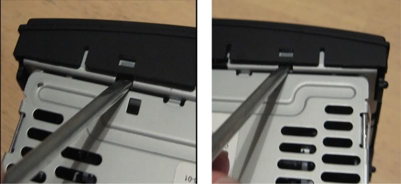
Use a small flat tip screw driver to pry the black plastic front face loose at each corner, top and bottom. After the tip is slightly in the hole, as shown below, pry up the tab just a little to unlock the black plastic and then leverage the blade against the metal enclosure by moving the base of the blade forward. The corner will come out just a bit and you will have to prevent it from snapping back into place when you do the other corners.
Once the face has been loosened from the metal enclosure, you should be able to pull it straight off.
Pull the volume **** straight off, should be able to do this with your fingers.
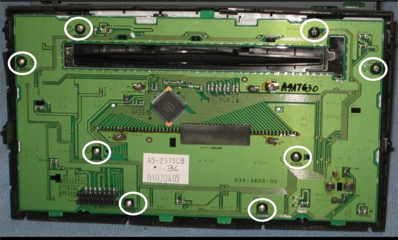
Turn the front plate face down and remove the 8 screws, circled below, that hold the circuit board to the back of the black plastic face and remove the circuit board.
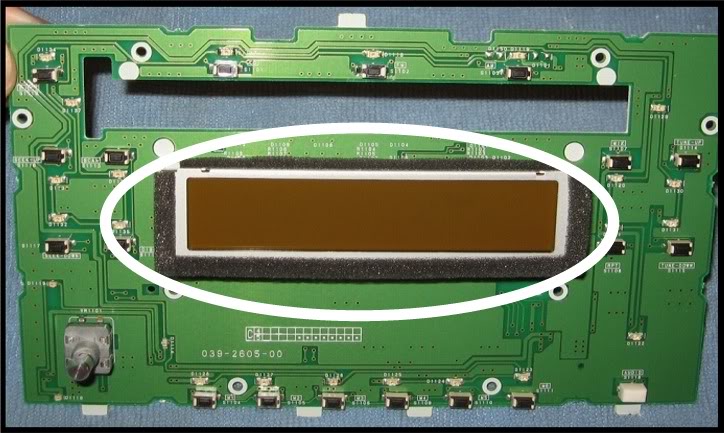
The next step is to remove the LCD housing., circled in the pic below.
Turn the circuit board over so that it is face down.
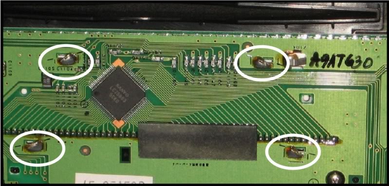
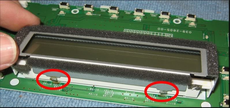
De-solder the four legs, circled below, that secure the metal housing to the circuit board. One leg has a small metal grounding contact over it that will have to be bent out of the way to access the leg. See the pic below which shows the contact already bent back, its next to the upper right solder joint.
Use small needle nose pliers to bend the bases of the legs straight so that they will go through the holes in the board.
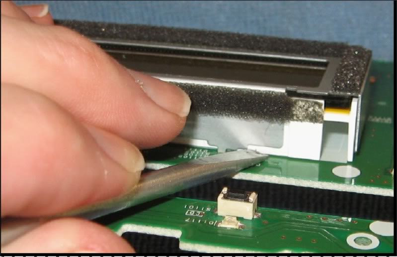
Use a small flat blade screw driver to pry each leg of the metal housing up through its hole in the board. Make sure you get the tip of the blade under the metal piece rather than the white plastic.
After all 4 corners are loose; pull up on the metal housing and remove it.
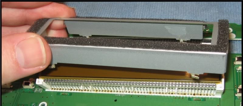
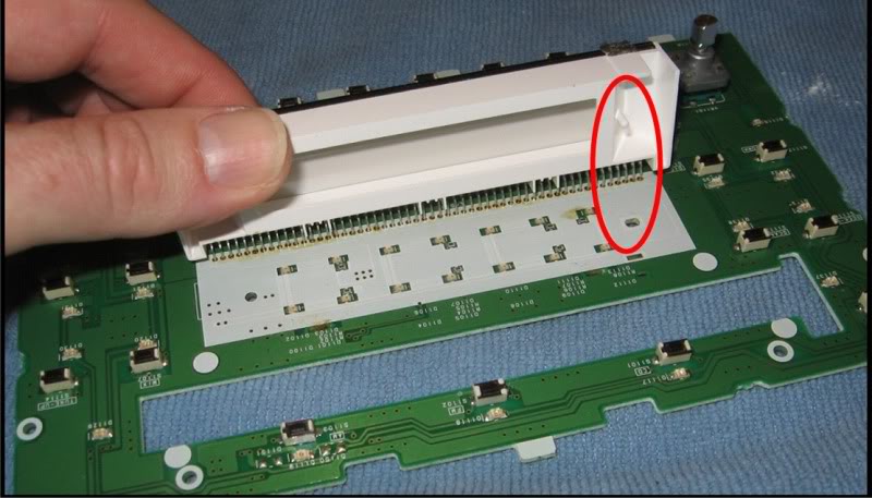
Orient the board so that the contact legs are on the far side and slowly and carefully push up and rotate the white plastic housing back so that the contact legs bend back as shown below. This will bend the contact legs but as long as these are not bent back and forth too much, they will not fatigue enough to crease or break.
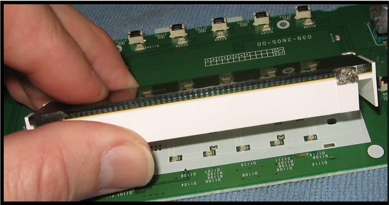
Use your thumbnail or fingernail to separate the white housing from the LCD.
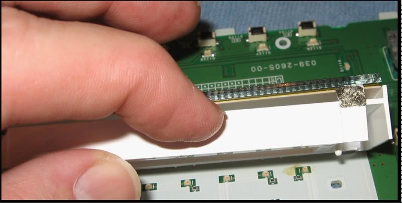
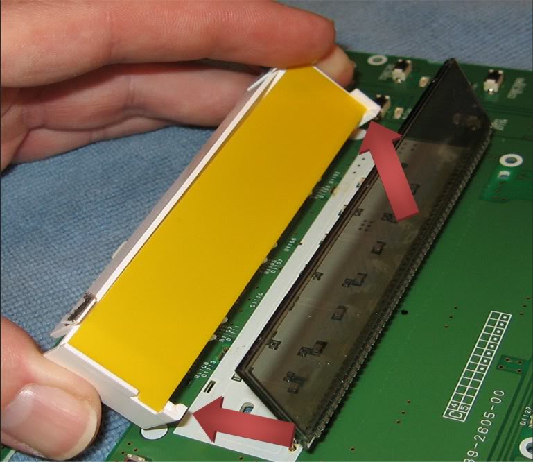
From the side of the white housing closest to the contact legs and the circuit board, wiggle the white housing loose and pull it out from under the LCD. You have to pull the housing down and then back to get the corners free. See the picture with the red arrows below.
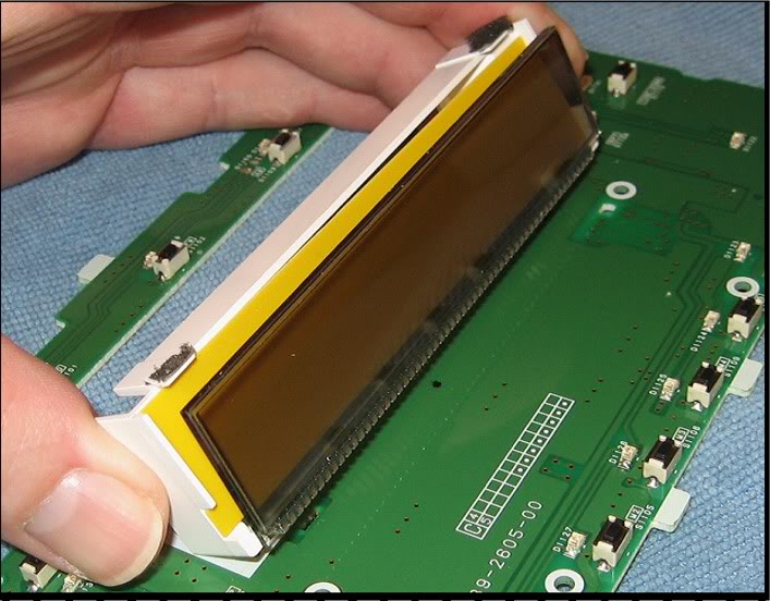
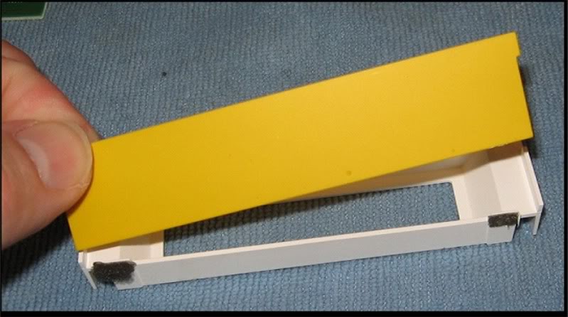
Remove the yellow diffuser from the white housing.
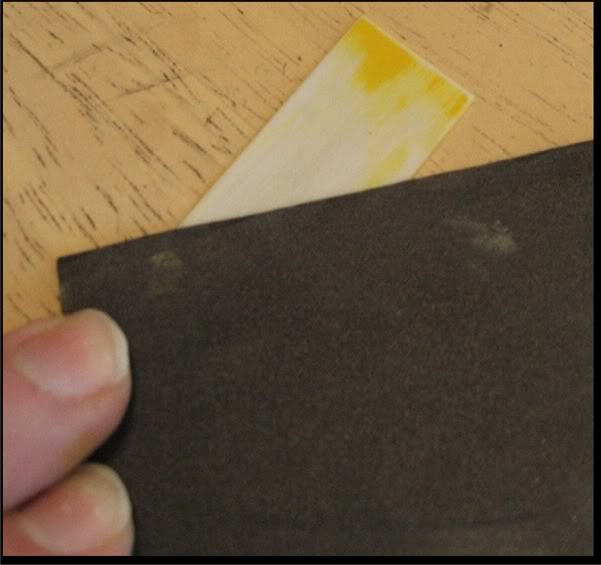
Wet sand the diffuser with 600 grit sandpaper to remove the yellow coating from the diffuser.
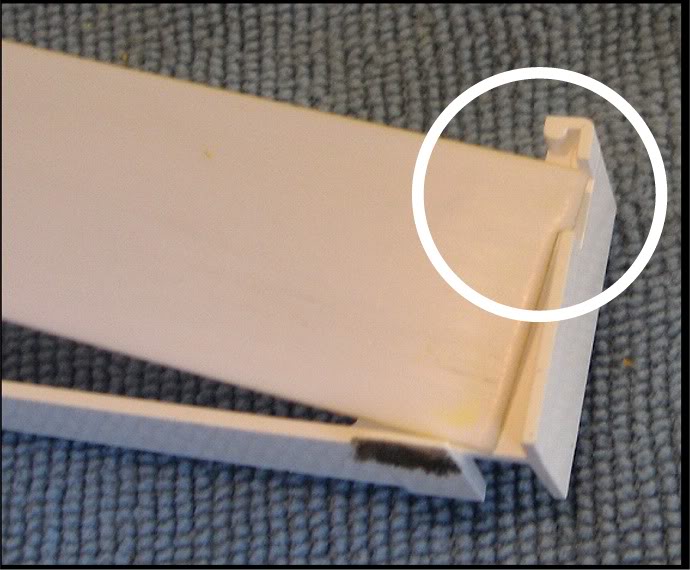
Place the diffuser back into the white housing. Be sure the tab goes into the proper location so the diffuser lays in flat.
Bend the LCD contact legs so the LCD is completely vertical. This will provide room for de-soldering the LEDs.
Remove and replace the type 0603 LEDs that are circled in red and the type 0805 LEDs that are circled in white. You can use different colors here if you want the LCD display and / or the volume **** to stand out.
Reinstall the white housing with the diffuser in place. Bring the housing in from under and behind so you get the corners around the edge of the LCD. The fins on the contacts side of the housing should slip between the contact legs.
Hold the white housing and the LCD together at both ends and carefully and slowly bring them together back down into position on the board. Note the two pegs in the bottom of the housing that should match up with the holes in the board. The left peg in this picture is obscured but the right side and the matched hole have been marked in red in the picture above.
Make sure the LCD is fully and evenly seated in the top of the housing. Note in the picture below that there is no gap between the LCD and the diffuser and the housing.
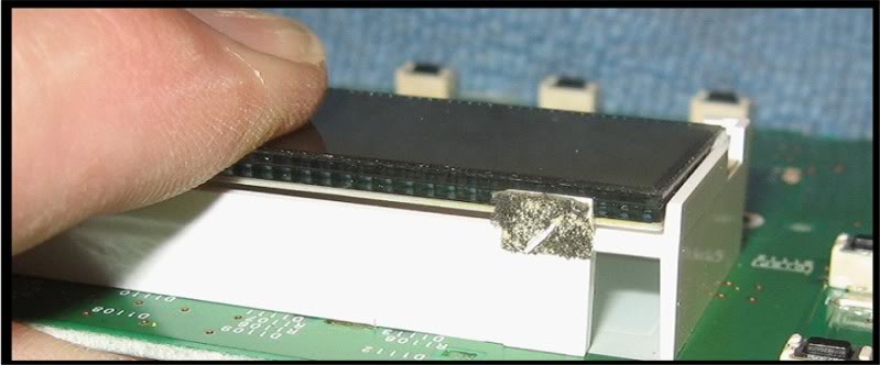
Because the legs will want to return somewhat to their previous bent position, you must keep pressure on the LCD and white housing while going to the next step. Keep the LCD seated in the housing and the housing seated to the board.
Place the metal housing over the plastic housing and insert the legs into the matching slots in the board. Note that the legs are spaced apart differently on each side, you cannot install the metal housing incorrectly. If it is not going in, check the legs relative to the slots and turn the housing around if you need to.
Turn the board over and while keeping pressure on the housing to prevent the contact legs from springing back, use small needle nose pliers to bend the portion of the legs that come through the slots back into the position they were in before the solder was removed. This will hold everything together.
Re-solder the 4 legs securing the metal LCD housing to the board and bend the ground contact piece back into position.
Use isopropyl alcohol and a soft cloth to clean finger prints, dust and lint off the LCD.
Connect the circuit board to the front of your radio, plug the radio into the wiring harness of the car, turn the ignition to ACC and confirm all the LEDs are lighting up and that the LCD is functioning.
Complete any soldering rework that is required.
Use the air duster to blow any lint or dust from the inside of the radio front face and double check the window that covers the LCD for lint, hair, dust, etc.
Disconnect the circuit board from the radio, place it back into position inside the front face plate and secure it with the 8 screws.
Orient the front face into proper position on the front of the radio and snap it back on.
Place the radio back into the center console and secure it with the 4 screws into the mounting bracket.
Connect the radio while re-installing the center console.
Re-install the center console in the reverse order you took it out.
Re-install the lower finisher AND REMEMBER TO CONNECT THE AC CONTROLS RIBBON CABLE.
For a PDF of the entire procedure, PM me.
NOTE - The procedure for convering a Bose stock head unit should be fairly similar. I don't have the pics or experience with the Bose unit. There might be additional LEDs involved.
Use the AC Controls procedure to remove the lower finisher and set it aside.
Use the Center Console Gauges procedure to loosen and remove the center console
Remove the two screws on each side of the radio that secure it to the mounting bracket, pull the radio out and move it to your work area.
Use a small flat tip screw driver to pry the black plastic front face loose at each corner, top and bottom. After the tip is slightly in the hole, as shown below, pry up the tab just a little to unlock the black plastic and then leverage the blade against the metal enclosure by moving the base of the blade forward. The corner will come out just a bit and you will have to prevent it from snapping back into place when you do the other corners.
Once the face has been loosened from the metal enclosure, you should be able to pull it straight off.
Pull the volume **** straight off, should be able to do this with your fingers.
Turn the front plate face down and remove the 8 screws, circled below, that hold the circuit board to the back of the black plastic face and remove the circuit board.
The next step is to remove the LCD housing., circled in the pic below.
Turn the circuit board over so that it is face down.
De-solder the four legs, circled below, that secure the metal housing to the circuit board. One leg has a small metal grounding contact over it that will have to be bent out of the way to access the leg. See the pic below which shows the contact already bent back, its next to the upper right solder joint.
Use small needle nose pliers to bend the bases of the legs straight so that they will go through the holes in the board.
Use a small flat blade screw driver to pry each leg of the metal housing up through its hole in the board. Make sure you get the tip of the blade under the metal piece rather than the white plastic.
After all 4 corners are loose; pull up on the metal housing and remove it.
Orient the board so that the contact legs are on the far side and slowly and carefully push up and rotate the white plastic housing back so that the contact legs bend back as shown below. This will bend the contact legs but as long as these are not bent back and forth too much, they will not fatigue enough to crease or break.
Use your thumbnail or fingernail to separate the white housing from the LCD.
From the side of the white housing closest to the contact legs and the circuit board, wiggle the white housing loose and pull it out from under the LCD. You have to pull the housing down and then back to get the corners free. See the picture with the red arrows below.
Remove the yellow diffuser from the white housing.
Wet sand the diffuser with 600 grit sandpaper to remove the yellow coating from the diffuser.
Place the diffuser back into the white housing. Be sure the tab goes into the proper location so the diffuser lays in flat.
Bend the LCD contact legs so the LCD is completely vertical. This will provide room for de-soldering the LEDs.
Remove and replace the type 0603 LEDs that are circled in red and the type 0805 LEDs that are circled in white. You can use different colors here if you want the LCD display and / or the volume **** to stand out.
Reinstall the white housing with the diffuser in place. Bring the housing in from under and behind so you get the corners around the edge of the LCD. The fins on the contacts side of the housing should slip between the contact legs.
Hold the white housing and the LCD together at both ends and carefully and slowly bring them together back down into position on the board. Note the two pegs in the bottom of the housing that should match up with the holes in the board. The left peg in this picture is obscured but the right side and the matched hole have been marked in red in the picture above.
Make sure the LCD is fully and evenly seated in the top of the housing. Note in the picture below that there is no gap between the LCD and the diffuser and the housing.
Because the legs will want to return somewhat to their previous bent position, you must keep pressure on the LCD and white housing while going to the next step. Keep the LCD seated in the housing and the housing seated to the board.
Place the metal housing over the plastic housing and insert the legs into the matching slots in the board. Note that the legs are spaced apart differently on each side, you cannot install the metal housing incorrectly. If it is not going in, check the legs relative to the slots and turn the housing around if you need to.
Turn the board over and while keeping pressure on the housing to prevent the contact legs from springing back, use small needle nose pliers to bend the portion of the legs that come through the slots back into the position they were in before the solder was removed. This will hold everything together.
Re-solder the 4 legs securing the metal LCD housing to the board and bend the ground contact piece back into position.
Use isopropyl alcohol and a soft cloth to clean finger prints, dust and lint off the LCD.
Connect the circuit board to the front of your radio, plug the radio into the wiring harness of the car, turn the ignition to ACC and confirm all the LEDs are lighting up and that the LCD is functioning.
Complete any soldering rework that is required.
Use the air duster to blow any lint or dust from the inside of the radio front face and double check the window that covers the LCD for lint, hair, dust, etc.
Disconnect the circuit board from the radio, place it back into position inside the front face plate and secure it with the 8 screws.
Orient the front face into proper position on the front of the radio and snap it back on.
Place the radio back into the center console and secure it with the 4 screws into the mounting bracket.
Connect the radio while re-installing the center console.
Re-install the center console in the reverse order you took it out.
Re-install the lower finisher AND REMEMBER TO CONNECT THE AC CONTROLS RIBBON CABLE.
For a PDF of the entire procedure, PM me.
Last edited by lbz; 08-04-2009 at 07:37 PM. Reason: Changed diffuser sanding recommendation.
07-18-2009, 07:26 AM
#55
Section 5 - The Navigation Control Panel
Use a flat blade screwdriver between the mask (1) and the Navi control panel (2) to remove the mask.
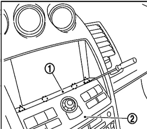
Remove the two screws (A) and pull the Navi control panel out and disconnect the wiring connector in the back.
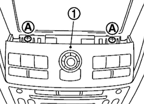
Remove the joystick **** by pulling it straight up and off.
Turn the panel face down and remove the 4 screws in the back holding the housing together.
Remove the front cover and set it aside face down.
NOTE – be careful with the front cover; be sure you don’t let any of the control actuators fall out.
Keeping the control panel face down will prevent the actuators from falling out.
Lift the back cover off and turn it over. DO NOT attempt to remove the connector from the board.
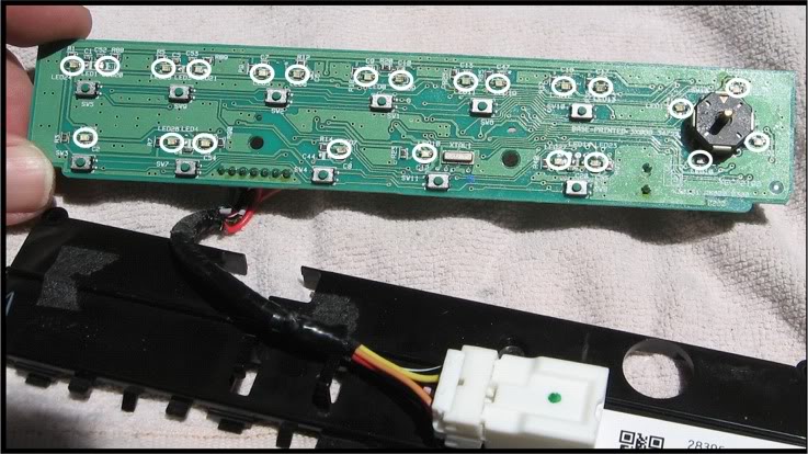
Remove and replace all the LEDs circled in the picture below using 0805 type LEDs. The cathode ends of all the LEDs are facing towards the joystick control.
Lay the circuit board face down into the face plate, orient the back cover into place, install the 4 securing screws and put the joy stick **** back on.
Connect the wiring harness connector and snap the control panel back into place.
Use a flat blade screwdriver between the mask (1) and the Navi control panel (2) to remove the mask.
Remove the two screws (A) and pull the Navi control panel out and disconnect the wiring connector in the back.
Remove the joystick **** by pulling it straight up and off.
Turn the panel face down and remove the 4 screws in the back holding the housing together.
Remove the front cover and set it aside face down.
NOTE – be careful with the front cover; be sure you don’t let any of the control actuators fall out.
Keeping the control panel face down will prevent the actuators from falling out.
Lift the back cover off and turn it over. DO NOT attempt to remove the connector from the board.
Remove and replace all the LEDs circled in the picture below using 0805 type LEDs. The cathode ends of all the LEDs are facing towards the joystick control.
Lay the circuit board face down into the face plate, orient the back cover into place, install the 4 securing screws and put the joy stick **** back on.
Connect the wiring harness connector and snap the control panel back into place.
Last edited by lbz; 07-26-2009 at 02:04 PM.
07-18-2009, 11:15 PM
#56
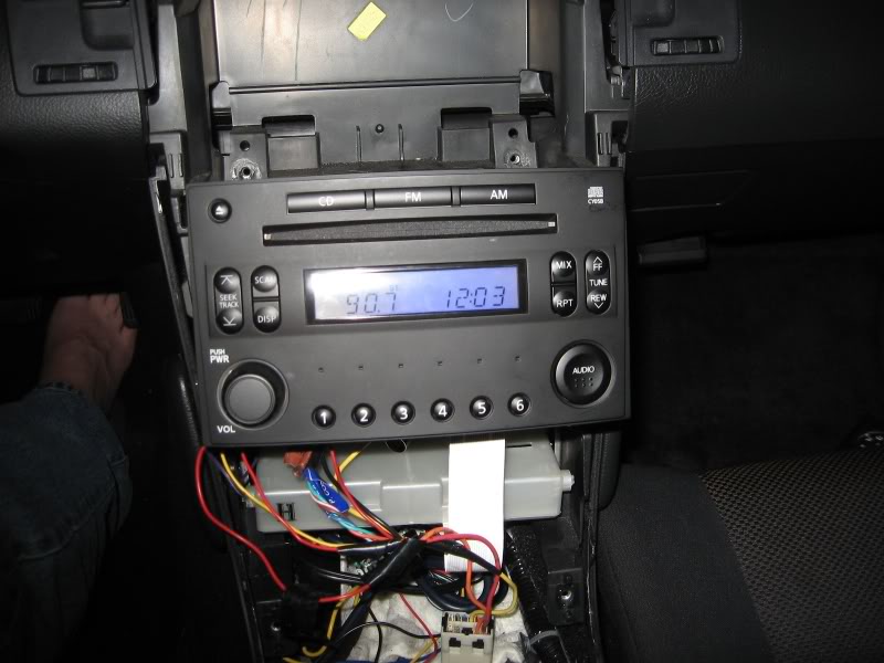
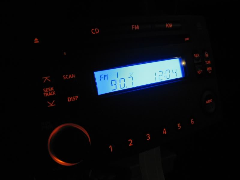
FINALLY got a pic of a partial radio conversion, just the LCD. I don't expect I will do the rest, just wanted to see what I could do with some extra blue 0805's that I had. I normall don't have this installed anyway.
Both night shots one with flash and one without.
I think it would look sick to have the volume **** lit up with RED and all the rest in blue.
Both night shots one with flash and one without.
I think it would look sick to have the volume **** lit up with RED and all the rest in blue.
Last edited by lbz; 07-26-2009 at 02:05 PM.
07-19-2009, 09:32 AM
#57
Section 6 - Steering Wheel Cluster - Part 1
Before starting:
- With the engine cold, put the key in the ACC position and take a picture of all the gauges for future reference when re-setting the needles.
- Comletely fill the gas tank and with the car warmed up take pictures of the gauges for future reference when re-setting the needles.
NOTE – Differences between 6MT and Automatic are noted where applicable.
NOTE - No information about changing the stock amber colored needles is provided. The stock needles are made of amber colored plastic, are not coated, and to my knowledge, cannot be modified to be made clear.
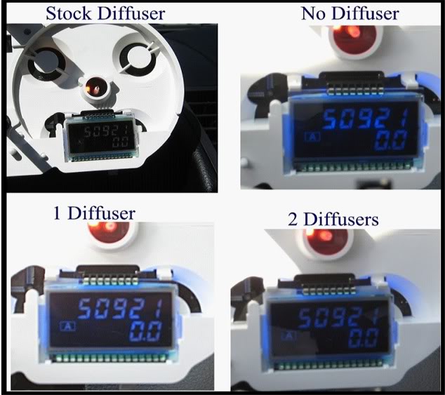
Light Diffusers: These catch and spread light to prevent LED “hot spots” on the LCDs.
Daytime comparison of stock diffuser (left) against 2 layers of Roscolux #103 white (right). Using the stock diffuser, the backlighting is more evenly spread & no LED hotspots.
Night picture with stock diffuser (left) and 2 layers of #103 white (right).
OPTIONS: Procedures for options are located at most appropriate places.
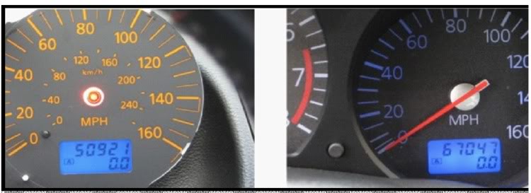
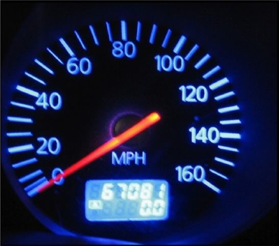
Option 1 - Odometer LCD Reversal: The center console LCD has light characters & dark background while the odometer LCD has the opposite. You can make them match by using polarity reversing film.
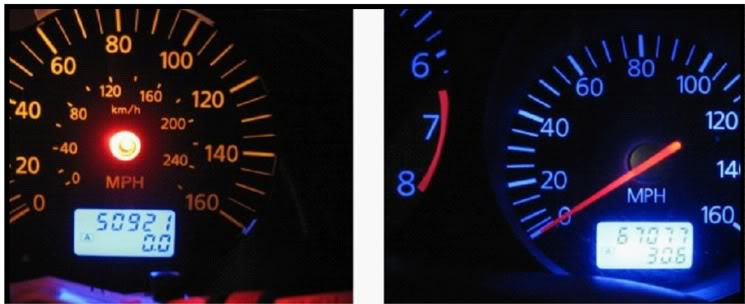
I reversed the odometer, using 1 layer of diffuser, and the result is the odometer became less visible. I like the appearance but this is personal. See comparison pics below.
If you decide to reverse the odometer LCD, using a diffuser gel (Roscolux #103)works better than the stock diffuser.
Day pics
Night pic of reversed, 1 layer of #103 white diffuser
Option 2 – Blinker Indicator Conversion
Make the blinker indicators in the steering cluster match your conversion. If doing green, skip this.
Over the indicators are overlays of a green arrow surround by black. Removing the green coating over the arrows while keeping edges clean is the challenge. These cant be ordered from Nissan so be careful. When I come up with something, I will post it.
Procedure
Pull down on the right side front and rear edges of the driver’s side lower dash panel, then on the left . Pull down enough to access under the steering wheel. No need to remove or disconnect cables, just let it hang.
Use a flat blade screw driver to pry out the ignition trim ring (arrow below)

Remove the four screws in the lower steering wheel cover. One is in the release lever channel so put the release lever down first. Pull the cover off.

Remove the four 10mm bolts from the mounting bracket. You may have to thread the extension behind a wire bundle on the left side.

NOTE – It is normal for the upper steering wheel cover to come out with the gauge cluster
Gently lift the gauge cluster up, tilt it back and disconnect the wiring connector. Note – you may have to unsnap the upper steering wheel cover from the top of the steering wheel for it to come loose.

Set the cluster face down on a soft towel, remove the 6 screws that hold the upper steering wheel cover to the bracket and remove the cover.

Pry each section of the rear cover loose and remove it.

Unplug the two wiring connectors and pull the bundles from their guides. Remove the two screws from the back of the cluster.

The back cover wraps around from the back towards the front under the lower half of the ends. Pop one end of the back cover off of one of the lower corners. Then do the other corner.

Carefully work the back cover off of the cluster.

Snap the top cover loose at either end under the lower silver button. The silver buttons are fastened and will move with the cover. The silver (painted black in this picture) metal bezel may stay attached to the top cover or it may not. Either way is OK. The clear plastic lens will stay attached to the cluster.

Turn it face down, remove the 4 screws from the mounting bracket and pull it off.

Remove the insulator.

Pry loose the clips on the top and bottom that hold the black trim piece to the board housing.
TOP

BOTTOM

Pull the circuit board housing free and set it face up. Set the front trim and plastic face piece face up to minimize dust collecting inside.

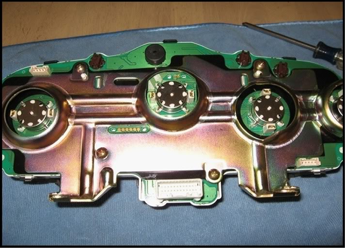
Remove the gauge needles as described for the center console gauges. NOTE- be careful of other gauge needles and needle stops when arranging your prying tools, check for best placement before you start prying. NOTE – make sure your work area is well lit and in an open area. The needles can shoot up when released so being able to see where they land is important.

Peel up the old gauge face. If you hit sticky areas with excess glue, use a hair dryer to soften the glue. Keep the stock gauge faces handy, you will need the needle stops.
Carefully pry the odometer LCD from its socket. First, pry the retaining clips back enough so they clear the edge of the LCD. If you happen to break one or both of these, don’t worry about it. The LCD will stay in its socket without them.
Place the blade under the white plastic diffuser between the bottom of the LCD and the housing. This will protect the LCD from the tool. Start with one corner, pry a little, go to another corner and so on so you don’t bend the legs of the LCD. When it is loose, grip by the end edges and lift straight out. KEEP the white plastic diffuser. For cars with automatic transmissions, repeat this step for the gear selection indicator LCD.


Place the housing face down. Pry the board loose from the housing along the edges.

Press in the center tabs to release and remove the circuit board from the housing.

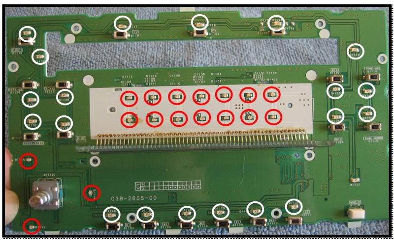
Turn the circuit board face up and replace the LED’s and resistors that are circled in the picture below.
NOTE – The LEDs that are not circled are warning indicators. It is suggested you leave these alone so they stand out for your attention. They are normally not lit and will not detract from your conversion. The quantities listed in the tools and supplies list do not include replacing warning LEDs.
NOTE - The LEDs circled in white will be present for cars equipped with automatic transmissions.
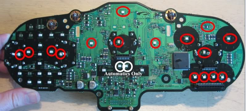
NOTE – The horizontal LEDs must use the LOWER pair of contacts on the board instead of the upper that are used for the center console. See the pics below. The vertical LEDs next to the needle stems are oriented 90 degrees counter clockwise from the rest of the LEDs. Use the two pads CLOSEST to the needle stem on the right hand and the center needle stems. Use the outer pads on the left needle stem. The left one is different because the pads are on the other side of the stem. All the LED cathode notches are facing to the right when the board is oriented as shown. The vertically oriented LEDs have the cathode notch facing the top edge.

Take the board to the car, plug it into the wiring connector, turn the key to the ACC position and check your work.
NOTE – The center console gauge board must be plugged in for the this board to function.
For a PDF of the procedure, PM me.
Before starting:
- With the engine cold, put the key in the ACC position and take a picture of all the gauges for future reference when re-setting the needles.
- Comletely fill the gas tank and with the car warmed up take pictures of the gauges for future reference when re-setting the needles.
NOTE – Differences between 6MT and Automatic are noted where applicable.
NOTE - No information about changing the stock amber colored needles is provided. The stock needles are made of amber colored plastic, are not coated, and to my knowledge, cannot be modified to be made clear.
Light Diffusers: These catch and spread light to prevent LED “hot spots” on the LCDs.
Daytime comparison of stock diffuser (left) against 2 layers of Roscolux #103 white (right). Using the stock diffuser, the backlighting is more evenly spread & no LED hotspots.
Night picture with stock diffuser (left) and 2 layers of #103 white (right).
OPTIONS: Procedures for options are located at most appropriate places.
Option 1 - Odometer LCD Reversal: The center console LCD has light characters & dark background while the odometer LCD has the opposite. You can make them match by using polarity reversing film.
I reversed the odometer, using 1 layer of diffuser, and the result is the odometer became less visible. I like the appearance but this is personal. See comparison pics below.
If you decide to reverse the odometer LCD, using a diffuser gel (Roscolux #103)works better than the stock diffuser.
Day pics
Night pic of reversed, 1 layer of #103 white diffuser
Option 2 – Blinker Indicator Conversion
Make the blinker indicators in the steering cluster match your conversion. If doing green, skip this.
Over the indicators are overlays of a green arrow surround by black. Removing the green coating over the arrows while keeping edges clean is the challenge. These cant be ordered from Nissan so be careful. When I come up with something, I will post it.
Procedure
Pull down on the right side front and rear edges of the driver’s side lower dash panel, then on the left . Pull down enough to access under the steering wheel. No need to remove or disconnect cables, just let it hang.
Use a flat blade screw driver to pry out the ignition trim ring (arrow below)
Remove the four screws in the lower steering wheel cover. One is in the release lever channel so put the release lever down first. Pull the cover off.
Remove the four 10mm bolts from the mounting bracket. You may have to thread the extension behind a wire bundle on the left side.
NOTE – It is normal for the upper steering wheel cover to come out with the gauge cluster
Gently lift the gauge cluster up, tilt it back and disconnect the wiring connector. Note – you may have to unsnap the upper steering wheel cover from the top of the steering wheel for it to come loose.
Set the cluster face down on a soft towel, remove the 6 screws that hold the upper steering wheel cover to the bracket and remove the cover.
Pry each section of the rear cover loose and remove it.
Unplug the two wiring connectors and pull the bundles from their guides. Remove the two screws from the back of the cluster.
The back cover wraps around from the back towards the front under the lower half of the ends. Pop one end of the back cover off of one of the lower corners. Then do the other corner.
Carefully work the back cover off of the cluster.
Snap the top cover loose at either end under the lower silver button. The silver buttons are fastened and will move with the cover. The silver (painted black in this picture) metal bezel may stay attached to the top cover or it may not. Either way is OK. The clear plastic lens will stay attached to the cluster.
Turn it face down, remove the 4 screws from the mounting bracket and pull it off.
Remove the insulator.
Pry loose the clips on the top and bottom that hold the black trim piece to the board housing.
TOP
BOTTOM
Pull the circuit board housing free and set it face up. Set the front trim and plastic face piece face up to minimize dust collecting inside.
Remove the gauge needles as described for the center console gauges. NOTE- be careful of other gauge needles and needle stops when arranging your prying tools, check for best placement before you start prying. NOTE – make sure your work area is well lit and in an open area. The needles can shoot up when released so being able to see where they land is important.
Peel up the old gauge face. If you hit sticky areas with excess glue, use a hair dryer to soften the glue. Keep the stock gauge faces handy, you will need the needle stops.
Carefully pry the odometer LCD from its socket. First, pry the retaining clips back enough so they clear the edge of the LCD. If you happen to break one or both of these, don’t worry about it. The LCD will stay in its socket without them.
Place the blade under the white plastic diffuser between the bottom of the LCD and the housing. This will protect the LCD from the tool. Start with one corner, pry a little, go to another corner and so on so you don’t bend the legs of the LCD. When it is loose, grip by the end edges and lift straight out. KEEP the white plastic diffuser. For cars with automatic transmissions, repeat this step for the gear selection indicator LCD.
Place the housing face down. Pry the board loose from the housing along the edges.
Press in the center tabs to release and remove the circuit board from the housing.
Turn the circuit board face up and replace the LED’s and resistors that are circled in the picture below.
NOTE – The LEDs that are not circled are warning indicators. It is suggested you leave these alone so they stand out for your attention. They are normally not lit and will not detract from your conversion. The quantities listed in the tools and supplies list do not include replacing warning LEDs.
NOTE - The LEDs circled in white will be present for cars equipped with automatic transmissions.
NOTE – The horizontal LEDs must use the LOWER pair of contacts on the board instead of the upper that are used for the center console. See the pics below. The vertical LEDs next to the needle stems are oriented 90 degrees counter clockwise from the rest of the LEDs. Use the two pads CLOSEST to the needle stem on the right hand and the center needle stems. Use the outer pads on the left needle stem. The left one is different because the pads are on the other side of the stem. All the LED cathode notches are facing to the right when the board is oriented as shown. The vertically oriented LEDs have the cathode notch facing the top edge.
Take the board to the car, plug it into the wiring connector, turn the key to the ACC position and check your work.
NOTE – The center console gauge board must be plugged in for the this board to function.
For a PDF of the procedure, PM me.
Last edited by lbz; 11-26-2009 at 09:42 AM.
07-19-2009, 09:51 AM
#58
Steering Wheel Cluster Part 2
NOTE – Complete these steps one board at a time. This will provide you with a reference board for LED lens location and reassembly.
Remove the single screw securing the circuit board to the inside of the housing.
Remove the circuit board and the rubber housing. The small bead of black plastic circled below will tear off. The screw holds the board in place well enough for the switches to work the same as before.

Pull the board from the rubber housing.

Make a note or take a picture of the position of the LED lenses relative to the edge of the circuit board. When you solder the new ones in they should be in generally the same position.
Remove the stock LEDs.
NOTE - The shorter leg of each new LED is the cathode leg.
NOTE –Notice in the picture below the position of the cathode symbols which are circled. On the right hand LED, the symbol is next to the right hand contact. On the lower, left hand LED, the symbol is next to the left contact.
For some reason, soldering in the left hand, lower LED, using the factory markings does not work. When soldering the left hand, lower LED, put the shorter leg in the right hand hole, the same way as the right hand, upper LED.

Place the circuit board and the rubber housing back into position and re-attach with the screw.
Repeat the process on the other board.
Go back to the main board and place it face down into the white housing, press softly and evenly around the edges and then in the center until the two clips in the center area clip onto the back of the board.
Turn the housing face up.
If you do not want to change your odometer LCD to match the center console LCD - Skip the next "Option #1" section and proceed to "End of Option #1 Section"
OPTION #1- odometer LCD reversal. If you are not reversing your odometer LCD, go to the next section that starts with “Place the factory diffuser back into position.”
First peel up the anti-glare piece from the odometer LCD; try not to damage this piece as you will need to use it later. Notice that the razor blade is covering up the black border around the LCD but is under the anti-glare piece.

Use the razor blade again to remove the polarizing strip. Notice the black border goes away as the razor blade goes under the edge. Scrape this layer off entirely with the razor blade.
Use Isopropyl alcohol or adhesive remover and the razor blade to remove ALL the old adhesive. The glass should be perfectly clean before proceeding. Inspect the glass at an angle to a light source to reveal the smallest spots of glue.

The LCD should look like the one shown below, no black border.

Both sides of the reversal strip have a protective film. One has an “A” written on it. This is the adhesive side.
Peel the protective layer off of the adhesive side, line it up with the LCD length wise and place only one end down onto the glass. Make sure it is lined up along the edge.
Keep the strip arched back so that only a small portion of it touches the glass. Use a finger or your thumb from you other hand to press down on the piece of strip that is touching the glass.
Slowly lower / unbend the strip and keep pressing and moving up the glass with your finger to push air bubbles out.
Once completely on the glass, use the edge of a credit card or driver’s license as a squeegee to push out any remaining air bubbles.
DO NOT REMOVE THE PROTECTIVE LAYER YET. Keep it on until just before you re-affix the anti-glare strip.
Use the stock diffuser and an Xacto knife as a pattern to cut two layers of Roscolux #103 White diffuser and lay those in where the stock diffuser normally went.
FOR POLARITY REVERSALS - SKIP THE NEXT STEP – you will not be using the stock diffuser
End of Option #1 Section
Place the factory diffuser back into position.

Re-insert the LCD. Do one side first with the LCD tilted that way, then lower the opposite side into place while applying very slight pressure on the legs already inserted. Check to make sure all legs are properly aligned with their respective sockets. If you bend a leg or two, straighten using small needle nose pliers or your thumbnail. The key is to avoid fatiguing the leg by bending it alot.
Slowly and evenly press the LCD into place at BOTH ends and then in the center.
The next four steps are only for those who have installed an odometer polarity reversal strip.
* Remove the thin protective film from the reversal strip
* Apply 1 or 2 very small spots of super glue to each end of the anti-glare strip on the same side that was glued down before you removed it.
* Affix the anti-glare strip on top of the polarity strip.
* If you have an automatic, repeat the polarity reversal strip process for the gear selected indicator LCD.
For a PDF of the entire procedure, PM me.
NOTE – Complete these steps one board at a time. This will provide you with a reference board for LED lens location and reassembly.
Remove the single screw securing the circuit board to the inside of the housing.
Remove the circuit board and the rubber housing. The small bead of black plastic circled below will tear off. The screw holds the board in place well enough for the switches to work the same as before.
Pull the board from the rubber housing.
Make a note or take a picture of the position of the LED lenses relative to the edge of the circuit board. When you solder the new ones in they should be in generally the same position.
Remove the stock LEDs.
NOTE - The shorter leg of each new LED is the cathode leg.
NOTE –Notice in the picture below the position of the cathode symbols which are circled. On the right hand LED, the symbol is next to the right hand contact. On the lower, left hand LED, the symbol is next to the left contact.
For some reason, soldering in the left hand, lower LED, using the factory markings does not work. When soldering the left hand, lower LED, put the shorter leg in the right hand hole, the same way as the right hand, upper LED.
Place the circuit board and the rubber housing back into position and re-attach with the screw.
Repeat the process on the other board.
Go back to the main board and place it face down into the white housing, press softly and evenly around the edges and then in the center until the two clips in the center area clip onto the back of the board.
Turn the housing face up.
If you do not want to change your odometer LCD to match the center console LCD - Skip the next "Option #1" section and proceed to "End of Option #1 Section"
OPTION #1- odometer LCD reversal. If you are not reversing your odometer LCD, go to the next section that starts with “Place the factory diffuser back into position.”
First peel up the anti-glare piece from the odometer LCD; try not to damage this piece as you will need to use it later. Notice that the razor blade is covering up the black border around the LCD but is under the anti-glare piece.
Use the razor blade again to remove the polarizing strip. Notice the black border goes away as the razor blade goes under the edge. Scrape this layer off entirely with the razor blade.
Use Isopropyl alcohol or adhesive remover and the razor blade to remove ALL the old adhesive. The glass should be perfectly clean before proceeding. Inspect the glass at an angle to a light source to reveal the smallest spots of glue.
The LCD should look like the one shown below, no black border.
Both sides of the reversal strip have a protective film. One has an “A” written on it. This is the adhesive side.
Peel the protective layer off of the adhesive side, line it up with the LCD length wise and place only one end down onto the glass. Make sure it is lined up along the edge.
Keep the strip arched back so that only a small portion of it touches the glass. Use a finger or your thumb from you other hand to press down on the piece of strip that is touching the glass.
Slowly lower / unbend the strip and keep pressing and moving up the glass with your finger to push air bubbles out.
Once completely on the glass, use the edge of a credit card or driver’s license as a squeegee to push out any remaining air bubbles.
DO NOT REMOVE THE PROTECTIVE LAYER YET. Keep it on until just before you re-affix the anti-glare strip.
Use the stock diffuser and an Xacto knife as a pattern to cut two layers of Roscolux #103 White diffuser and lay those in where the stock diffuser normally went.
FOR POLARITY REVERSALS - SKIP THE NEXT STEP – you will not be using the stock diffuser
End of Option #1 Section
Place the factory diffuser back into position.
Re-insert the LCD. Do one side first with the LCD tilted that way, then lower the opposite side into place while applying very slight pressure on the legs already inserted. Check to make sure all legs are properly aligned with their respective sockets. If you bend a leg or two, straighten using small needle nose pliers or your thumbnail. The key is to avoid fatiguing the leg by bending it alot.
Slowly and evenly press the LCD into place at BOTH ends and then in the center.
The next four steps are only for those who have installed an odometer polarity reversal strip.
* Remove the thin protective film from the reversal strip
* Apply 1 or 2 very small spots of super glue to each end of the anti-glare strip on the same side that was glued down before you removed it.
* Affix the anti-glare strip on top of the polarity strip.
* If you have an automatic, repeat the polarity reversal strip process for the gear selected indicator LCD.
For a PDF of the entire procedure, PM me.
Last edited by lbz; 07-19-2009 at 12:29 PM.
07-19-2009, 10:02 AM
#59
Steering Wheel Cluster - Part 3
Go to your old stock gauge faces.
Remove the needle stops from the stock gauge faces by pinching the base, on the back side of the gauge face, with tweezers or small needle nose pliers and pushing through the hole from the back out through the front.

Snap the needle stops into the new gauge faces by holding the stem between your thumb and index finger at the base while pushing through the hole from the front to the back. The needle stops should snap in fairly easily.

Apply glue stick to the flat areas of the housing that the gauge face will contact. Be careful around the LCDs. The glue stick can get a bit stringy / messy.
Lay your new gauge face onto the housing and press it into place while rubbing to press out any air bubbles and maximize contact with the glue.
Take the white housing with the new gauge faces installed out to the car. Take the needles with you but DO NOT PUT THE NEEDLES ON YET.
Connect the wiring to the connector in the back and set the housing down in the area where the gauge pod normally rests.
Turn the ignition to the ACC position.
Gently place the fuel gauge needle in the position shown in your reference picture, check it against your picture with your hand away and if correct . If it needs correction, pull it off and start again. Once correct press lightly on the center of the base to snap it onto the stem
Start the car.
Lightly place the RPM and MPH gauge needles onto the positions shown in your reference picture but do NOT snap them into place yet.
For the tach needle, set your RPM shift warning light to trip at 2000 RPM. Rev the engine until the RPM warning light goes solid. It will start blinking at 1500 RPM and go solid at 2000.
When the indicator goes solid, check the position of the needle, if it is correct, let off the gas so the engine returns to normal idle. If needing correction, repeat by remove the RPM needle and place it in the correct position as you hold the RPM at 2000. Once correct, press lightly on the center of the needle base and it will snap onto the stem.
This next step is best performed with a partner. Take the assembly to your car, connect the wiring and tilt it so it’s leaning back. Find an empty street or parking lot without pedestrians or traffic so you can focus on the needles while the car is moving. A partner can steer the car by gripping the bottom of the steering wheel while you keep the speed constant using the center console LCD and set the gauge needle in place.
Use the trip computer to bring the car to 20 MPH. Adjust the MPH gauge needle as needed to match the speed shown in the trip computer LCD. You may not get it on the first try, be patient and get it as close as possible. 10 MPH is too fine to set, if you use 10 MPH, the accuracy will not hold at higher speeds.
When you are confident that you are matching 20 MPH on the speedometer with the LCD, take the car slowly up to 30 and 40 MPH while comparing the LCD with the MPH gauge needle. They should match.
When the LCD and MPH gauge needle match, stop the car and press lightly on the needle base so it clicks into place.
Turn off the car, disconnect the gauge housing from the wiring and return to your work area.
If you do not want to change the color of your blinker indicators, skip the next "Option #2" section and proceed to "End of Option #2".
OPTION #2 – Changing blinker indicator colors: You can change the color of the blinker indicator lights by obtaining replacement LED bulbs from the source specified in the parts list. However, the lenses that sit over the bulbs have a green colored arrow surrounded by black. If you want your colored bulbs (any color other than green) to shine through, you will have to scrape away the green coating. If you are not able to do this very cleanly, you will have blinker indicators with rough edges so give this some thought before proceeding with this section. NOTE - A method of creating replacement clear arrow symbols on the overlay lenses is not provided in this procedure. Think carefully about what you want to do and how you would do it after taking a look at how the blinker indicator overlay lenses are constructed. To my knowledge these lenses are not something you could order from Nissan. You would have to find a used speedometer cluster in order to get replacement lenses. I am working on a process but am not ready to post about it yet.
From the back of the circuit board, twist and pull out the blinker indicator bulb sockets denoted by the arrows in the picture below. The right most bulb is for the High Beams indicator and should not be changed.

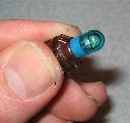
Remove the bulbs from the sockets by wiggling them while pulling. One option is to cover the bulb in tissue and very lightly grip with needle nose pliers but be very careful; breaking the bulb off inside the socket would require replacing the socket. Be patient, keep at it and they will come out.
Insert the new bulbs into the sockets and then put the sockets through the back of the board and twist to lock in.
Use the small flat blade screwdriver to press in on and release the fasteners that hold the clear cover to the front trim piece.
Remove the silver (painted black in this picture) trim piece from the larger one.

Peel the blinker lens pieces off the front black trim piece. Modify the lens piece however you want.
Once you have your blinker lens modification done to your liking, use the glue stick or superglue to re-attach the lens pieces.
Replace the silver (painted black in this picture) trim piece.
Before you snap the clear cover back onto the black trim, use the air duster to remove hairs, threads, dust, etc from the inside of the lens.
Thoroughly inspect the inside surface of the lens before snapping it back into place.
You don’t want to be staring at a thread or hair trapped inside your main gauge cluster.

End of Option #2 Section
Place the trim piece over and onto the white housing

Press all the snaps into place on the top and bottom edges
Turn the assembly over and replace the insulator

Put the mounting bracket back on and install the four securing screws.
Work the top cover into place making sure the wires are all in the channel. If the silver metal bezel is separated from the top cover, place the metal bezel in position first. Then work the top cover into place and snap the two together along the top edge where they meet.

Work the lower cover into place. This can be a bit of a challenge. The slack in the wire must not get pinched by or between the covers. The wire bundles should go under the small metal clips inside the ends of the lower cover and from there up through the channel. Some slack in the bundle will help it go under the clip.

Once the bundle is in place, snap the two ends together.
Cable in the channel and covers snapped together on the right end.

Cable in the channel and covers snapped together on the left end.

Route the bundle on the left end and plug the connector in.

Route the bundle on the right end and plug the connector in.
Fasten the two screws that go into the back cover.
Place the upper steering wheel cover in position with the finished side of the cover facing down and secure it to the bracket with the six screws.
Take the cluster back to the car, place it in position, tilt it back, connect the wiring and work the legs into position.
Replace the four securing bolts
Replace the lower steering wheel cover, be sure to thread the adjustment lever through the opening in the lower cover, and reinstall the four securing screws. Replace the screw in the adjustment lever channel first.
Snap the lower dash cover corners back into place.
For a PDF of the procedure, PM me.
Go to your old stock gauge faces.
Remove the needle stops from the stock gauge faces by pinching the base, on the back side of the gauge face, with tweezers or small needle nose pliers and pushing through the hole from the back out through the front.
Snap the needle stops into the new gauge faces by holding the stem between your thumb and index finger at the base while pushing through the hole from the front to the back. The needle stops should snap in fairly easily.
Apply glue stick to the flat areas of the housing that the gauge face will contact. Be careful around the LCDs. The glue stick can get a bit stringy / messy.
Lay your new gauge face onto the housing and press it into place while rubbing to press out any air bubbles and maximize contact with the glue.
Take the white housing with the new gauge faces installed out to the car. Take the needles with you but DO NOT PUT THE NEEDLES ON YET.
Connect the wiring to the connector in the back and set the housing down in the area where the gauge pod normally rests.
Turn the ignition to the ACC position.
Gently place the fuel gauge needle in the position shown in your reference picture, check it against your picture with your hand away and if correct . If it needs correction, pull it off and start again. Once correct press lightly on the center of the base to snap it onto the stem
Start the car.
Lightly place the RPM and MPH gauge needles onto the positions shown in your reference picture but do NOT snap them into place yet.
For the tach needle, set your RPM shift warning light to trip at 2000 RPM. Rev the engine until the RPM warning light goes solid. It will start blinking at 1500 RPM and go solid at 2000.
When the indicator goes solid, check the position of the needle, if it is correct, let off the gas so the engine returns to normal idle. If needing correction, repeat by remove the RPM needle and place it in the correct position as you hold the RPM at 2000. Once correct, press lightly on the center of the needle base and it will snap onto the stem.
This next step is best performed with a partner. Take the assembly to your car, connect the wiring and tilt it so it’s leaning back. Find an empty street or parking lot without pedestrians or traffic so you can focus on the needles while the car is moving. A partner can steer the car by gripping the bottom of the steering wheel while you keep the speed constant using the center console LCD and set the gauge needle in place.
Use the trip computer to bring the car to 20 MPH. Adjust the MPH gauge needle as needed to match the speed shown in the trip computer LCD. You may not get it on the first try, be patient and get it as close as possible. 10 MPH is too fine to set, if you use 10 MPH, the accuracy will not hold at higher speeds.
When you are confident that you are matching 20 MPH on the speedometer with the LCD, take the car slowly up to 30 and 40 MPH while comparing the LCD with the MPH gauge needle. They should match.
When the LCD and MPH gauge needle match, stop the car and press lightly on the needle base so it clicks into place.
Turn off the car, disconnect the gauge housing from the wiring and return to your work area.
If you do not want to change the color of your blinker indicators, skip the next "Option #2" section and proceed to "End of Option #2".
OPTION #2 – Changing blinker indicator colors: You can change the color of the blinker indicator lights by obtaining replacement LED bulbs from the source specified in the parts list. However, the lenses that sit over the bulbs have a green colored arrow surrounded by black. If you want your colored bulbs (any color other than green) to shine through, you will have to scrape away the green coating. If you are not able to do this very cleanly, you will have blinker indicators with rough edges so give this some thought before proceeding with this section. NOTE - A method of creating replacement clear arrow symbols on the overlay lenses is not provided in this procedure. Think carefully about what you want to do and how you would do it after taking a look at how the blinker indicator overlay lenses are constructed. To my knowledge these lenses are not something you could order from Nissan. You would have to find a used speedometer cluster in order to get replacement lenses. I am working on a process but am not ready to post about it yet.
From the back of the circuit board, twist and pull out the blinker indicator bulb sockets denoted by the arrows in the picture below. The right most bulb is for the High Beams indicator and should not be changed.
Remove the bulbs from the sockets by wiggling them while pulling. One option is to cover the bulb in tissue and very lightly grip with needle nose pliers but be very careful; breaking the bulb off inside the socket would require replacing the socket. Be patient, keep at it and they will come out.
Insert the new bulbs into the sockets and then put the sockets through the back of the board and twist to lock in.
Use the small flat blade screwdriver to press in on and release the fasteners that hold the clear cover to the front trim piece.
Remove the silver (painted black in this picture) trim piece from the larger one.
Peel the blinker lens pieces off the front black trim piece. Modify the lens piece however you want.
Once you have your blinker lens modification done to your liking, use the glue stick or superglue to re-attach the lens pieces.
Replace the silver (painted black in this picture) trim piece.
Before you snap the clear cover back onto the black trim, use the air duster to remove hairs, threads, dust, etc from the inside of the lens.
Thoroughly inspect the inside surface of the lens before snapping it back into place.
You don’t want to be staring at a thread or hair trapped inside your main gauge cluster.
End of Option #2 Section
Place the trim piece over and onto the white housing
Press all the snaps into place on the top and bottom edges
Turn the assembly over and replace the insulator
Put the mounting bracket back on and install the four securing screws.
Work the top cover into place making sure the wires are all in the channel. If the silver metal bezel is separated from the top cover, place the metal bezel in position first. Then work the top cover into place and snap the two together along the top edge where they meet.
Work the lower cover into place. This can be a bit of a challenge. The slack in the wire must not get pinched by or between the covers. The wire bundles should go under the small metal clips inside the ends of the lower cover and from there up through the channel. Some slack in the bundle will help it go under the clip.
Once the bundle is in place, snap the two ends together.
Cable in the channel and covers snapped together on the right end.
Cable in the channel and covers snapped together on the left end.
Route the bundle on the left end and plug the connector in.
Route the bundle on the right end and plug the connector in.
Fasten the two screws that go into the back cover.
Place the upper steering wheel cover in position with the finished side of the cover facing down and secure it to the bracket with the six screws.
Take the cluster back to the car, place it in position, tilt it back, connect the wiring and work the legs into position.
Replace the four securing bolts
Replace the lower steering wheel cover, be sure to thread the adjustment lever through the opening in the lower cover, and reinstall the four securing screws. Replace the screw in the adjustment lever channel first.
Snap the lower dash cover corners back into place.
For a PDF of the procedure, PM me.
Last edited by lbz; 07-19-2009 at 12:28 PM.

