
Interior LED Conversion


Overview
This thread provides information for converting the interior LED lighting for model years 2003 - 2008. The procedure is broken down into sections that are located in separate postings. Larger sections are broken down into parts due to posting size limitations.
NOTE: The sections listed below can be done in any particular order. They may appear a bit disjointed in this list because the information was posted after the work was done. The sequence is different in the PDF and has more of a logical flow to it.
Section 1 - Door handles
Section 2A - AC Controls for 03 - 05
Section 3 - Center Console Gauge Cluster
Section 2B - AC Controls for 06 - 08
Section 4 - Stock Radio - non Bose (procedure should be fairly similar, I just don't have pics to document the Bose unit)
Section 5 - Navigation
Section 6 - Steering Wheel Gauge Cluster (speedo / tach)
Section 7 - Seat Control Rocker Switches
Section 8 - 06 - 08 cup holders
Section 9 - Steering Wheel Controls - NOT PUBLISHED YET - but you will need 7 of the PLCC-2 type LEDs
Some of the postings from others may appear disjointed. This is because the entire thread has been cleaned up and consolidated. Information that others have posted that added creative, technial or procedeural information is retained. If a comment you posted is missing, no offense, the project took a while to complete and document fully and the intent is to consolidate and clean up the info.
For a complete PDF version of this procedure, please send me a PM.
Per the nature of the forum, some of this information was gathered and posted by others and I put my own experience and words to it or I provide a link. A good portion of it is from my own research and experience converting my own car.
My postings are not meant to be the final or complete and total word on the subject and I don't mean to take credit for anything that isn't mine. My intent is to provide a single place for information that was spread out in various threads.
A note about the E-Bay kits. I started with the E-Bay kit and soon determined that the result would be half the interior converted and the other half still stock amber. The E-bay kits only cover the center console 3 gauge cluster and the steering wheel cluster. Also, they do not address how to solder 2 contact LEDs onto the 4 contact locations on the boards.
The parts information in this procedure covers blue, green, red and white LEDs and is subject to change without notice and without any updates to this procedure.
If you decide to get LEDs off e-bay, my experience is that many sellers are located in China / Hong Kong and while they may say "Free Shipping", they mean free to them. They typically have very agressive pricing and I have not been burned but sometimes they ship via US Postal Service cash on delivery without telling you. This can result in a delay while the local post office notifies you that you need to pick up and pay for shipping.
Solder training is not included in this thread, unless someone else adds something. If you cannot solder, it's not recommended that you get into this without lining up a resource. You can check local electronics repair shops, they should be able to do the work for you.
Using the stock gauge faces will not give you the results you see in the pics posted in this thread. The stock gauge faces have an orange backing that cannot be removed. New gauge faces can be purchased from Blackcatcustom.com at http://www.blackcatcustom.com/Nissan%20350Z.htm
Delivery time is typically in the range of 2 weeks.
Differences between automatic and manual transmission as well as the changes in the AC controls between 03-05 and 06-08 are included. Some minor differences in disassembly of door handle controls exist but are not documented here.
A note about brightness. LED lighting in daytime is almost completely washed out with the exception of LCDs (center console trip computer, odometer and gear selection indicator on automatics) and push button LEDs on the AC controls. Some posts in other threads talk about changing out resistors to get better brightness. Forum member Acree (who to my knowledge was one of the first to post LED information) posted that due to a voltage regulator, changing the resistors had no effect. I never got into changing resistors and no information about it is included in this thread. I've experimented with LEDs with higher MCD ratings and these had no effect as well.
A note about diffusing gels. I experimented with diffusing gels and determined that the stock diffusers, after removing the yellow coating (where present), provided the best results but as with all things, different opinions and experiences exist and some information regarding the use of gels is included in this thread and is present elsewhere in the forum.
Tools, Supplies and Costs
Tools
Supplies
Costs:
LED’s roughly cost $1.00 each after you include shipping. LED turn signal indicator bulb replacements cost $5.00 each. Depending on the number of LEDs you need, the cost can range roughly between $75 and $125. Gauge faces start at $109.00 and go up from there depending on any customizations you want.
If you are doing this yourself, you can budget $225 - $250 for the costs of all LEDs, gauge faces and shipping and you should be close. If you are not doing this yourself, labor charges can vary widely from professional electronics repair shops to a friend who knows how to solder so labor estimates are not provided here.
Ordering LEDs:
I reference DigiKey http://www.digikey.com as a source for LEDs only because I was able to find part numbers fairly quickly and easily on their site. I am not necessarily endorsing DigiKey nor am I affiliated with them in any way. Another source you could use is Mouser.com http://www.mouser.com though their part numbers are not provided.
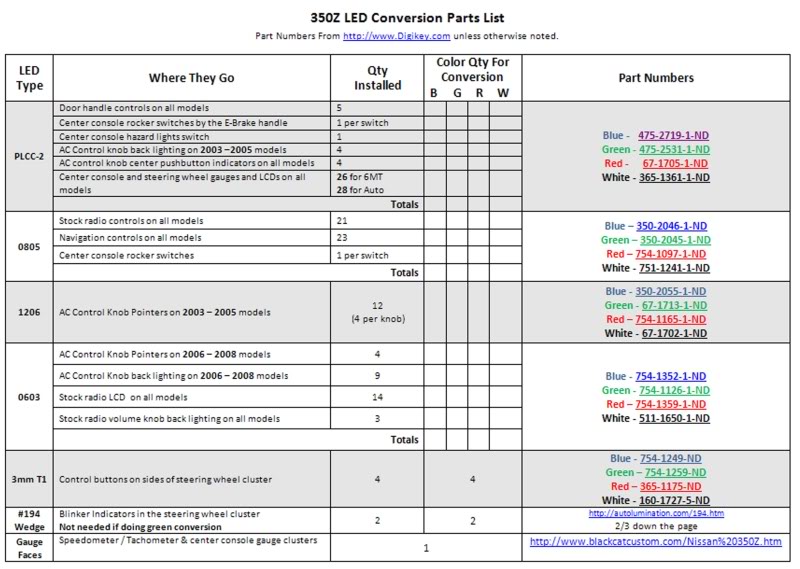
Use the tables below to determine which parts and quantities to order. There are six different types of LEDs used. The LEDs used for the AC controls changed after the 2005 model year. Some people like to mix and match colors. If you look at the table carefully, you will see which LEDs are used, how many and where they are used.
Use the “Color QTY For Conversion” column to enter the number of LEDs you will need to order for each color you want to use. B= Blue, G=Green, R=Red and W=White.
Once you know your quantities, use the part numbers to order on line. Keep adding parts and quantities to your order until you are ready to check out. You do not need to setup an account in order to order. Note – if a particular LED is not available from DigiKey, check E-Bay for the type and color you want. If you right click on the image of the table, you can save the JPG and zoom in for easier reading. The links don't work because it is an image. However, the links in the PDF do work.
Replacing resistors is optional and will result in the LEDs shining brighter. Use the table below for information on changing out resistors.

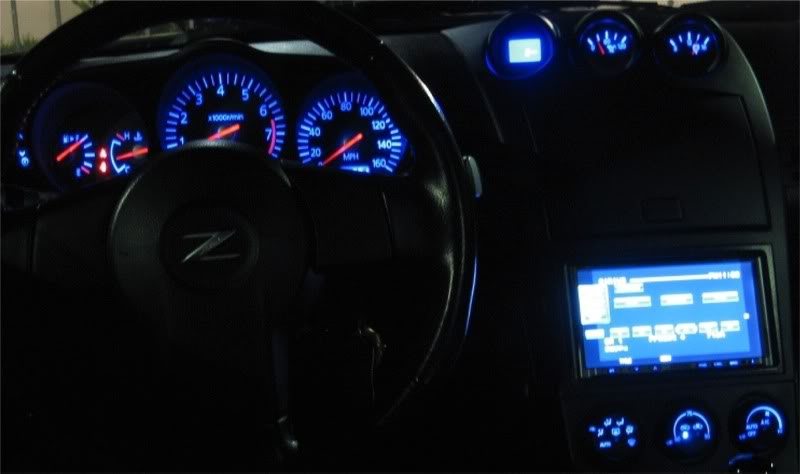
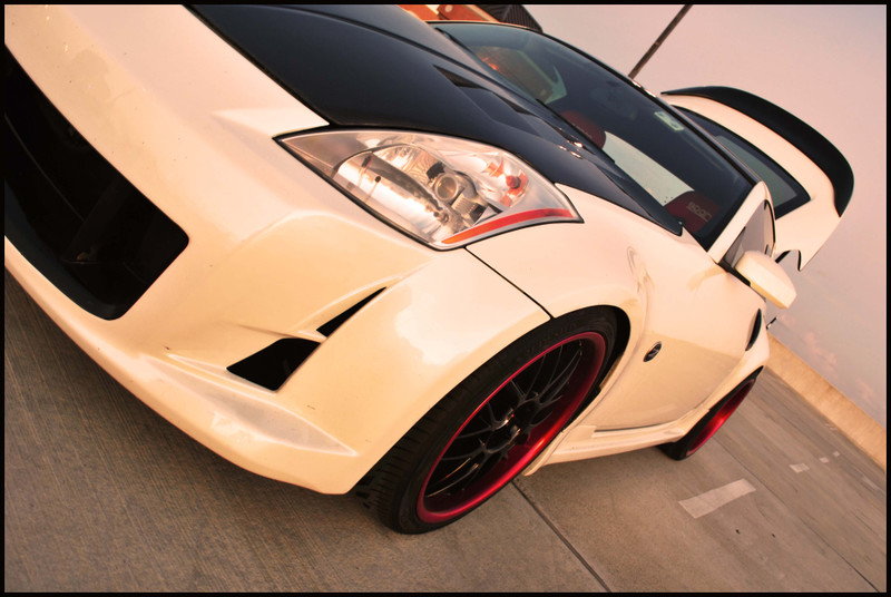
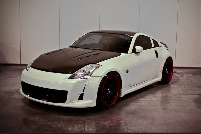
Results of a full blue conversion that does not include the stock radio or the navigation panel
Click the link below for a thread on adding LEDs to the door sill covers and the door handles.
https://my350z.com/forum/exterior-an...ing-green.html
This thread provides information for converting the interior LED lighting for model years 2003 - 2008. The procedure is broken down into sections that are located in separate postings. Larger sections are broken down into parts due to posting size limitations.
NOTE: The sections listed below can be done in any particular order. They may appear a bit disjointed in this list because the information was posted after the work was done. The sequence is different in the PDF and has more of a logical flow to it.
Section 1 - Door handles
Section 2A - AC Controls for 03 - 05
Section 3 - Center Console Gauge Cluster
Section 2B - AC Controls for 06 - 08
Section 4 - Stock Radio - non Bose (procedure should be fairly similar, I just don't have pics to document the Bose unit)
Section 5 - Navigation
Section 6 - Steering Wheel Gauge Cluster (speedo / tach)
Section 7 - Seat Control Rocker Switches
Section 8 - 06 - 08 cup holders
Section 9 - Steering Wheel Controls - NOT PUBLISHED YET - but you will need 7 of the PLCC-2 type LEDs
Some of the postings from others may appear disjointed. This is because the entire thread has been cleaned up and consolidated. Information that others have posted that added creative, technial or procedeural information is retained. If a comment you posted is missing, no offense, the project took a while to complete and document fully and the intent is to consolidate and clean up the info.
For a complete PDF version of this procedure, please send me a PM.
Per the nature of the forum, some of this information was gathered and posted by others and I put my own experience and words to it or I provide a link. A good portion of it is from my own research and experience converting my own car.
My postings are not meant to be the final or complete and total word on the subject and I don't mean to take credit for anything that isn't mine. My intent is to provide a single place for information that was spread out in various threads.
A note about the E-Bay kits. I started with the E-Bay kit and soon determined that the result would be half the interior converted and the other half still stock amber. The E-bay kits only cover the center console 3 gauge cluster and the steering wheel cluster. Also, they do not address how to solder 2 contact LEDs onto the 4 contact locations on the boards.
The parts information in this procedure covers blue, green, red and white LEDs and is subject to change without notice and without any updates to this procedure.
If you decide to get LEDs off e-bay, my experience is that many sellers are located in China / Hong Kong and while they may say "Free Shipping", they mean free to them. They typically have very agressive pricing and I have not been burned but sometimes they ship via US Postal Service cash on delivery without telling you. This can result in a delay while the local post office notifies you that you need to pick up and pay for shipping.
Solder training is not included in this thread, unless someone else adds something. If you cannot solder, it's not recommended that you get into this without lining up a resource. You can check local electronics repair shops, they should be able to do the work for you.
Using the stock gauge faces will not give you the results you see in the pics posted in this thread. The stock gauge faces have an orange backing that cannot be removed. New gauge faces can be purchased from Blackcatcustom.com at http://www.blackcatcustom.com/Nissan%20350Z.htm
Delivery time is typically in the range of 2 weeks.
Differences between automatic and manual transmission as well as the changes in the AC controls between 03-05 and 06-08 are included. Some minor differences in disassembly of door handle controls exist but are not documented here.
A note about brightness. LED lighting in daytime is almost completely washed out with the exception of LCDs (center console trip computer, odometer and gear selection indicator on automatics) and push button LEDs on the AC controls. Some posts in other threads talk about changing out resistors to get better brightness. Forum member Acree (who to my knowledge was one of the first to post LED information) posted that due to a voltage regulator, changing the resistors had no effect. I never got into changing resistors and no information about it is included in this thread. I've experimented with LEDs with higher MCD ratings and these had no effect as well.
A note about diffusing gels. I experimented with diffusing gels and determined that the stock diffusers, after removing the yellow coating (where present), provided the best results but as with all things, different opinions and experiences exist and some information regarding the use of gels is included in this thread and is present elsewhere in the forum.
Tools, Supplies and Costs
Tools
- Soldering / Desoldering Equipment, Tools & Supplies
- #2 Phillips head screwdriver
- Two Vice Grips or Channel Lock pliers or combination of 1 of each - small / medium sized
- Small Flat Blade Screwdriver (tip covered in electrical tape)
- Socket wrench with 6” extension and 10mm socket
- Digital Camera
Supplies
- LEDs in the correct type and quantity as listed in the LED Conversion Parts List shown below
- Soft, clean, cloth towel
- Can of Air Duster
- Glue Stick or other light contact cement or adhesive
- 600 grit sandpaper
- Electrical tape or a two 1" lengths of coolant hose
Costs:
LED’s roughly cost $1.00 each after you include shipping. LED turn signal indicator bulb replacements cost $5.00 each. Depending on the number of LEDs you need, the cost can range roughly between $75 and $125. Gauge faces start at $109.00 and go up from there depending on any customizations you want.
If you are doing this yourself, you can budget $225 - $250 for the costs of all LEDs, gauge faces and shipping and you should be close. If you are not doing this yourself, labor charges can vary widely from professional electronics repair shops to a friend who knows how to solder so labor estimates are not provided here.
Ordering LEDs:
I reference DigiKey http://www.digikey.com as a source for LEDs only because I was able to find part numbers fairly quickly and easily on their site. I am not necessarily endorsing DigiKey nor am I affiliated with them in any way. Another source you could use is Mouser.com http://www.mouser.com though their part numbers are not provided.
Use the tables below to determine which parts and quantities to order. There are six different types of LEDs used. The LEDs used for the AC controls changed after the 2005 model year. Some people like to mix and match colors. If you look at the table carefully, you will see which LEDs are used, how many and where they are used.
Use the “Color QTY For Conversion” column to enter the number of LEDs you will need to order for each color you want to use. B= Blue, G=Green, R=Red and W=White.
Once you know your quantities, use the part numbers to order on line. Keep adding parts and quantities to your order until you are ready to check out. You do not need to setup an account in order to order. Note – if a particular LED is not available from DigiKey, check E-Bay for the type and color you want. If you right click on the image of the table, you can save the JPG and zoom in for easier reading. The links don't work because it is an image. However, the links in the PDF do work.
Replacing resistors is optional and will result in the LEDs shining brighter. Use the table below for information on changing out resistors.
Results of a full blue conversion that does not include the stock radio or the navigation panel
Click the link below for a thread on adding LEDs to the door sill covers and the door handles.
https://my350z.com/forum/exterior-an...ing-green.html
Last edited by lbz; Nov 26, 2009 at 08:46 AM. Reason: Removing all references to selling parts and info and consolidating information.

Registered User
Joined: Nov 2008
Posts: 40
Likes: 0
From: PA
Anyone interested in doing this, I highly recommend contacting sales@lsdiodes.com to get the 3mm blue LEDs referenced in my earlier post. I was surprised that I could not find them anywhere else.
^^^
If it is a regular T1 type led (3mm) then I recommend either Mouser or Oznium. I did the two gauge clusters and I can confirm what Acree said about the resistors change. I changed them out and no difference in output. I could not find anything brighter than 430mcd for a blue PLCC-2 LED, Mouser has some 270mcd ones in stock and Oznium has 200mcd LEDs in stock as well. You sound like you did your homework on this but you might still run into some hick ups so if you need some help just PM me. DO NOT throw away the yellow plastic piece under the main gauge cluster's LCD screen. I did and had to use two layers of blue diffusion gels to get rid of the hot spots. Good luck.
Registered User
Joined: Nov 2008
Posts: 40
Likes: 0
From: PA
Gauge clusters:
a minimum of 26 of the surface mount LED's (same part number as above) EDIT: The LCD in the gauge cluster is barely visible in daylight when using the LCD's referenced for the A/C controls. I'm researching alternatives.
a minimum of 26 of the surface mount LED's (same part number as above) EDIT: The LCD in the gauge cluster is barely visible in daylight when using the LCD's referenced for the A/C controls. I'm researching alternatives.
^^^
I found such an alternative, I just ordered them so I can't tell you for sure if it will work. 720-LBE6SGS2U135Z from Mouser, 1200mcd at 50 amps. I want to change mine out before I recommend them to anyone else. These are PLCC-4, which would be an exact match, looks wise, to the oem amber one. 4 posts, 3 negatives and one positive instead of the two long posts on the PLCC-2, that are used in the doors and ac module. You only need 20 unless you are going to change the red dash neddles to blue as well.
WOW! Very interested to hear about your results with those. I'm assuming you also have or are getting new gauge faces from blackcatcustoms. Is this correct?
I got black with nuetral back ground. I'm wondering if the guy there already does or would do the same thing.
I left all my warning LED's stock, figured it would be best so they stand out. Looks like you are doing the same.
I got black with nuetral back ground. I'm wondering if the guy there already does or would do the same thing.
I left all my warning LED's stock, figured it would be best so they stand out. Looks like you are doing the same.
Registered User
Joined: Nov 2008
Posts: 40
Likes: 0
From: PA
Yeah, that's correct. I got the black and neutral as well, you can see the neutral backing on the main gauge face. I did leave the warnings stock. Blackcatcustoms does whatever you want them to do if you have the patience to wait for it that is. I thought about black face with blue numbers but I went with the neutral in case I felt like changing the LEDs to white or some other color. I'll take some shots shortly of what it looks like during the different outside light conditions now as a reference point and once I get the 1200mcd LEDs I'll take pics then too as a comparison of the two.
Trending Topics
Section 1 - Door Handle Mounted Controls
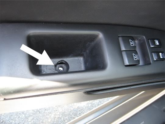
Look in the grip area on the driver's side door handle, there is a small, round plastic cap.
With the tip wrapped in electrical tape to protect against scratches, use the small flat blade screw driver to pop the cap off.
Remove the scew using the #2 Phillips Head screwdriver.
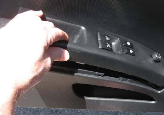
Pull back and up on the door grip assembly and it should dislodge from the door.
Turn the assembly over and disconnect the two wiring connectors by pressing on the connector releases and pulling on the connectors (do not pull on the wires). The larger connector's release is facing the rear of the car while the smaller connector is facing the front of the car.
After the connectors are loose, take the assembly to your work area.
Use the small flat blade to pry the retaining clips loose and remove the control box from the assembly. This may take a bit of back and forth as the clips tend to want to jump back into position. Be careful you dont pry too hard and break a clip.

Use the small flat blade screw driver to remove the control box housing. When the housing is loose on all sides, pull it straight up and off. The control buttons will come up with the housing. You do not need to do anything else with the housing, set it aside.
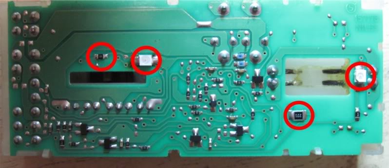
You should now see the circuit board. Replace the LEDs and resistors that are circled. Notice the orientation of the notched corner of each LED. The notch designates the Cathode end. The new LEDs must be replaced in the same orientation. The pic shows the relative location of the notched corner with the word "Notch".
Driver's Side
Passenger Side:
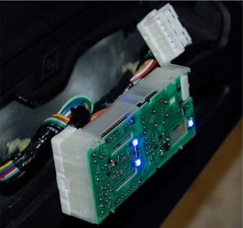
Take the board to the car, connect the large connector and turn the ignition key to ACC. You should see all three LEDs light up.
If the LED's do not light up, double check the orientation and / or resolder and try again.
Once your LEDs are lighting, you are ready to reassemble
Check to make sure that the power window actuators on the circuit board are centered in their respective slots. If they are not centered, move them into the center of the slot.
Snap the control box back into the housing and check the action of the switches. Everything should have the same feel as before.
Snap the control box back into the door handle assembly.
Reconnect the wiring connectos to the door handle assembly and before you snap that back into place on the door, turn the ignition to ACC and check the operation of the window switches, the door locks, the mirror control and the passenger side controls kill switch.
If all the switches are working normally, snap the door handle into place in the door. If not, make sure the wiring connectors from the door are snapped in tight, if still no good, take the assembly apart and confirm the window actuators are centered in their slots.
Insert and tighten the securing screw and replace the plastic cap.
The process for the passenger side door is identical except that there is a slight difference in removing the door handle assembly and there are only two LEDs to replace.
For the procedure on removing the passenger side control box click on the link below. Instructions and pics from that thread will be included in the PDF version but for here, why bother and also want to give credit to the member who posted it. Do not go past the 11th picture.
https://my350z.com/forum/audio-video...r-install.html
Once you have the assembly off, follow the same steps as the driver's side above:
- remove the housing from the assembly by prying the fasteners loose
- remove the control box from the housing
- remove and replace the LEDs (note the location of the notches)
- test by plugging into the wiring harness
NOTE - the drivers' side controls must be connected in order to test the passenger side
- snap the control box into the housing (ensure window actuator is centered)
- snap the housing into the assembly
- reinstall the assembly onto the door
Look in the grip area on the driver's side door handle, there is a small, round plastic cap.
With the tip wrapped in electrical tape to protect against scratches, use the small flat blade screw driver to pop the cap off.
Remove the scew using the #2 Phillips Head screwdriver.
Pull back and up on the door grip assembly and it should dislodge from the door.
Turn the assembly over and disconnect the two wiring connectors by pressing on the connector releases and pulling on the connectors (do not pull on the wires). The larger connector's release is facing the rear of the car while the smaller connector is facing the front of the car.
After the connectors are loose, take the assembly to your work area.
Use the small flat blade to pry the retaining clips loose and remove the control box from the assembly. This may take a bit of back and forth as the clips tend to want to jump back into position. Be careful you dont pry too hard and break a clip.
Use the small flat blade screw driver to remove the control box housing. When the housing is loose on all sides, pull it straight up and off. The control buttons will come up with the housing. You do not need to do anything else with the housing, set it aside.
You should now see the circuit board. Replace the LEDs and resistors that are circled. Notice the orientation of the notched corner of each LED. The notch designates the Cathode end. The new LEDs must be replaced in the same orientation. The pic shows the relative location of the notched corner with the word "Notch".
Driver's Side
Passenger Side:
Take the board to the car, connect the large connector and turn the ignition key to ACC. You should see all three LEDs light up.
If the LED's do not light up, double check the orientation and / or resolder and try again.
Once your LEDs are lighting, you are ready to reassemble
Check to make sure that the power window actuators on the circuit board are centered in their respective slots. If they are not centered, move them into the center of the slot.
Snap the control box back into the housing and check the action of the switches. Everything should have the same feel as before.
Snap the control box back into the door handle assembly.
Reconnect the wiring connectos to the door handle assembly and before you snap that back into place on the door, turn the ignition to ACC and check the operation of the window switches, the door locks, the mirror control and the passenger side controls kill switch.
If all the switches are working normally, snap the door handle into place in the door. If not, make sure the wiring connectors from the door are snapped in tight, if still no good, take the assembly apart and confirm the window actuators are centered in their slots.
Insert and tighten the securing screw and replace the plastic cap.
The process for the passenger side door is identical except that there is a slight difference in removing the door handle assembly and there are only two LEDs to replace.
For the procedure on removing the passenger side control box click on the link below. Instructions and pics from that thread will be included in the PDF version but for here, why bother and also want to give credit to the member who posted it. Do not go past the 11th picture.
https://my350z.com/forum/audio-video...r-install.html
Once you have the assembly off, follow the same steps as the driver's side above:
- remove the housing from the assembly by prying the fasteners loose
- remove the control box from the housing
- remove and replace the LEDs (note the location of the notches)
- test by plugging into the wiring harness
NOTE - the drivers' side controls must be connected in order to test the passenger side
- snap the control box into the housing (ensure window actuator is centered)
- snap the housing into the assembly
- reinstall the assembly onto the door
Last edited by lbz; Nov 26, 2009 at 08:57 AM. Reason: Clean up as part of overall consolidation
Part 2A - AC Controls for 2003 - 2005
This section is for 03 - 05 Model Years. Section 2B covers AC Controls for 2006 - 2008
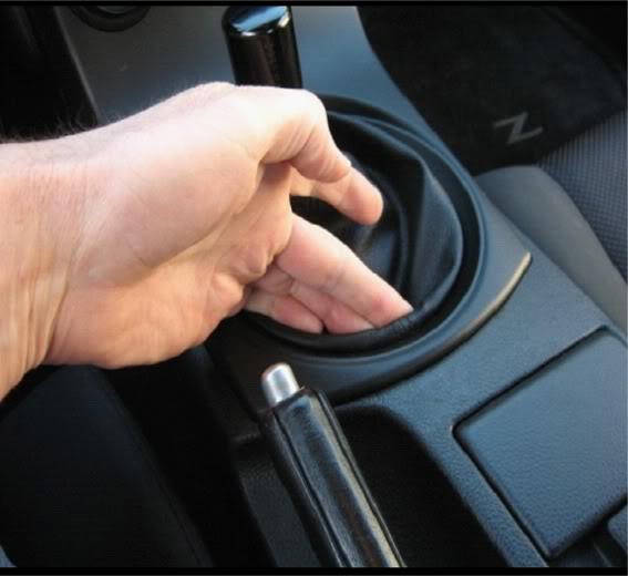
Remove lower finisher by gripping underside of trim ring and pull back
Remove the shift ****
NOTE: You can try to remove the AC Controls without removing the shift **** by turning the lower finisher enough to access the clips in the back that hold the AC Controls enclosure in. If you cannot get to the clips, use the procedure below to remove the shift ****.
NOTE: The instructions below are for removing the shift **** properly to avoid damaging the shifting mechanism. If you have removed your shift **** in the past, skip past the diagrams and pick up at the next picture.
If you have never removed your shift ****, continue through the steps in this section.
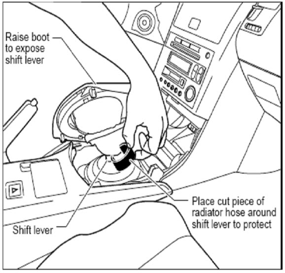
Raise the boot so you can see the base of the shift lever
Cut a piece of radiator hose and place it around the base of the shift lever or wind several layers of electrical tape around the base of the shift lever to protect it as you do the following steps.
Clamp a wrench around the protected base of the shift lever
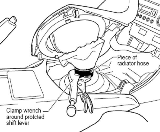
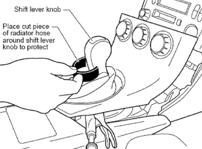
Place a 2nd cut piece of radiator hose or several layers of electrical tape around the base of the shift **** to protect it as you do the following steps.
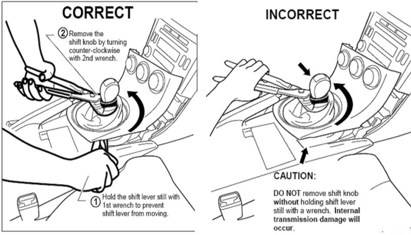
Hold the shift lever still with the 1st wrench at the base of the shift lever to keep it from moving
With the shift lever firmly held in place, remove the shift **** by turning it counter-clockwise with the 2nd wrench.
CAUTION: The transmission will be damaged internally if you do this step wrong. DO NOT remove the shift **** without holding the shift lever still with a wrench. The shift lever must not be allowed to rotate.
See illustrations below for correct vs incorrect methods.
Once the shift **** is loose enough so that it turns without putting torque on the shift lever, unscrew the shift **** by hand the rest of the way and set it aside.
Be careful when moving the lower finisher so you don’t scratch your upper console or the lower finisher.
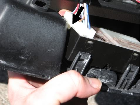
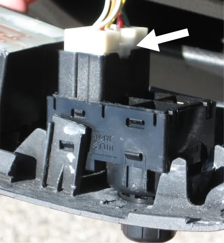
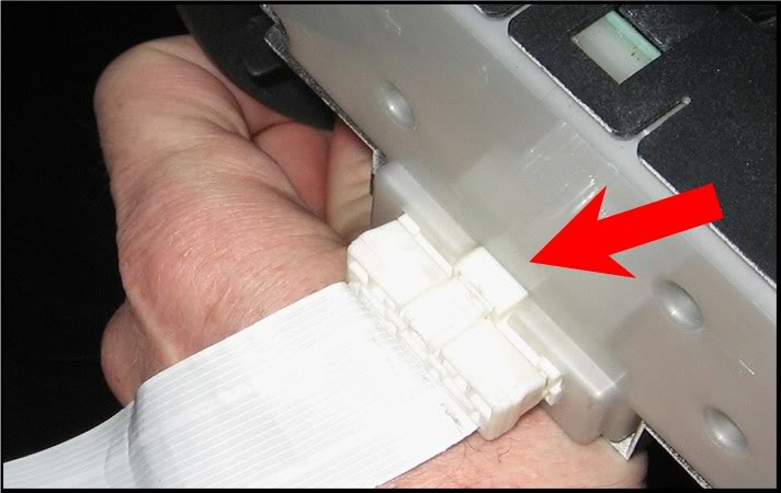
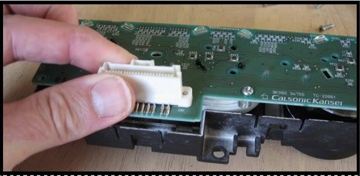
Raise the lower finisher and turn it so you can access the white ribbon cable that plugs into the back of the A/C Control Box.
Press the release tab to remove connector. Pull only on the connector not on the ribbon.
Remove the lower finisher
Remove single screw on the back of the AC control box
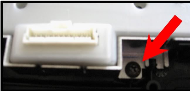
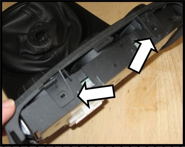
Remove the AC control box by prying the tabs on the top and the sides with a flat blade screw driver.
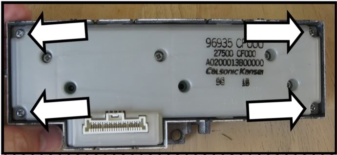
Remove the 4 corner screws from the back cover.
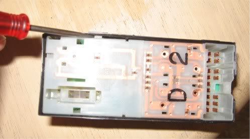
Pry loose the tabs on the top, ends and bottom of the control box and separate the board from the casing.
Remove the remaining screws from the back of the board and pull the ***** off the board
Reference for reassembly
Left **** = Vent Select
Center **** = Temperature Setting
Right **** = Fan Speed
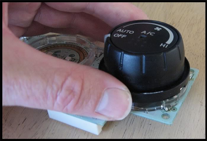
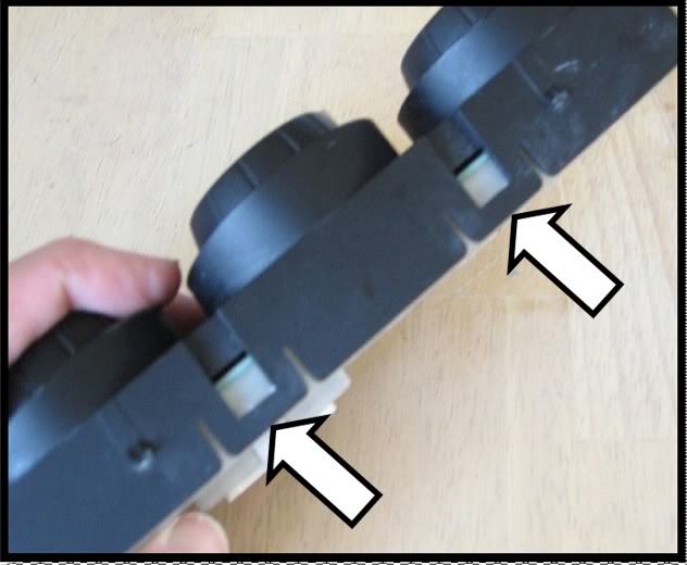
Take the rest of the screws out and gently pull the light tubes off
Ready to begin replacing the LED’s
DONT WIPE OFF THE LUBRICANT ON **** CONTACTS
LEDs have a notch in one corner denoting cathode end. Must be replaced in same position
The right angle LED’s have a mark on the bottom denoting the cathode end.
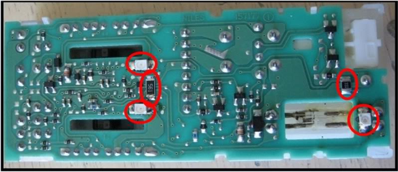
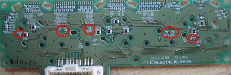
Replace all the LED’s and resistors circled in the pictures below. The resistors are on the back of the board.
Recommend doing LED's and testing in groups. Do the 4 LEDs for a dial first, test it, then move on to the other dials, one at a time, then change out the resistors.
Left set of LEDs
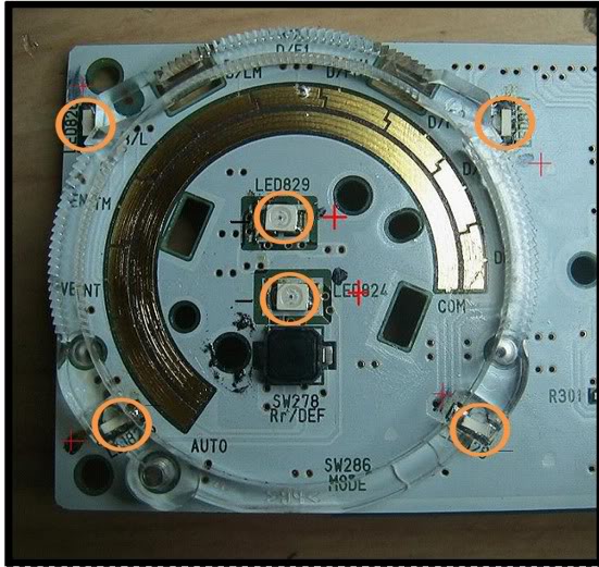
Center set of LEDs
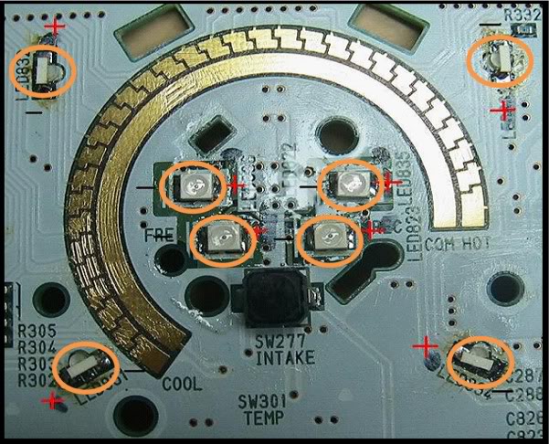
Right set of LEDs
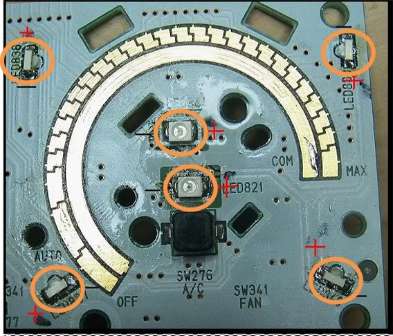
Resistors (R825, R826, R828, R829, R831 and R832)
Clean board with alcohol and swap or brush when finished soldering.
Reassemble in reverse order.
Put the light tubes back on.
Insert the control ***** and put screws in that hold them in place
Put the board & ***** into the front piece
Snap in the rear cover & screw in the 4 corner screws.
Snap the control box into the lower finisher
Put shift boot on, and reconnect the ribbon cable.
Place lower finisher against edge of upper console.
Snap the rear edge of the lower finisher in.
Put shift **** on
If fan comes on at full speed when you start the car, you need to connect the ribbon cable in the back of the AC control box.
Only the center LEDs will show during day time, just the nature of the blue, but at night, lookout, iz very nice.
This section is for 03 - 05 Model Years. Section 2B covers AC Controls for 2006 - 2008
Remove lower finisher by gripping underside of trim ring and pull back
Remove the shift ****
NOTE: You can try to remove the AC Controls without removing the shift **** by turning the lower finisher enough to access the clips in the back that hold the AC Controls enclosure in. If you cannot get to the clips, use the procedure below to remove the shift ****.
NOTE: The instructions below are for removing the shift **** properly to avoid damaging the shifting mechanism. If you have removed your shift **** in the past, skip past the diagrams and pick up at the next picture.
If you have never removed your shift ****, continue through the steps in this section.
Raise the boot so you can see the base of the shift lever
Cut a piece of radiator hose and place it around the base of the shift lever or wind several layers of electrical tape around the base of the shift lever to protect it as you do the following steps.
Clamp a wrench around the protected base of the shift lever
Place a 2nd cut piece of radiator hose or several layers of electrical tape around the base of the shift **** to protect it as you do the following steps.
Hold the shift lever still with the 1st wrench at the base of the shift lever to keep it from moving
With the shift lever firmly held in place, remove the shift **** by turning it counter-clockwise with the 2nd wrench.
CAUTION: The transmission will be damaged internally if you do this step wrong. DO NOT remove the shift **** without holding the shift lever still with a wrench. The shift lever must not be allowed to rotate.
See illustrations below for correct vs incorrect methods.
Once the shift **** is loose enough so that it turns without putting torque on the shift lever, unscrew the shift **** by hand the rest of the way and set it aside.
Be careful when moving the lower finisher so you don’t scratch your upper console or the lower finisher.
Raise the lower finisher and turn it so you can access the white ribbon cable that plugs into the back of the A/C Control Box.
Press the release tab to remove connector. Pull only on the connector not on the ribbon.
Remove the lower finisher
Remove single screw on the back of the AC control box
Remove the AC control box by prying the tabs on the top and the sides with a flat blade screw driver.
Remove the 4 corner screws from the back cover.
Pry loose the tabs on the top, ends and bottom of the control box and separate the board from the casing.
Remove the remaining screws from the back of the board and pull the ***** off the board
Reference for reassembly
Left **** = Vent Select
Center **** = Temperature Setting
Right **** = Fan Speed
Take the rest of the screws out and gently pull the light tubes off
Ready to begin replacing the LED’s
DONT WIPE OFF THE LUBRICANT ON **** CONTACTS
LEDs have a notch in one corner denoting cathode end. Must be replaced in same position
The right angle LED’s have a mark on the bottom denoting the cathode end.
Replace all the LED’s and resistors circled in the pictures below. The resistors are on the back of the board.
Recommend doing LED's and testing in groups. Do the 4 LEDs for a dial first, test it, then move on to the other dials, one at a time, then change out the resistors.
Left set of LEDs
Center set of LEDs
Right set of LEDs
Resistors (R825, R826, R828, R829, R831 and R832)
Clean board with alcohol and swap or brush when finished soldering.
Reassemble in reverse order.
Put the light tubes back on.
Insert the control ***** and put screws in that hold them in place
Put the board & ***** into the front piece
Snap in the rear cover & screw in the 4 corner screws.
Snap the control box into the lower finisher
Put shift boot on, and reconnect the ribbon cable.
Place lower finisher against edge of upper console.
Snap the rear edge of the lower finisher in.
Put shift **** on
If fan comes on at full speed when you start the car, you need to connect the ribbon cable in the back of the AC control box.
Only the center LEDs will show during day time, just the nature of the blue, but at night, lookout, iz very nice.
Last edited by lbz; Nov 26, 2009 at 09:02 AM.
Section 3 - Center Console Gauge Cluster
Some of the pics are not in good focus. I will work on getting those updated with better pics. Posts are limited to 10,000 characters so some of the wording is a bit rough.
For a PDF of this procedure, please PM me, provide your email address and I will email it to you.
You should have a digital camera ready to take reference pictures of the needle positions before you start.
Turn the ignition to the ACC position and take a picture of the center console gauges ase a reference for the needle positions.
Use the section 2 above to remove the lower finisher.
Remove the rubber mat from the cubby, remove the two screws and remove the trim plate

Remove all the screws for the center console – see pictures below.

Remove the screws for the white AC control box to the bracket. The AC Control Box will NOT be coming out, this just makes the process easier.

Cover up the shift lever with a couple old socks.
Pull straight back from the top edge of the upper console to dislodge it from the dash.

Pull out one corner enough to reach back and disconnect the wiring connector. The release tab is facing the windshield.

Pull it out far enough to remove the two screws and remove the cluster. Do not remove the six smaller screws.

Remove the two screws from the front clear cover but leave the cover in place.

Turn it over and pry all the tabs loose, remove the tape and pry up the last tab.
Pull the black piece off the white housing.
Remove the LCD module. Pry loose the two clips holding it in. ]Do not let the tool press against the long contacts. Use the housing below the contacts for leverage. See below.
Bottom Clip
Top Clip

Pull the LCD module out and set it aside.
Remove the needles. Place butter knives or Popsicle sticks on either side of a needle base from opposite directions as shown.
Lightly twist on each side and exert identical pressure on the base. Use even force so the stem does not bend. The needle should come off with little pressure.
Peel the old gauge faces off and set aside
Turn the cluster face down and remove the four screws holding the circuit board in.
Lift the left side board out, then the right and set the housing aside.
Remove all 10 LED’s circled in the picture below.

There are 4 contacts for each LED. There is one positive and three negative with the "top" pair of LEDs being used (one is pos, one is neg).
Your LED’s should not touch the bottom two negative pads. Clean all the solder off all the contacts. Only tin the top negative and positive contacts. See the diagram below.

Solder in the new LEDs in groups and test by connecting the board and turing the key to ACC and confirm the LEDs light up.
Reinstall the boards into the housing and put in the black plastic piece around the wiring connector.
Retrieve the LCD module, pull the LCD out of the white frame and remove the yellow diffuser.
Remove the yellow coating from both sides by wet sanding with 600 grit sand paper, clean off, wipe dry and lay the diffuser back into place.
Re-insert the LCD into the frame. The contact legs must be in their own guide holes. Double check this.
Insert the frame back into the board housing. Once the legs are in their sockets, press down on the edges of the white frame so the two posts go in the holes in the board. Do not press down on the LCD.
As the legs go into the sockets, the LCD will pop up some. Press on the edges of the LCD and then lighly on the center to fully seat the LCD. Check the edges to make sure the LCD is evenly seated.
Plug in the wiring connector, turn the ignition to ACC and check results. the vent system will begin to blow at max because the controls are disconnected.
When ready to proceed, place the housing face up on your work surface.
Remove needle stops from old gauge faces by squeezing the base from the back side of the face and pushing through from back to front.
Use alcohol to remove old adhesive from the housing and ensure the surface is clean and dry.
Be careful when handling gauge faces to avoid creasing or denting.
Test fit new gauge faces – oil pressure in the center and volt meter on the right.
Press the base through the front of the face until it snaps in.

Apply a layer of gluestick where the faces will contact the housing and press the new faces into place, rubbing to remove air bubbles. Remove strands of glue, hair, fibers, etc.
Do not attach the needles to the stems and do not attach the black front trim piece yet.
Take the housing and needles to the car, plug in the wiring connector, turn the key to the RUN position and carefully press the needles onto the stems using your reference picture. The needles should lightly “click” into place. Disconnect and return to work area.
Use the air duster to remove all debris from inside the black trim piece, snap it onto the housing, press all the tabs down, put the tape on and put the two screws back in.
Connect the wiring, turn the ignition to Run and check the needle positions. Turn the key off, disconnect the wiring and reattach the cluster to the center console.
Lean the center console fully back into a rough area of its normal position and reconnect the wiring connector to the gauge cluster.
Firmly press the upper section of the center console back into place.
Re-attach the white A/C control box to the lower bracket
Reinstall all the screws to secure the center console into place
Reinstall the cubby trim plate
Reinstall the cubby rubber mat and close the cubby door. If the cubby door will not stay closed, use the picture in this procedure to ensure the trim plate is positioned correctly.
Remove the sock from the shift lever
Place the lower finisher / shift boot into position and reconnect the A/C ribbon cable to the back of the A/C controls housing.
Place the upper edge of the lower finisher against the lower edge of the upper console so the tabs line up and fit together
Snap the rear edge of the lower finisher into place
Re-attach the shift ****.
Start the engine and confirm your vent system, stereo and gauges are working.
Some of the pics are not in good focus. I will work on getting those updated with better pics. Posts are limited to 10,000 characters so some of the wording is a bit rough.
For a PDF of this procedure, please PM me, provide your email address and I will email it to you.
You should have a digital camera ready to take reference pictures of the needle positions before you start.
Turn the ignition to the ACC position and take a picture of the center console gauges ase a reference for the needle positions.
Use the section 2 above to remove the lower finisher.
Remove the rubber mat from the cubby, remove the two screws and remove the trim plate
Remove all the screws for the center console – see pictures below.
Remove the screws for the white AC control box to the bracket. The AC Control Box will NOT be coming out, this just makes the process easier.
Cover up the shift lever with a couple old socks.
Pull straight back from the top edge of the upper console to dislodge it from the dash.
Pull out one corner enough to reach back and disconnect the wiring connector. The release tab is facing the windshield.
Pull it out far enough to remove the two screws and remove the cluster. Do not remove the six smaller screws.
Remove the two screws from the front clear cover but leave the cover in place.
Turn it over and pry all the tabs loose, remove the tape and pry up the last tab.
Pull the black piece off the white housing.
Remove the LCD module. Pry loose the two clips holding it in. ]Do not let the tool press against the long contacts. Use the housing below the contacts for leverage. See below.
Bottom Clip
Top Clip
Pull the LCD module out and set it aside.
Remove the needles. Place butter knives or Popsicle sticks on either side of a needle base from opposite directions as shown.
Lightly twist on each side and exert identical pressure on the base. Use even force so the stem does not bend. The needle should come off with little pressure.
Peel the old gauge faces off and set aside
Turn the cluster face down and remove the four screws holding the circuit board in.
Lift the left side board out, then the right and set the housing aside.
Remove all 10 LED’s circled in the picture below.
There are 4 contacts for each LED. There is one positive and three negative with the "top" pair of LEDs being used (one is pos, one is neg).
Your LED’s should not touch the bottom two negative pads. Clean all the solder off all the contacts. Only tin the top negative and positive contacts. See the diagram below.
Solder in the new LEDs in groups and test by connecting the board and turing the key to ACC and confirm the LEDs light up.
Reinstall the boards into the housing and put in the black plastic piece around the wiring connector.
Retrieve the LCD module, pull the LCD out of the white frame and remove the yellow diffuser.
Remove the yellow coating from both sides by wet sanding with 600 grit sand paper, clean off, wipe dry and lay the diffuser back into place.
Re-insert the LCD into the frame. The contact legs must be in their own guide holes. Double check this.
Insert the frame back into the board housing. Once the legs are in their sockets, press down on the edges of the white frame so the two posts go in the holes in the board. Do not press down on the LCD.
As the legs go into the sockets, the LCD will pop up some. Press on the edges of the LCD and then lighly on the center to fully seat the LCD. Check the edges to make sure the LCD is evenly seated.
Plug in the wiring connector, turn the ignition to ACC and check results. the vent system will begin to blow at max because the controls are disconnected.
When ready to proceed, place the housing face up on your work surface.
Remove needle stops from old gauge faces by squeezing the base from the back side of the face and pushing through from back to front.
Use alcohol to remove old adhesive from the housing and ensure the surface is clean and dry.
Be careful when handling gauge faces to avoid creasing or denting.
Test fit new gauge faces – oil pressure in the center and volt meter on the right.
Press the base through the front of the face until it snaps in.
Apply a layer of gluestick where the faces will contact the housing and press the new faces into place, rubbing to remove air bubbles. Remove strands of glue, hair, fibers, etc.
Do not attach the needles to the stems and do not attach the black front trim piece yet.
Take the housing and needles to the car, plug in the wiring connector, turn the key to the RUN position and carefully press the needles onto the stems using your reference picture. The needles should lightly “click” into place. Disconnect and return to work area.
Use the air duster to remove all debris from inside the black trim piece, snap it onto the housing, press all the tabs down, put the tape on and put the two screws back in.
Connect the wiring, turn the ignition to Run and check the needle positions. Turn the key off, disconnect the wiring and reattach the cluster to the center console.
Lean the center console fully back into a rough area of its normal position and reconnect the wiring connector to the gauge cluster.
Firmly press the upper section of the center console back into place.
Re-attach the white A/C control box to the lower bracket
Reinstall all the screws to secure the center console into place
Reinstall the cubby trim plate
Reinstall the cubby rubber mat and close the cubby door. If the cubby door will not stay closed, use the picture in this procedure to ensure the trim plate is positioned correctly.
Remove the sock from the shift lever
Place the lower finisher / shift boot into position and reconnect the A/C ribbon cable to the back of the A/C controls housing.
Place the upper edge of the lower finisher against the lower edge of the upper console so the tabs line up and fit together
Snap the rear edge of the lower finisher into place
Re-attach the shift ****.
Start the engine and confirm your vent system, stereo and gauges are working.
Last edited by lbz; Jul 26, 2009 at 01:42 PM. Reason: Replaced reference to using gel with sanding stock diffuser
I actually got best results with the #103 white. The blues did not do as good a job of getting rid of the hot spots.
Also, because the LEDs are much closer to the LCD on the odometer, hot spots are somewhat discernable on the odometer even after using two layers of the #103 white.
I'm still happy with it but it's not perfect.
I'll try to get some decent pics posted in this thread of how it looks at night. Somehow figure a way to get my tripod set up to take a decent blur free pic at night.

Well I bought some of the diffuser gels off egay. I went with the auction that had 4 gels. I went with gels #103 and 111 for my diffuser gels. Also getting #120(red) and #79(blue) for the hell of it. Might change the color of the gauges sometime down the line.
Last edited by brettrr; Jun 9, 2009 at 04:33 PM.
Got around to finishing the climate controls in white. Couldn't find the right angle leds in white either. Did the same thing soldering 1206 side ways. Will post pics sometime tomorrow. I talked to the ebay member about the gels and here is what they said,
"Hi, You can try any of the frost or diffusion gels, but it will take out some intensity. Roscolux #112 may be light enough for you. Thanks for your interest! Kate"
Thought the 112 would be too light so I went will what you used and #111 which to me sounds like the thickest.
Still waiting for my faceplates to get done but will post results of #111 when I get to try them.

Worst is over. The rest are all the PLCC2 type and the four 3mm for the silver buttons.
Yeah, post em up. I assume you mean in place behind the LCD.
Interested in seeing your white as well. With my blue, your white and the green I'll be doing, all I would need is a red and I could add each color pics to the procedure so folks can get an idea of each result.
yeah, the gauge faces seem to take forever.
If you want section 4 before I've got the final version hammered out, PM me.
Well I don't plan on taking the triple gauge apart intill I get my faceplates, but I can post them up with a different light source behing them. I will post up the difference between the gels with the lcd when I get around to taking apart the gauges.
I was planning on doing the stock radio too, so I think that will be the hardest part. So far with absolutley no previous handling of leds thinks aren't going to bad. Not nearly as bad as I thought it would be.
Here is the picture of the climate controls in white.
Tried to get a picture showing the difference between gels #103 and #111 but it wasn't showing well. What I can do is send you(lbz) some in the mail if you wanted to check it out. Just let me know.
Tried to get a picture showing the difference between gels #103 and #111 but it wasn't showing well. What I can do is send you(lbz) some in the mail if you wanted to check it out. Just let me know.

Maybe "gels" is the wrong word for me to use.
Anyway, the 03 - 05 controls might be easier to pull that off with as there is a separate LED for the dial pointer every 90 degrees but with 06 - 08, the LED moves with the dial as you turn it. The only thing that would change color on the 03-05 would be the pointer on the dial.
The dial symbols back lighting is provided by just 2 LEDs and I don't know where the piece of gel would go, it's just not mechanically set up to support the scenario. Best I can figure is you would have a two tone dial...
The pic looks like a permanently colored pattern in the lense that sits over probably white LEDs
Still waiting on my gauge faceplate, so it looks like it will be awhile before I get my conversion done.
So lbz would you say the reversing film is worth it or not?