When you click on links to various merchants on this site and make a purchase, this can result in this site earning a commission. Affiliate programs and affiliations include, but are not limited to, the eBay Partner Network.
well ive been meaning to write this. i didnt have much to work off of so i kind of just went with what i saw and it worked.
what you will need:
wire (something thin, maybe 22gauge idk)
screwdrivers
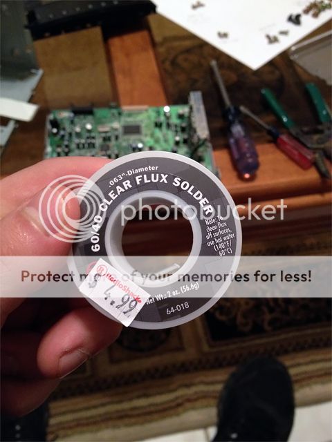
solder and gun
some kind of clippers
drill, bit, tiny cutoff wheel like a dremel (if mounting on the radio)
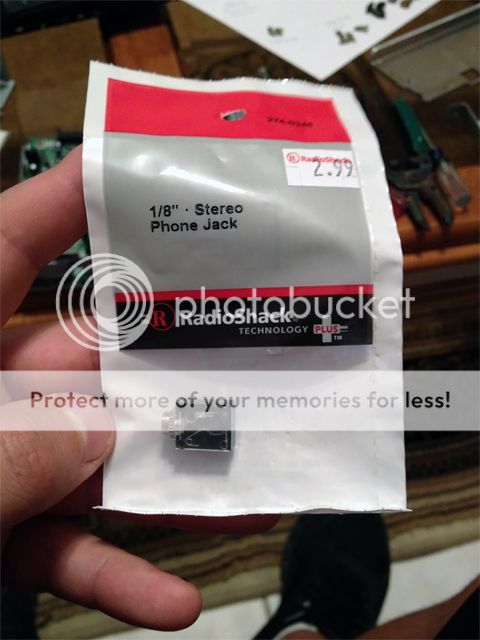
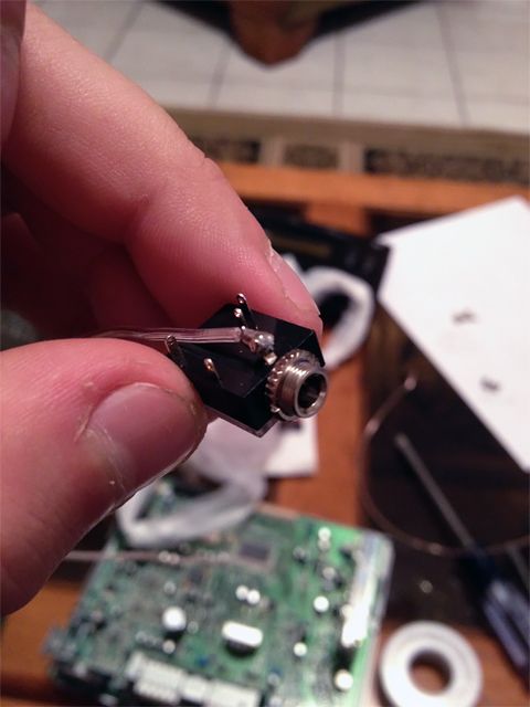
--->1/8" Stereo Phone Jack - P/N 274-0246 from radioshack
it looks like
you will need to find out what radio you have and search the code, mine was a p2515 and this is the site to check http://elektrotanya.com/?q=keres
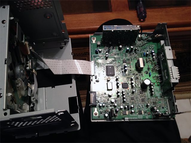
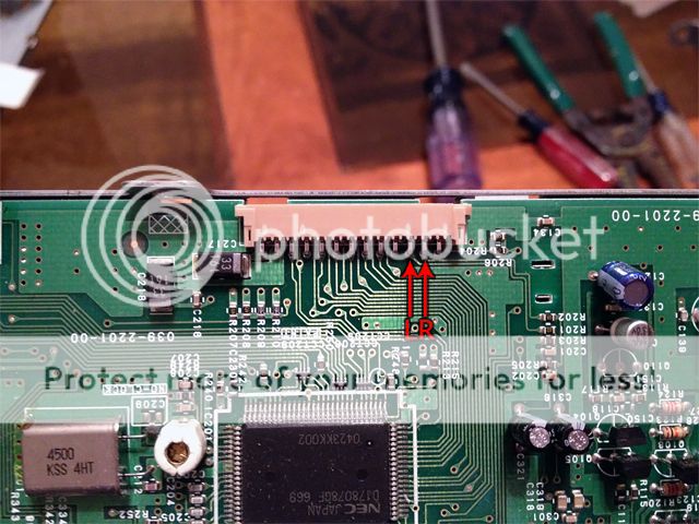
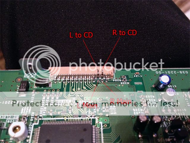
what your looking for is this. you want to see where the pins go from the main board to the cd mechanism, the 2 ive done have both been the 4th and 6th pin. which looks like the 2nd and 3rd on the pins becasue the every other pin is bend under instead of over
it worked on my radio (2007 base) and my friends (2004 enthusiast)
how i drove for the day
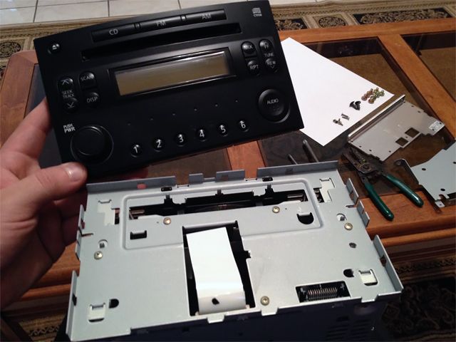
take apart your radio
find these pins, its the white line that leads to the cd mechanism
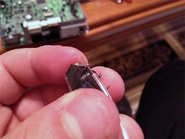
try your best the cut the 2nd and 3rd outside pins in half so you can solder on them, i didnt do the greatest on mine
and dont pull the pin out, i messed up by doing that on one of my pins
Nice writeup especially for those that still want the OEM look. I hope they move it to the DIY section where
members usually look for info like this. Your pics are so clear
Nice write up OP. I'm gonna go ahead and take a shot at this. Drove to radio shack and picked up the headphone jack, soldering wire, speaker wire etc.
I'm going to put the headphone jack in the back of the unit instead though and run a headphone wire threw my center console and have it pop out in the tray between the seats. I'll post pics and keep everyone posted.
Thanks for the writeup, OP. I did this a couple weeks ago, and it turned out brilliantly.
I did this because my CD player doesn't work, forgetting the fact that the CD player needs to work. I was able to fanagle my CD player to work, or atleast figure out there was a CD in there. With the CD in there, the aux port works great.
Got it done last night and it works perfectly. I decided to put the headphone jack in the front plate instead of routing it to the back which was my previous plan. Here are my pics, not trying to thread jack or anything, just hope it can help others. This mod is super easy, just make sure you have a couple hours (I took my time).
The whole mod cost me about 16 bucks. I think it's well worth it. No need to purchase an 80+ dollar aftermarket unit.
Thanks OP
Materials I bought (already have soldering gun). All purchased from the shack.
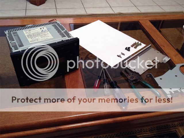
Tools I used. Really only 3. Wire splicers and phillip/flat screwdrivers. Soldering gun too.
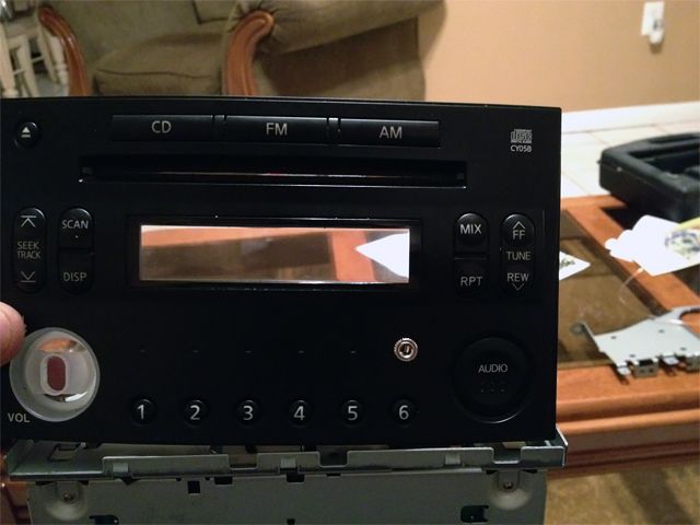
Front face plate snaps right off.
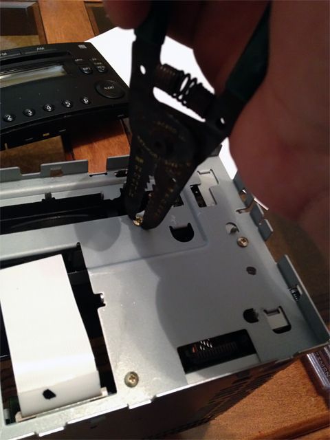
I used the tips of my wire splicer to loosen the screws. Things are dead tight.
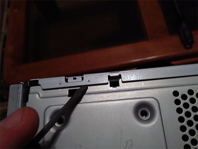
I only removed the main chip frame. Pry it off with a flat head screwdriver. Also, the white ribbon is detachable.
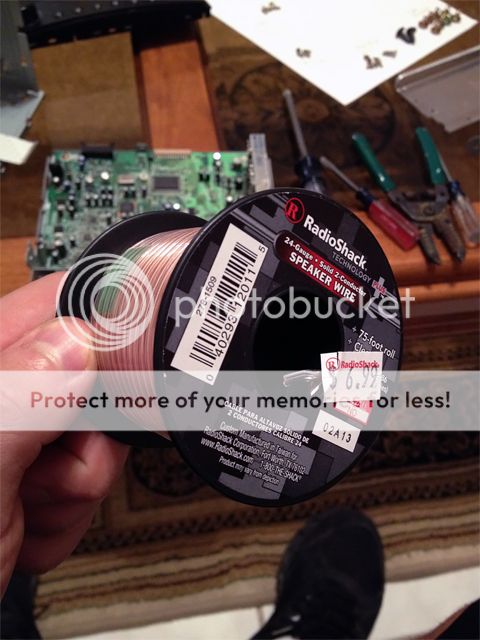
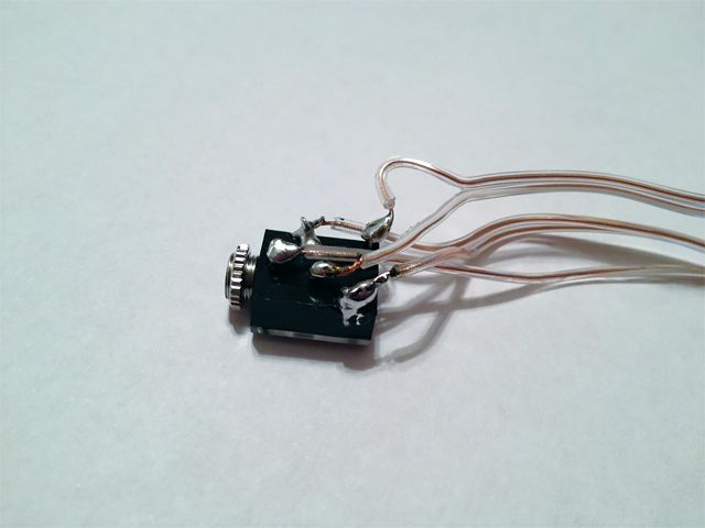
I used 24 gauge speaker wire. Works good. Tied it to the connectors on the headphone jack and soldered.
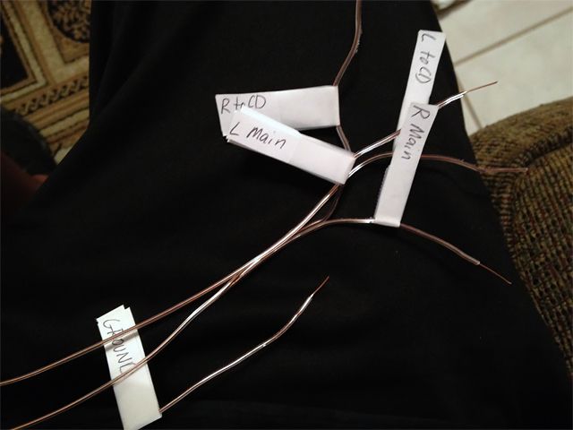
The two pins that need to be cut in half (hardest part imo). I labeled my wires and followed OPs headphone jack diagram. Ground wire can be hooked anywhere to the metal base of the stereo.
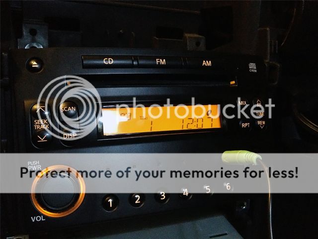
Put it all together and works perfectly. Aux input looks like it comes that way from factory.
Done! I found out that on 3rd picture i need cut 5 and 6 pins (if count from left to right). 5 is for right chanel, 6 is for left chanel, so half of them would go for cd and half of them for headunit.
Made aux in stock bose headunit 2008. If anybody would try the same - you should cut some metal parts ("walls of HU") of headunit, because wire cant be there without it.
Great! Glad you managed to figure it out. I researched a bit, and your model was different. So I compiled some info here for anyone who has the same model as you (Clarion PP-2779L), so anyone knows exactly what to snip.
Hi guys! First of all, shoutout to drvqz33, what an awesome tutorial! I have a question - I do not need CD player, is it enough to snip pins and solder L and R channels to jack only, or does the unit need connection to cd player anyway for some signal? Thx!
Sorry to resurrect an old thread, but after spending several hours searching, this is the only post I can find in any forum that shows how to wire to the CD input, which I would like to do for highest quality.
Is it necessary to cut the two pins? I assume this is in case there is a CD playing in the unit, to not overload the amp with the additional AUX signal - but what if I were to simply play a �silent CD� at all times - would it still be necessary to cut the pins?
Also, to confirm, if the pins need to be cut, the AUX cable should be soldered to the side of the pins going to �main�, not the ones going to CD, correct?
N�o consigo visualizar as fotos amigo ! Poderia me enviar o diagrama para ligar
Originally Posted by drvqz33
Got it done last night and it works perfectly. I decided to put the headphone jack in the front plate instead of routing it to the back which was my previous plan. Here are my pics, not trying to thread jack or anything, just hope it can help others. This mod is super easy, just make sure you have a couple hours (I took my time).
The whole mod cost me about 16 bucks. I think it's well worth it. No need to purchase an 80+ dollar aftermarket unit.
Thanks OP
Materials I bought (already have soldering gun). All purchased from the shack.
Tools I used. Really only 3. Wire splicers and phillip/flat screwdrivers. Soldering gun too.
Front face plate snaps right off.
I used the tips of my wire splicer to loosen the screws. Things are dead tight.
I only removed the main chip frame. Pry it off with a flat head screwdriver. Also, the white ribbon is detachable.
I used 24 gauge speaker wire. Works good. Tied it to the connectors on the headphone jack and soldered.
The two pins that need to be cut in half (hardest part imo). I labeled my wires and followed OPs headphone jack diagram. Ground wire can be hooked anywhere to the metal base of the stereo.
Put it all together and works perfectly. Aux input looks like it comes that way from factory.
n�o consigo visualizar as fotos e onde ligar os fios el�tricos
tem o diagrama utilizado?