
Oil Catch Can Connection question

Originally Posted by Snow-G
Attachment 166312 From here to the crank vent yes? Where is the vent from the back of engine you speak of?
Yes thats the place. Look at my before and after picture for that same peice, its in the lower right section of each picture.
After a full night's sleep (if you call 4.5 hours full) my setup is a little diffrent than your, but just slighlty. There is a T-off that goes from a main vacc line to the rear of rocker pannel to the crank case and into the suction pipe pick off. This stabalizes the idle for the JWT S1 cams. So I was not fully correct when refrencing your set up.
After looking at the design. You may not need the valve cover lines picked off to the catch can when your TT. Each of the lines in the valve covers that make their way up to the lower plenum pass through a PCV valve first. Which means air flows from the valve cover to the plenum under vaccuum. But it looks like the factory intake pickoff goes to the back of the left bank valve cover. This means you get oil contamination from that line going from that line to the pick off.
Here is the interesting part. Since the valve cover lines that enter the lower plenum have PCV's to prevent them from pressurizing, under boost they close. That means at high revs all the oily gasses go from the right bank, stabalizing line, left line, to the pick off on your suction pipe. All that flow goes to yor suction pipe pick off.
If you want refrence pages in the service manual: EM 15 & EM 38. This shows clearly the pick off and where they go. So it still remains, the best place to put the catch can is inline with the sucktion pipe pickoff other wise you are only scavanging part of the time oposed to all the time.

Originally Posted by Snow-G
This guy here right? Any reason the stock line to the intake makes that weird loop?
Attachment 166543
Attachment 166543
Yep thats the guy right there. Some guys disconect that all together but you get an oily smell from the venting. If you do that then put a breather filter on there to keep crap out out of your oil. But yes thats the bit that goes to the intake.
The reason why it does that is to have all metered air flowing into the TB. If it bypasses the TB the air is unmetered and will cause issues. If you have a TT then it may be best if you dont disconect it, your pick off at the suction pipe becomes an inlet and is just another filter to worry about.
Originally Posted by Snow-G
Cool thanks, I thought that was the one you were talking about. Got a little confused with rear of engine, crank thing. 
Yeah, I corrected my self earlier when I started digging in the service manual and my pictures and documents because my set up is alittle diffrent due to the S1's. Sorry for the confusion.

Ok, got it connected/installed. Given the tight plumbing of the JWT TT kit, I had to remove a lot of piping to get to the ones you showed, punish_her, but I got it in there. Took it for a test drive, and there were no vacuum leaks, so thats good. Now to see how much oil it collects.
Thanks for the help, guys!
Dave
Thanks for the help, guys!
Dave
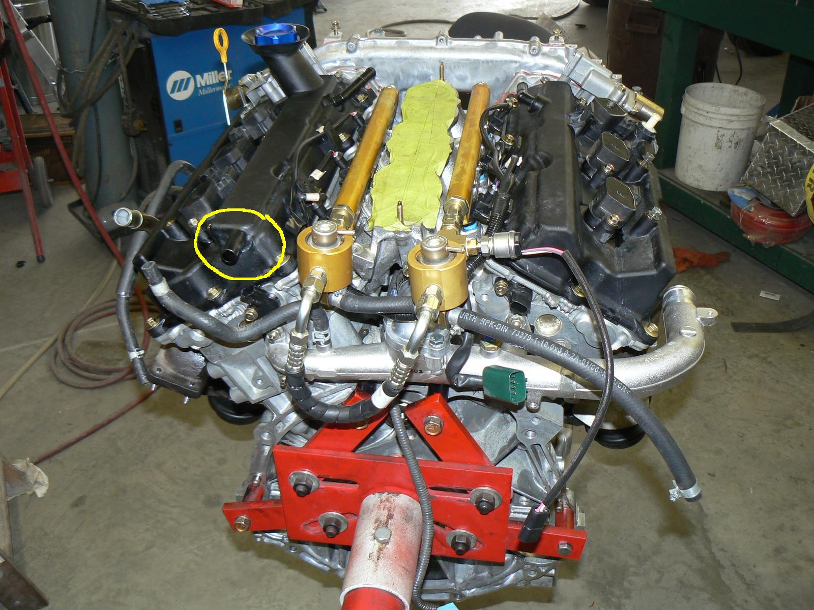
Im glad I got this question asked inadvertantly! I was told by many people that it doesnt matter which side to put the can on. This connection makes more sense, I was gonna just route more line to the drivers side. Thanks again for the input Punish-her.
No sweat man. One thing you may try, the valve covers have the outlets. Under a vacuum it wants to suck into the manifold. Well if your FI, you can cap the lower plenum lines and have every thing route to the suction tube pickoff. That should eliminate almost all the oil vent gases into the manifold.
")

Hmm so, if we are FI, we just attach one side of the catch can to that port on the crank case on the back drivers side, and then where does the other end go? A bit confused, not the place on the plenum where the tube originally led to?...
Look at post 22, that is where you connect your catch can line. Air flows from the plenum, through the right then left valve covers, finaly comming out the port circled in post 22. That connects to the catch can and the other line is connected to the pick-off on your suction pipe shown in post 20. On your Turbo setup the hose from the pick-off is connected directly to the rear valve cover vent. That allows oil vapor to flow into your intake system. The goal is to put a catch can in line with that routing to expell the oil droplets that would make its way into the intake from the suction. The vast majority of the oil vapor in the intake system originates there.
The crank-case routing was to stabalize my idle due to my S1 cams. I explained that early and is unique to my setup.
The crank-case routing was to stabalize my idle due to my S1 cams. I explained that early and is unique to my setup.
Hmm and this is the same for an APS Turbo setup? i dont quite remember any pick off on my intake... :0/ but Im not looking at my setup right now.
Is snow's post not relevant to FI? As it seems to be completely different from what you described.
Is snow's post not relevant to FI? As it seems to be completely different from what you described.
Oooh i see now on the diagram, ok I get it, so I basically put the catch can in the place of the existing tube which runs between the back drivers side crank case and the intake.
Thank you for your help.
Thank you for your help.
Last edited by jining; Dec 4, 2007 at 02:24 AM.
Well... I got a catch can for christmas but... I thought it was 9mm.. not 15mm so it doesnt fit! Damnit.. any point in putting a catch can in the front plenum pcv valve or is that just pointless to run 2 catch cans? 
Last edited by jining; Dec 27, 2007 at 04:48 PM.
Hmmmm.... well I installed the 9mm can, since I got it as a gift I cant really return it, as I have no reciepts :0(....
Maybe I can just put a breather for the rear crank case and plug the pickoff? What would you suggest? Probably not a good idea to T the rear crank case into this current catch can eh? One would think the 9mm catch can would restrict what used to be a 15mm.
Maybe I can just put a breather for the rear crank case and plug the pickoff? What would you suggest? Probably not a good idea to T the rear crank case into this current catch can eh? One would think the 9mm catch can would restrict what used to be a 15mm.


Thread
Thread Starter
Forum
Replies
Last Post