
Oil Catch Can Connection question


Ok, maybe I am stupid, or my reading comprehension skills are subpar today, but I have read a multitude of the oil catch can threads, and I can not, for the life of me, figure out how to connect it.
My oil catch can is the greddy, it has two ports, and from what I agther, at least one of those ports needs to be connected to a spot that is always under vaccuum. This is important to note, because I have a JWT TT kit on my G35, and obviously, the intake manifold is not always under vaccuum. So, do I connect one (or both) of the ports to the intake prior to the turbos, after the turbos, but before the intercoolers, after the intercoolers, etc... (obviously, if I connected it after the turbos, and it required constant vaccuum, I would need some sort of check valve)
Assuming I have the one port connected properly, where does the other port go? Do they both always need vaccuum?
If someone can lay this out step by step, I would appreciate it. And, as I said, I have read a number of the threads on this, and I am still confused, so don't point me to one of those threads.
Thanks
Dave

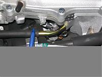
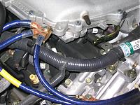
Bro, there is a PCV valve on the pass side valve cover that has a short line running to the plenum. This is where you need to connect the catch can lines. You may need to run out and get more line depending on what was included. After removing the old line, attach one of the lines to the PCV and run it to the can. Then take the other line and attach to the plenum port(the right angle brass looking one) line and run it to the can. Your thinking to hard about it....here is a pic.

ok here you go...
There should be a line that goes from the crankcase to your intake section of your TT. Probably on the right side as you look at it. You pull that off, run a coupler to one of the nozzels on the catch can. Run another line from the other nozzel to the same place that other line was connected. Its always under vaccume and thats where you get the most oil vapor concentration because of the cavitation of the oil and heat. It makes that environment more suseptable to saturation. That goes directly to the suction side of your turbo.
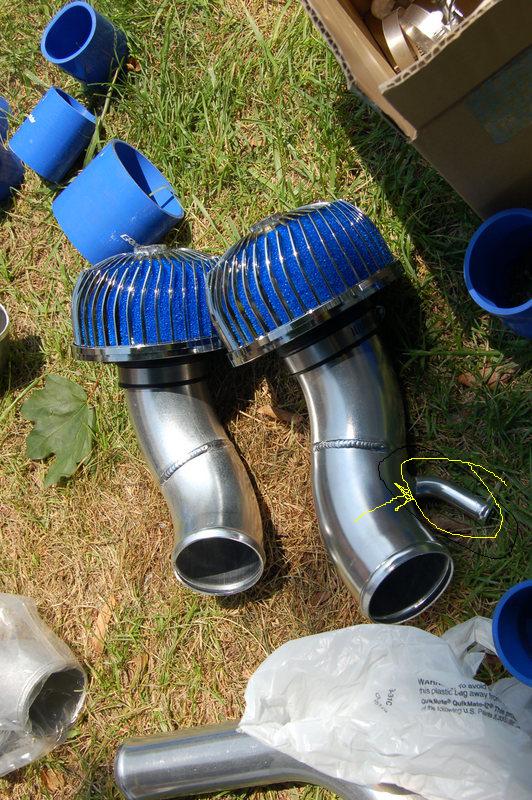
This should give you some idea of how its routed. Frame right, you follow the filter to the suction tube then you come to a 1" pick off. You see the clear line going to the can then pack out. That goes over to the side where it connects to the crank case vent.
If you can get me a good pic of your engine bay I can take a look and see where it is if you can find it right off.
Oh yeah, you can go to the parts store in the heater hose section and get a heater hose barbed coupler and some small hose clamps.
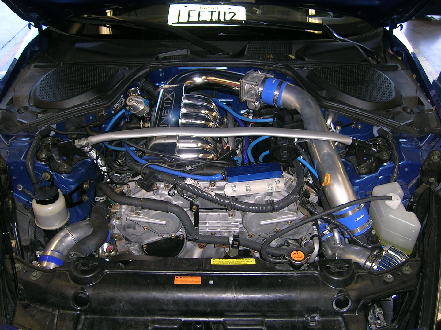
EDIT: yeah yeah no hating on the engine bay, it looks WAY diffrent now. No SSV, no catch can, working on relocating the coolant expansion chamber, vac manifold is moved, Koyo Rad fills up most of the area infront of the engine. Working on getting a set of lingenfelter oil air seperators (recomended for over 500hp due to air flow)
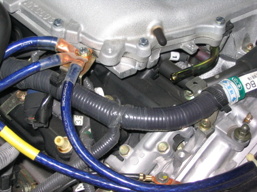
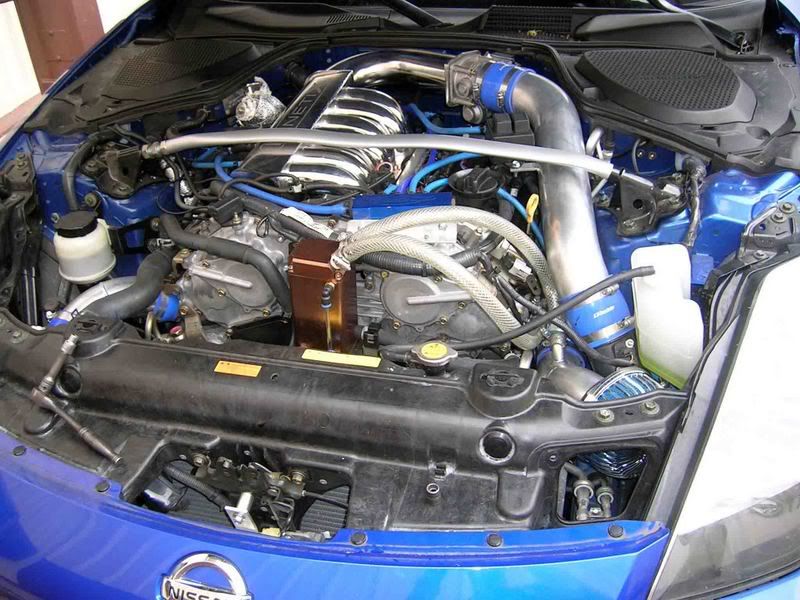
EDIT EDIT: Here is a before pic I came accross you can see the line and where it's hooked up before the catch can install.
yeah its a little big but its midnight here and Im looking in a service manual, dont realy feal like resizing it. Besides take what you get and be happy :P J/K
There should be a line that goes from the crankcase to your intake section of your TT. Probably on the right side as you look at it. You pull that off, run a coupler to one of the nozzels on the catch can. Run another line from the other nozzel to the same place that other line was connected. Its always under vaccume and thats where you get the most oil vapor concentration because of the cavitation of the oil and heat. It makes that environment more suseptable to saturation. That goes directly to the suction side of your turbo.
This should give you some idea of how its routed. Frame right, you follow the filter to the suction tube then you come to a 1" pick off. You see the clear line going to the can then pack out. That goes over to the side where it connects to the crank case vent.
If you can get me a good pic of your engine bay I can take a look and see where it is if you can find it right off.
Oh yeah, you can go to the parts store in the heater hose section and get a heater hose barbed coupler and some small hose clamps.
EDIT: yeah yeah no hating on the engine bay, it looks WAY diffrent now. No SSV, no catch can, working on relocating the coolant expansion chamber, vac manifold is moved, Koyo Rad fills up most of the area infront of the engine. Working on getting a set of lingenfelter oil air seperators (recomended for over 500hp due to air flow)
EDIT EDIT: Here is a before pic I came accross you can see the line and where it's hooked up before the catch can install.
yeah its a little big but its midnight here and Im looking in a service manual, dont realy feal like resizing it. Besides take what you get and be happy :P J/K
Last edited by punish_her; Oct 28, 2007 at 08:38 AM.
Trending Topics
Originally Posted by Snow-G
Bro, there is a PCV valve on the pass side valve cover that has a short line running to the plenum. This is where you need to connect the catch can lines. You may need to run out and get more line depending on what was included. After removing the old line, attach one of the lines to the PCV and run it to the can. Then take the other line and attach to the plenum port(the right angle brass looking one) line and run it to the can. Your thinking to hard about it....here is a pic.
Attachment 166275
Attachment 166276
Attachment 166275
Attachment 166276
The thing about that location is its too far back in the system. You dont pick up much oil there because the PCV closes under pressure. Since he is TT, he will be under pressure and the suction that comes into play through the suction tube on the turbo pulls WAY more vaporized oil in than what your getting on the wrong side of that PCV.
Comming off the crankcase into your intake is the easiest way to remove the most oil vapor 100% of the time. Since you have PCV there your catch can is only under vacuum thus making it less effective for oil removal and more of a show deal. Thats even a less desirable place for NA cars that dont see boos for the same reason. During the time that valve is open and you are getting some air flow, you are only clearing a small percentage of the air. Think trying to drink from a water hose by putting a straw in the stream.
Also with the can in your location you have an EVEN bigger catch can to worry about called the intercooler. Putting the can between the cranck case and the suction tube removes the oil before it even enters the system. Therefore inline with the crankcase line is a safer and more effective location for a TT or NA catch can. No PCV needed.
Last edited by punish_her; Oct 28, 2007 at 07:50 AM.
Originally Posted by Snow-G
punish_her...
Do you get more oil from drivers side than pass? I haven't tried drivers yet, but I'm thinking of getting more line to hook both sides up.
Do you get more oil from drivers side than pass? I haven't tried drivers yet, but I'm thinking of getting more line to hook both sides up.
Last edited by punish_her; Oct 28, 2007 at 07:55 AM.
I also have TT's and after install of my can there was a significat drop in oil form the intake tube and upper/lower plenum. The last time I drained the can there was very little vapor in the intake. That is the only reason Im thinking of running extra lines to driver side.
Edit* the crank case makes sense, where is the vent line for it?
Edit* the crank case makes sense, where is the vent line for it?
Last edited by Snow-G; Oct 28, 2007 at 08:05 AM.
Originally Posted by Snow-G
I also have TT's and after install of my can there was a significat drop in oil form the intake tube and upper/lower plenum. The last time I drained the can there was very little vapor in the intake. That is the only reason Im thinking of running extra lines to driver side.
I bet if you chang it up to the crank case your gonna see more oil. The oil is still getting through. More so now that your cranks case line is under a signifacant amount of vaccuum compared to what it was before.
Again, both side....
Your just putting 2 straws in the water hose now but alot is still getting by. Think of the catch can as a 55 gallon drum, you spray the water over the 2 straws and the little bit collected runs into the barrel. Putting the catch can inline with the crank case vent your putting the hose directly in the drum.
Again this realy doesnt solve your secondary problem oil build up in the IC either. That reduces its efficiency quite a bit.
Originally Posted by Snow-G
Vent line for crank case is where?
It comes from the back of your engine to the front arround the side, and in most kits; has a pick off that creats the needed vaccuum in the crank case. Let me look in the service manual to give you a better visual refrence.
Originally Posted by punish_her
Again, both side....
Your just putting 2 straws in the water hose now but alot is still getting by. Think of the catch can as a 55 gallon drum, you spray the water over the 2 straws and the little bit collected runs into the barrel. Putting the catch can inline with the crank case vent your putting the hose directly in the drum.
Again this realy doesnt solve your secondary problem oil build up in the IC either. That reduces its efficiency quite a bit.
Your just putting 2 straws in the water hose now but alot is still getting by. Think of the catch can as a 55 gallon drum, you spray the water over the 2 straws and the little bit collected runs into the barrel. Putting the catch can inline with the crank case vent your putting the hose directly in the drum.
Again this realy doesnt solve your secondary problem oil build up in the IC either. That reduces its efficiency quite a bit.
Edit* lol>tag ur it.
Originally Posted by punish_her
It comes from the back of your engine to the front arround the side, and in most kits; has a pick off that creats the needed vaccuum in the crank case. Let me look in the service manual to give you a better visual refrence.

I also came accross other places you might think of lookin if you want to suck oil out. The valve covers each has a vac line that runs to the intake or the lower manifold collector. On the right bank its in the front, left bank the rear.
You get all 3 (both covers and crank case) and you got all your oil inputs into the intake. The trouble with that is getting all the line back to where they need to be.
EDIT: Cant seem to find the refrence but the main thing is there are main pickoffs that go to the intake and lower manifolds (after looking the 2 you have picturs of) that originate from places that contain oil. Looking at the diagram there are several vaccuum feeds into the manifold. Those are the places you need to scavange from. The most important one is the one that goes to your suction tube. Thats the one that has the biggest effect since thats where the oil come in hits your copressor turbin (coating it up) then gets pushed into your inter cooler (filling it up) then into your manifold.
I would say the biggest beast you want to tackle that will give you the most bang for your buck is the one going into the pick of of your suction tube. Get me a good quality pic and I can probably find where you need to hook up your can.
EDIT EDIT: Looked in the Greddy install guide i have in PDF and I didnt see any refrence to the suction pipe pick off and where it goes. Im thinking I have a little diffrent setup because of my S1 cams. Again, reguardless of which kit sends what lines where, the main one you need goes to the suction pipe of your kit. Thats the one that prevents alot of the misc. problems.
Last edited by punish_her; Oct 28, 2007 at 09:01 AM.
Originally Posted by punish_her
I also came accross other places you might think of lookin if you want to suck oil out. The valve covers each has a vac line that runs to the intake or the lower manifold collector. On the right bank its in the front, left bank the rear.
You get all 3 (both covers and crank case) and you got all your oil inputs into the intake. The trouble with that is getting all the line back to where they need to be.
EDIT: Cant seem to find the refrence but the main thing is there are main pickoffs that go to the intake and lower manifolds (after looking the 2 you have picturs of) that originate from places that contain oil. Looking at the diagram there are several vaccuum feeds into the manifold. Those are the places you need to scavange from. The most important one is the one that goes to your suction tube. Thats the one that has the biggest effect since thats where the oil come in hits your copressor turbin (coating it up) then gets pushed into your inter cooler (filling it up) then into your manifold.
I would say the biggest beast you want to tackle that will give you the most bang for your buck is the one going into the pick of of your suction tube. Get me a good quality pic and I can probably find where you need to hook up your can.
EDIT EDIT: Looked in the Greddy install guide i have in PDF and I didnt see any refrence to the suction pipe pick off and where it goes. Im thinking I have a little diffrent setup because of my S1 cams. Again, reguardless of which kit sends what lines where, the main one you need goes to the suction pipe of your kit. Thats the one that prevents alot of the misc. problems.
You get all 3 (both covers and crank case) and you got all your oil inputs into the intake. The trouble with that is getting all the line back to where they need to be.
EDIT: Cant seem to find the refrence but the main thing is there are main pickoffs that go to the intake and lower manifolds (after looking the 2 you have picturs of) that originate from places that contain oil. Looking at the diagram there are several vaccuum feeds into the manifold. Those are the places you need to scavange from. The most important one is the one that goes to your suction tube. Thats the one that has the biggest effect since thats where the oil come in hits your copressor turbin (coating it up) then gets pushed into your inter cooler (filling it up) then into your manifold.
I would say the biggest beast you want to tackle that will give you the most bang for your buck is the one going into the pick of of your suction tube. Get me a good quality pic and I can probably find where you need to hook up your can.
EDIT EDIT: Looked in the Greddy install guide i have in PDF and I didnt see any refrence to the suction pipe pick off and where it goes. Im thinking I have a little diffrent setup because of my S1 cams. Again, reguardless of which kit sends what lines where, the main one you need goes to the suction pipe of your kit. Thats the one that prevents alot of the misc. problems.
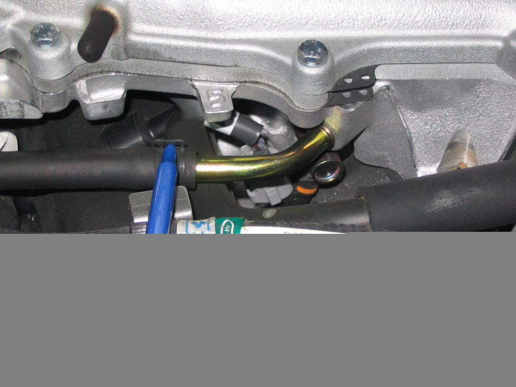
 From here to the crank vent yes? Where is the vent from the back of engine you speak of?