
Relocated Vacuum Sources - Overboost?


the other thing to remember is that if you do relocate the WG reference to a location that is pre-intercooler, you will have a higher reference pressure as compared to the other pressure signal that is going to the yhour EBC----and then into the top ports of your wastegates.........therefore, requiring you to make changes to your EBC programming, too. just some food for thought.
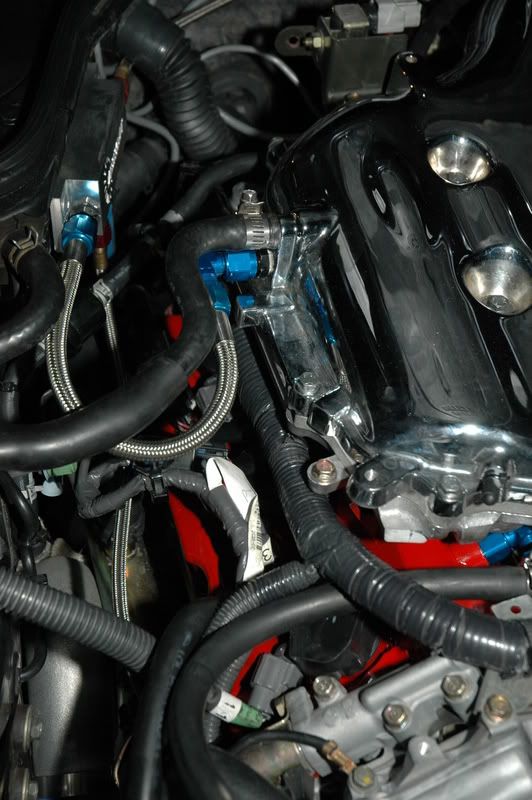
here's a pic of where I tapped my manifold for vacuum/pressure source:

hehe I found that thread with your picture and will be doing that.
Just not as fancy
So you're saying it's OK to leave the WG reference on the manifold? Or should I move it before the throttle body?
I ask because Tial says the source should be before the throttle plate because you dont want your WG going into Vacuum.
What do you have connected to your vacuum manifold?
Last edited by RandomHer0; Apr 13, 2010 at 06:22 AM.

ideally, the wastegate shouldn't see vacuum, but your wastegate is going to see vacuum on the top ports too unless you move those vacuum lines too.
just about every greddy kit on these forums has the wastegates seeing vacuum. I'm sure someone has drilled and tapped the compressor scroll, but I haven't seen it on a greddy kit yet. I'll go by my own experience and over 30,000 miles of boosted action with my wastegates seeing vacuum while cruising and idling....and no wastegate issues. In short, I wouldn't worry about it.
just about every greddy kit on these forums has the wastegates seeing vacuum. I'm sure someone has drilled and tapped the compressor scroll, but I haven't seen it on a greddy kit yet. I'll go by my own experience and over 30,000 miles of boosted action with my wastegates seeing vacuum while cruising and idling....and no wastegate issues. In short, I wouldn't worry about it.
^^ Yeah, something made me realize that last night.
I tapped my plenum like you did, same place, re-routed the vacuum source to the vacuum manifold, then realized, although I was using the AAM spacer last year....it still sits behind the throttle body, not in front of it.
So really...nothing has changed from that perspective. I've been running the Wastegates like that (in vacuum/boost) for 2+ years now and only now have a boost issue. Most likely from all the changes I made.
Im getting some tuning done this weekend, I was hitting 13lbs last night!
Last edited by RandomHer0; Apr 14, 2010 at 04:12 AM.


This is what I did on my charge piping for my WG signal:
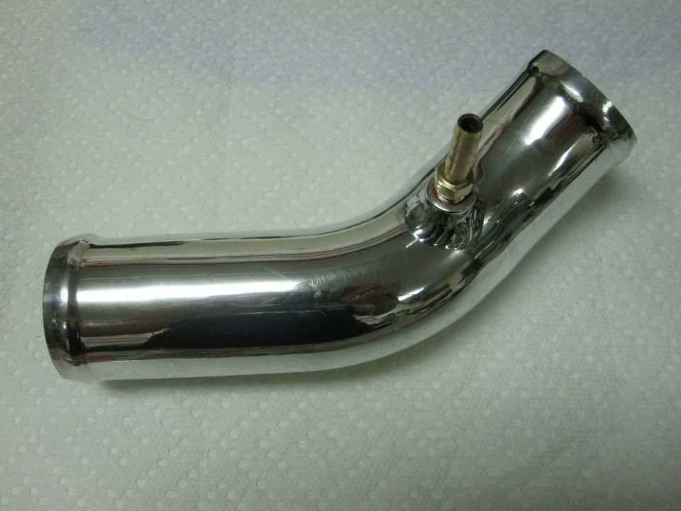
If you can't easily weld (not everyone has str8dum1's skills or equipment) I would rather take out a section of piping that's easy to get to and drill and tap a 1/8" npt port, put in a small nipple. If the piping is aluminum and you're worried about it, add some jb weld around it.
The cast aluminum in the IC somewhere is also a good place to drill and tap if you can clean out the shavings or catch them (near the entry or exit piping). Or if the charge pipe is steel, it should hold fine with just a couple threads.
Last edited by rcdash; Apr 14, 2010 at 02:47 PM.
Do you have a picture of this installed in your engine bay? Im trying to picture which piece it is, I assume its not a greddy kit.
 In fact, that is where the JWT kit instructions call for it to be sourced (and they provide a 1/8" npt port right there). They provide nipples on each pipe leading away from the compressor also for testing and troubleshooting.
Thanks, I did some more searching to see what other kits do and found the powerlabs kit does it on the hot side of the intercooler. Closer to the compressor housing I guess since there would be a drop in pressure going through the intercooler.
Seems like it could almost go anywhere before the TB.
Seems like it could almost go anywhere before the TB.
Theres so much "info" regarding this topic on the net lol
Apparently hotside is the place to be for wastegates.
Its funny the Greddy instructions actually say to use the instake manifold.
Weird.
Apparently hotside is the place to be for wastegates.
Its funny the Greddy instructions actually say to use the instake manifold.
Weird.
Last edited by RandomHer0; Apr 15, 2010 at 07:17 AM.
No anywhere before the TB is correct. There are some advantages to doing it after the merge of the two turbos I think. After all most folks use one solenoid with one boost reference to regulate *both* wastegates. Why not use the average of the compressor outlets (though they should be pretty close anyway to each other). The disadvantage is that there is a slight pressure drop over the IC so the pressure differential between atm and boost as pulse width modulated by the solenoid will be less, resulting is slightly laggier control, perhaps, of the wastegates... I think it's a wash - anywhere before the TB is fine.
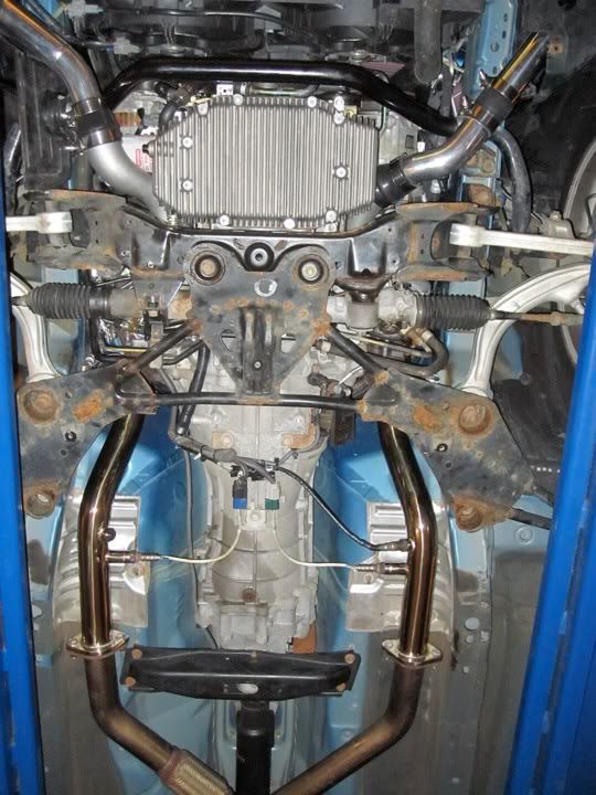
You can see the pipe in this pic. My turbo system is HKS based but I am using JWT intercooler pipes for the most part.
I have a signal coming off the first charge pipe after each turbo. The two signals are then tee'd together and go to the boost control solenoid. The pressure signal for the actual boost controller comes from the intake manifold.
If you are going to drill and tap something I would recommend doing so in a cast piece or something with some substantial thickness. I would not try to drill and tap a thin walled charge pipe, and I would not try to JB weld it in place either.
Actually I think those hose taps you linked to are a handy solution, they should work fine. That said I would still drill and tap a thick section or weld something on if you have the time and the tools.
I think I found the issue to my boost issue.
The port on my wastegate for compressor reference, was litterally loose, it's a bango type bolt, I could spin it with my finger, so there was no way boost reference was getting to the side port, and was only being fed from the top port from the boost controller.
Atleast I hope this is the issue.
Here is how you fix it, or get to that pesky bolt on the wastegate which sits on TOP of the bell housing.


I went and got 10' of new 1/4" fuel line.
Replaced all the vacuum lines from the Boost Controller to the wastegates.
Blood, sweat and beers my friends.

The port on my wastegate for compressor reference, was litterally loose, it's a bango type bolt, I could spin it with my finger, so there was no way boost reference was getting to the side port, and was only being fed from the top port from the boost controller.
Atleast I hope this is the issue.
Here is how you fix it, or get to that pesky bolt on the wastegate which sits on TOP of the bell housing.
I went and got 10' of new 1/4" fuel line.
Replaced all the vacuum lines from the Boost Controller to the wastegates.
Blood, sweat and beers my friends.

Maybe pointless since you found the problem, but you can just put a check valve in-line if you're going off manifold pressure. they're like 10 bucks and will do fine if you're boosing under 15 lbs. They also make some heavy duty ones if you go above that. Good luck!

Thread
Thread Starter
Forum
Replies
Last Post