How many hours approx. to install headers?
#23
REMOVAL
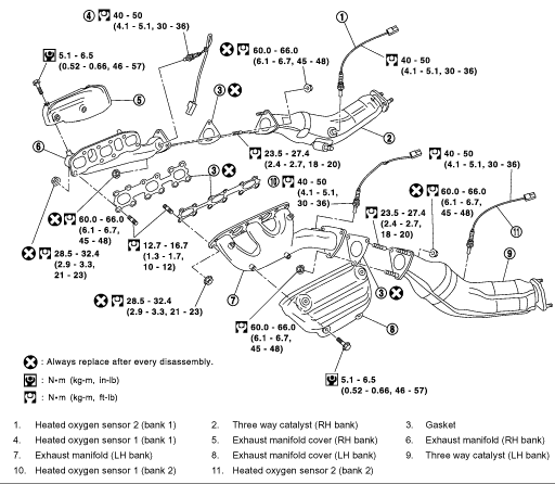
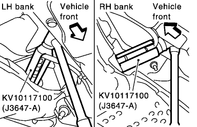
Remove strut tower bar.
Remove engine cover with power tool. See: Engine\Intake Manifold\Service and Repair
Remove air cleaner case and air duct.
Remove undercover with power tool.
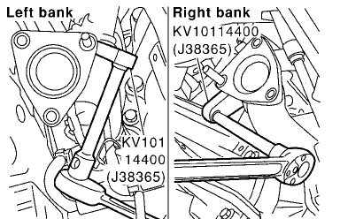
Using heated oxygen sensor wrench (special service tool), remove rear heated oxygen sensors.
CAUTION: Be careful not to damage heated oxygen sensor.
Remove bracket between right/left catalytic converter and transmission.
Remove three way catalyst.
Using heated oxygen sensor wrench (special service tool), remove front heated oxygen sensors.
CAUTION: Be careful not to damage heated oxygen sensor.
Remove water pipes on both RH and LH side.
Remove exhaust manifold cover.
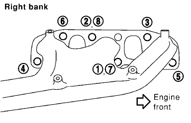
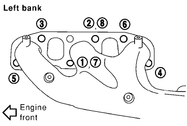
Loosen nuts in the reverse order of illustration to remove exhaust manifold with power tool.
CAUTION: Disregard the numerical order No. 7 and No. 8 in removal.
INSPECTION AFTER REMOVAL
Surface Distortion
Use a reliable straightedge and feeler gauge to check the flatness of exhaust manifold fitting surface.
Limit:..................0.3 mm (0.012 inch)
EXHAUST MANIFOLD AND THREE WAY CATALYST
INSTALLATION
Install in the reverse order of removal paying attention to the following.
Exhaust Manifold Gasket
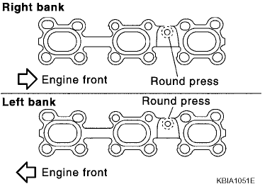
Installation of Exhaust Manifold Gasket
Install in direction shown. (Follow same procedure for both banks.)
Locate thick side of port connecting part on right side from technician's view.
Locate round press in thick side of port connecting part above center level line of port.
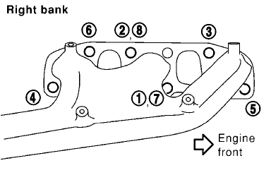

Installation of Exhaust Manifold
If stud bolts were removed, install them and tighten to the torque specified.
12.7 - 16.7 Nm (1.3 - 1.7 kgf-cm, 10 - 12 ft. lbs.)
Install exhaust manifold in the numerical order as shown in the figure.
Tighten nuts No. 1 and No. 2 in two steps. The numerical order No. 7 and No. 8 shows second step.
Installation of Heated Oxygen Sensor
CAUTION: When using heated oxygen sensor wrench (KV10114400), tighten to the middle of specified torque because length of tool may induce slight indication increase. Do not tighten to the maximum spec if fed torque.
Before installing a new heated oxygen sensor, clean exhaust system threads using heated oxygen sensor thread cleaner tool, J-43897-18 or J-43897-12, and apply anti-seize lubricant.
Do not over torque the heated oxygen sensor. Doing so may cause damage to the heated oxygen sensor, resulting in the MIL coming on.
© 2007 ALLDATA LLC. All rights reserved.
Terms of Use

Remove strut tower bar.
Remove engine cover with power tool. See: Engine\Intake Manifold\Service and Repair
Remove air cleaner case and air duct.
Remove undercover with power tool.

Using heated oxygen sensor wrench (special service tool), remove rear heated oxygen sensors.
CAUTION: Be careful not to damage heated oxygen sensor.

Remove bracket between right/left catalytic converter and transmission.
Remove three way catalyst.
Using heated oxygen sensor wrench (special service tool), remove front heated oxygen sensors.
CAUTION: Be careful not to damage heated oxygen sensor.
Remove water pipes on both RH and LH side.
Remove exhaust manifold cover.


Loosen nuts in the reverse order of illustration to remove exhaust manifold with power tool.
CAUTION: Disregard the numerical order No. 7 and No. 8 in removal.
INSPECTION AFTER REMOVAL
Surface Distortion
Use a reliable straightedge and feeler gauge to check the flatness of exhaust manifold fitting surface.
Limit:..................0.3 mm (0.012 inch)
EXHAUST MANIFOLD AND THREE WAY CATALYST
INSTALLATION
Install in the reverse order of removal paying attention to the following.
Exhaust Manifold Gasket

Installation of Exhaust Manifold Gasket
Install in direction shown. (Follow same procedure for both banks.)
Locate thick side of port connecting part on right side from technician's view.
Locate round press in thick side of port connecting part above center level line of port.


Installation of Exhaust Manifold
If stud bolts were removed, install them and tighten to the torque specified.
12.7 - 16.7 Nm (1.3 - 1.7 kgf-cm, 10 - 12 ft. lbs.)
Install exhaust manifold in the numerical order as shown in the figure.
Tighten nuts No. 1 and No. 2 in two steps. The numerical order No. 7 and No. 8 shows second step.
Installation of Heated Oxygen Sensor
CAUTION: When using heated oxygen sensor wrench (KV10114400), tighten to the middle of specified torque because length of tool may induce slight indication increase. Do not tighten to the maximum spec if fed torque.
Before installing a new heated oxygen sensor, clean exhaust system threads using heated oxygen sensor thread cleaner tool, J-43897-18 or J-43897-12, and apply anti-seize lubricant.
Do not over torque the heated oxygen sensor. Doing so may cause damage to the heated oxygen sensor, resulting in the MIL coming on.
© 2007 ALLDATA LLC. All rights reserved.
Terms of Use
Last edited by Fastass350z; 05-25-2007 at 06:54 AM.
Thread
Thread Starter
Forum
Replies
Last Post


