
WAY Overly Complicated Intake


Thread Starter
Registered User
iTrader: (2)
Joined: Sep 2011
Posts: 309
Likes: 2
From: Murfreesboro, TN
Well I did a little more digging trying to find the pop-charger CFM and found this article (http://www.nicoclub.com/archives/kn-vs-oem-filter.html). Kind of indirectly related to what I'm doing, but good information as far as oil (k&n) vs dry vs OE paper filters.
Does anyone have any experience with aFe filters? Since apparently after reading that article, im tempted on changing filters...http://afepower.com/shop/details_new...5L&&brandID=59
Does anyone have any experience with aFe filters? Since apparently after reading that article, im tempted on changing filters...http://afepower.com/shop/details_new...5L&&brandID=59
Thread Starter
Registered User
iTrader: (2)
Joined: Sep 2011
Posts: 309
Likes: 2
From: Murfreesboro, TN
So cut out some larger diameter cardboard pieces. poked holes and used some weedeater strands to mimic where the ring would sit and make sure it was lined up correctly. I made my cutouts in increments of 5mm to make it easier. and it seems like I can only move up to 125mm diameter. Because as pointed out below, if I go to 130mm I will be hitting the bulge in the box. I do not want to cut the ring to over or around that bulge. I am fine with shaving the top, as you can see how fairly flush it sits with the top of the box. I think I might settle on 125mm with shaving the top down, thanks denchan. Going to fine tune the trimming at the top to see if I can get it as flush as possible.


Thread Starter
Registered User
iTrader: (2)
Joined: Sep 2011
Posts: 309
Likes: 2
From: Murfreesboro, TN
Well after this I started a new piece to make it more flush to the box. I realized my top wire was not coming straight through. It was hitting a corner of the box where the stack is tucked in. So it was causing my template to be shifted downward, and I was not maximizing my diameter. With how my I am having to cut off to fit the template flat, I worked it out where my cut when straight my "mounting" hole. Since the contour of the box isn't exactly flat all the way across the top, I think I got about as good as I'm going to get. I'll post the pics once I download them to my comp.
Thread Starter
Registered User
iTrader: (2)
Joined: Sep 2011
Posts: 309
Likes: 2
From: Murfreesboro, TN
Ok, I got my dremel charger and shaved down those two areas. The fitment is way better and almost hellaflush. I think I'm good with this outline unless anyone sees an area of opportunity I'm missing.
Fitment before dremel

With back-lighting to show how flush

Fitment after dremel

Back-lighting to show how hellaflush. Yes it is angled on the left. You can see where the outline touches the box on bottom left? I could dremel that down, but not by a lot. The angle isn't to terrible, and I will only dremel area if I need to.

Now to the outline on the ring. I put a very thin on there only because I wanted to make sure I outlined the cardboard as best as possible with a pen. BLUE line is original starting point. BOLD black was CD outline. THIN black is possibly final outline. Almost a perfect compromise minus the slight chop-off at the top. And I'm not really giving up that much compared to the CD outline.


If you're wondering what niche is, that is where the bolt technically would be. This is very critical since I have to line it up EXACTLY as not to screw up where the ring at the top and not on the bottom.

I got it pretty close, I think.

I'm done for tonight, going to play some black ops 2. PS3 - WALDO___36 (<< that's 3 underscores, because 1 & 2 underscores was already taken)
Thread Starter
Registered User
iTrader: (2)
Joined: Sep 2011
Posts: 309
Likes: 2
From: Murfreesboro, TN
PSYCH!! Thought of this right as I was walking away from my table. I think this shot kind of puts it into perspective how big 125mm is. That is the ring, my template, then the '03 bracket bolted to the ring. And now I'm going to play video games.


Thread Starter
Registered User
iTrader: (2)
Joined: Sep 2011
Posts: 309
Likes: 2
From: Murfreesboro, TN
I did it so I could have a reference point for when I drew the outline on the ring. Since I am cutting part of the ring flat, I need to make sure it's lined up correctly that bolt hole. If I didn't and just laid the template down and drew the outline, I could flattening a section that won't match the contour of the box. For me it just seemed easier to that to make everything a little more precise.
I did it so I could have a reference point for when I drew the outline on the ring. Since I am cutting part of the ring flat, I need to make sure it's lined up correctly that bolt hole. If I didn't and just laid the template down and drew the outline, I could flattening a section that won't match the contour of the box. For me it just seemed easier to that to make everything a little more precise.
Thread Starter
Registered User
iTrader: (2)
Joined: Sep 2011
Posts: 309
Likes: 2
From: Murfreesboro, TN
I got two redesigns done today. 3 fit better than 2, but I sacrificed a little more up top than I wanted to. So I outlined 3 on a new circle and used my dremel to be more precise. This is 4 with the outline from 3.

I know it looks pretty ridiculous, but the better I can fit it up top in that corner the better it sits everywhere. And here is what it looks like on the ring. The very thin green line is 4th design. You can see how close I am to the CD outline (thick black) and how well it sat up near that top corner.


Here is what 4 looks like in the box. It is almost perfectly contoured in that corner and against the rounded edges right there.


Since I was able to tuck the template in so well, I am sitting on top of the '06 stack. If that doesn't get you much indication of flush, this pic might.

Yes, there still is some light coming through but it is still because of the hump on the right. It shouldn't be a factor once the ring is cut, but if it causes an issue it shouldn't take much to dremel it flat and clear.
I think I'm done cutting and measuring. I'm going to call the guy Tues or Wed to see if he'll be able to squeeze me in next week. He told me he would be pretty all next week, so I don't know when I'll be able to get this ring milled. And hopefully he won't charge me too much since I have the outline of where I would like to have it milled.
Thread Starter
Registered User
iTrader: (2)
Joined: Sep 2011
Posts: 309
Likes: 2
From: Murfreesboro, TN
It is thicker yes, but I need to have the ring as close to the height of the current stack. So the better I can contour the box, the more I can get it closer to the exact height I need. I should be good with this 4th design, but I still might need the guy to go back and shave around the top on the under side. That way it would be thinner at the top, if you get what I mean.
Thread Starter
Registered User
iTrader: (2)
Joined: Sep 2011
Posts: 309
Likes: 2
From: Murfreesboro, TN
So just tinkering around, I put the pop charger back on and have been running it for about a week. The computer went CRAZY once I got onto the interstate and put into cruise control. I didn't gas it real hard or anything to get up to speed. But once I got it at cruise on 75, I clicked it over to watch my Distance To Empty miles....it went from 242 getting on the interstate to 205 after about five miles! It worked its way back up by the time I got to Nashville to around 237 which also seemed weird. For the first few days, that's how it went with the computer adjusting to what I assume would be additional air flowing in. A couple of times flooring it getting on the interstate, it seems to hiccup right as the powerband starts around 3700-3900. Tried to get vid of it yesterday, but too much traffic by the on ramp.
Also, to go along with "heat soak" theories, I think I have figured something out. For any Z driver running factory headers, I think the pop charger would be great and not suffer "heat soak" too badly if at all. The factory headers have heat shields that reduces engine bay temps by a lot. However, anyone running aftermarket headers totally opens the pop charger to a ton of heat. I didn't realize how close the headers were to the intake until I swapped back the PC. I understand that once the car starts moving the temps are reduced drastically, but those headers are just so close. This is another reason why I think the factory box is better because is blocking all that heat right behind it when using aftermarket headers.


Also, to go along with "heat soak" theories, I think I have figured something out. For any Z driver running factory headers, I think the pop charger would be great and not suffer "heat soak" too badly if at all. The factory headers have heat shields that reduces engine bay temps by a lot. However, anyone running aftermarket headers totally opens the pop charger to a ton of heat. I didn't realize how close the headers were to the intake until I swapped back the PC. I understand that once the car starts moving the temps are reduced drastically, but those headers are just so close. This is another reason why I think the factory box is better because is blocking all that heat right behind it when using aftermarket headers.


Thread Starter
Registered User
iTrader: (2)
Joined: Sep 2011
Posts: 309
Likes: 2
From: Murfreesboro, TN
Really? There's a lot of heat coming off those headers. And without heat shields or heat wrap it just seems like all of heat would fill every crevasse of that bay. I even noticed once these headers were installed, the carpet on the inside gets warm on the trans channel.
Air pushes the heat out when moving. Heat to the plastic tube above the headers doesn't hurt much, the air is only in the tube for a split second , and the tube will also cool down quickly once the car is moving.

waldo36 is probably seeing maf sensor turbulence with the cone filter. I've been reading about this sort of thing for 20 years, dating back to Z32's.
Also, I just put a 3.5" BPI stack into a stock airbox this weekend in a similar manner. Your redesign #2 looks closest to what I have. It's flat on one side, and if you view it with the flat side down, the upper left and right areas are trimmed heavily. Mine has the 3.5" tube extending out the back of the box. I'll fab a 3.5" intake tube with mafs adapter soon.
Also, I just put a 3.5" BPI stack into a stock airbox this weekend in a similar manner. Your redesign #2 looks closest to what I have. It's flat on one side, and if you view it with the flat side down, the upper left and right areas are trimmed heavily. Mine has the 3.5" tube extending out the back of the box. I'll fab a 3.5" intake tube with mafs adapter soon.
Thread Starter
Registered User
iTrader: (2)
Joined: Sep 2011
Posts: 309
Likes: 2
From: Murfreesboro, TN
Well got the ring milled today. Had to do a lot more cutting once we tried fitting it in the box. From my final design, we basically did have to go back to design 2 with one modification. I'll post pictures tomorrow comparing '06 ring and my new ring.
Thread Starter
Registered User
iTrader: (2)
Joined: Sep 2011
Posts: 309
Likes: 2
From: Murfreesboro, TN
Alrighty then, finally had some time to go get the ring milled and she looks fantastical! And when my shop guy was cutting, I quickly realized my cardboard cut out was far from accurate....It was close, but there were about 5 extra recuts on the mill and band saw to get fitment correct. Enough talking, here's the pics.
First I set the '06 ring on top of it, just to see how much bigger it was the the entire ring/bracket assembly.


Then I drew an outline of the '06 ring max diameter on for a true comparison of how much more surface area there is.

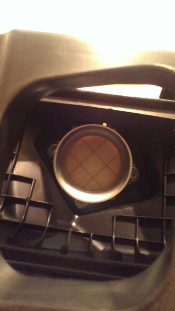
And the main goal of this project, perfect transition from box to MAF housing!

It's BIG

And two pics to show the true comparison of the '06 ring vs my new ring.

First I set the '06 ring on top of it, just to see how much bigger it was the the entire ring/bracket assembly.


Then I drew an outline of the '06 ring max diameter on for a true comparison of how much more surface area there is.

And the main goal of this project, perfect transition from box to MAF housing!

It's BIG

And two pics to show the true comparison of the '06 ring vs my new ring.

