
DIY total N/A backyard build


the dyno was a dyno jet, and i have one sheet when i ripped 278 whp, but i cant find the my last run that ripped 285, the only difference that was made from the extra 7 whp i gained was my guy who installed simply poured some water on my plenum bc it was so hot inside the shop and i jumped from 278 to 285 that quick, and right before he did my last run he even told me that i was closer to the 280 whp mark

Thread Starter
Registered User
iTrader: (46)
Joined: Jan 2004
Posts: 491
Likes: 2
From: Toms River, NJ
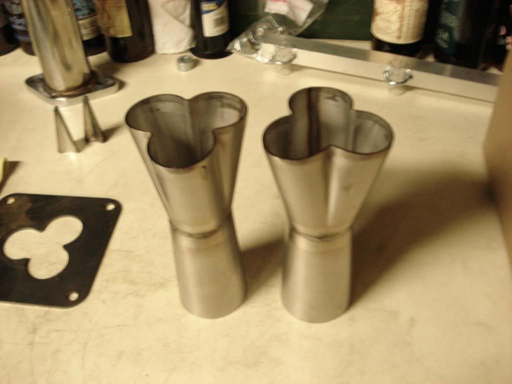
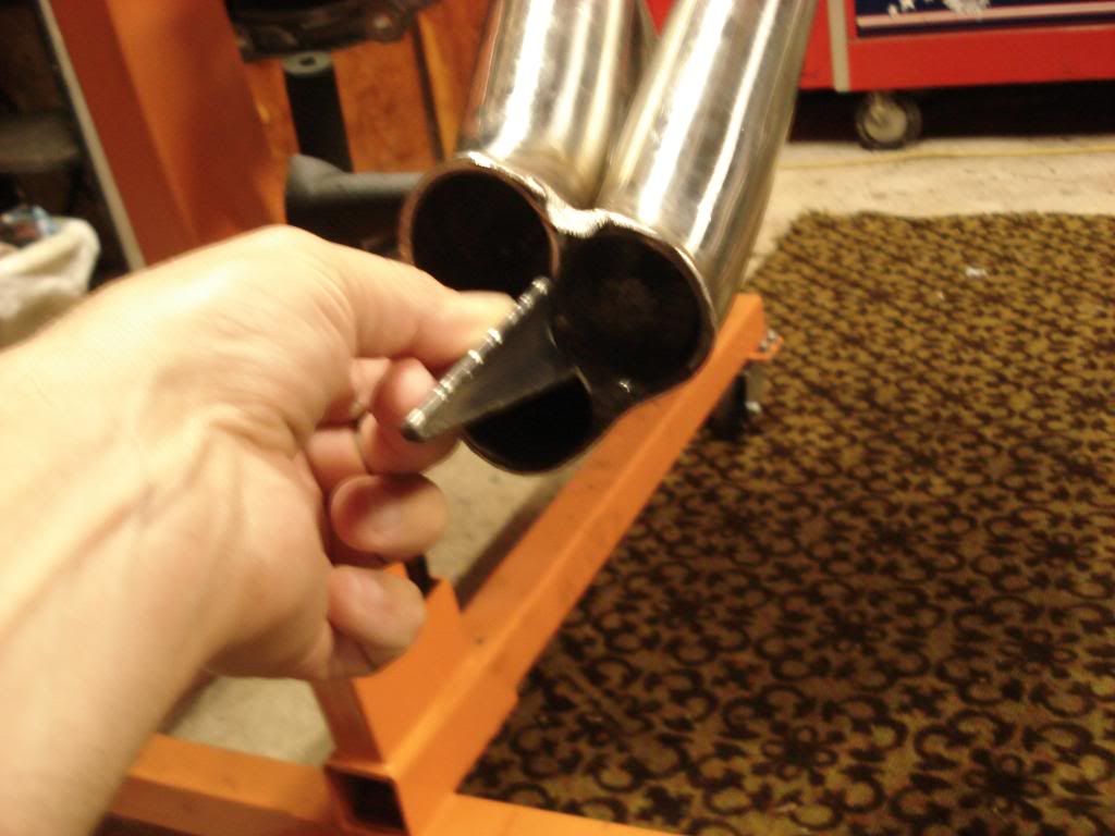
The collectors came in monday, handed them over to the welder yesterday. Turns out I have enough room to run them uncut, so the collector outlet will be 2" and the 7 degree transition cone will go back out to 2.5". The guy at megs told me that combination would outflow cutting them or straight collectors.
http://www.carcraft.com/techarticles...rbs/index.html
Anyway with this style collector I am using the collector outlet should be about 20% larger than the primary so 1.625x.2=.325 and 1.625+.325=1.95
So 2" is just right for a 1 5/8" primary. Now if I went 1.75" primary I would need to cut it back to open it up to 1.75x.2=.35 so 1.75+.35=2.1
If anyone has different information than this please share. Reality is you make a whole bunch of header combinations and dyno test them all but I have a sub 1k budget so its what I am doing; cross your fingers, say a prayer, and hope they work. Amount invested so far 366(headers) and 155(collector kit) so $521 now going to see how much welding is and I am still on the fence about ceramic coating them because this engine is so sensitive to IAT's. Need to address a cold air intake or at least seal in the popcharger with a box of some sort.

I have one for sale.

I dont understand why you would NOT coat them if your concerned with intake temps. Coating them would help with underhood temps and keep the heat in teh exhaust. A good thing.
Thread Starter
Registered User
iTrader: (46)
Joined: Jan 2004
Posts: 491
Likes: 2
From: Toms River, NJ
They will probably end up coated because if I couldn't leave those collectors...Stillen intake is the same as the popcharger with a "better" heat shield, I need to get ambient air to the filter better and keep all the engine bay air/heat away. Anybody know what the flow potential of the stock size filter in a k&N or aem? I am thinking some brake ducting hose, venturi in the stock air box, and a dryer duct fixture from home depot screwed in behind the bumper support.
Last edited by 1cockyZ; Aug 5, 2009 at 08:28 AM.
Cocky dont worry about that. I spoke with adam from z1 a while back and he said so much air gets up there that no ducting, or vents in that location would give you any benefit.
I was going to do the exact same thing on both sides as you said(HR) And was going to use some thermocouples to see if I got any difference. Adam told me he tryed it a few years back and saw no recognizable difference.
I was going to do the exact same thing on both sides as you said(HR) And was going to use some thermocouples to see if I got any difference. Adam told me he tryed it a few years back and saw no recognizable difference.
In my experience, this is where a good cold air has benefits - it keeps the IAT's more stable, and able to recover quicker vs a short ram. Once the car is moving however, I found minute differences between the OEM airbox and my cold air (Gruppe M) in terms of peak IAT's. If the car was left sitting for awhile idling, which builds heat up quickly (I posted my findings about a year ago...I forget what the temps were now and I've since deleted the log files) the Gruppe-M was able to recover about 2 x quicker as I recall. The Gruppe-M uses a similar setup to what 1cocky is saying - a bumper mounted duct with a flexible hose to the carbon airbox, which houses a massive conical filter. I don't have an OEM bumper though, so not sure how much that affects things. I never tried ducting air to the OEM airbox. As jiggy mentioned, there is alot of airflow through the engine bay, even with a stock hood. With a vented hood, I suspect peak temps are even better (I'll know soon as I put my vented hood back on)
I'm just doing a normal short ram this time around on mine, at least to start with. I'm less worried about the massive heat soak issues vs my previous setup since I'll be coating everything before putting it back together. Given that my car never gets drag raced, I am not concerned at all with it just sitting idling. If the short ram proves to be a limitation, we'll simply extend the pipe and make it a cold air
I'm just doing a normal short ram this time around on mine, at least to start with. I'm less worried about the massive heat soak issues vs my previous setup since I'll be coating everything before putting it back together. Given that my car never gets drag raced, I am not concerned at all with it just sitting idling. If the short ram proves to be a limitation, we'll simply extend the pipe and make it a cold air
Thread Starter
Registered User
iTrader: (46)
Joined: Jan 2004
Posts: 491
Likes: 2
From: Toms River, NJ
I can't find my stock air box but I want to chop it up enough to put the popcharger in it. I can make a new top for it to cover it up. The bolt spacing on the popcharger venturi ring is the same as stock so the holes in the box are there so everything will line up just have to cut the whole bigger. I have noticed 1.5mph drop off on back to back runs so iat's and coolant temps play hell with these cars.
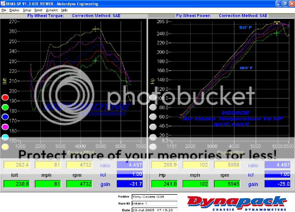
Heat soak on the usual short ram and cold air intakes can reduce launching power considerably.
When stopped at a stop light or staging area air intake temperatures rise rapidly from ambient to 120'-150' F.
At launch, it takes about 6-8 seconds for the MAF sensor to register ambient temperatures at a WOT launch... but as you can see in the plot below, that can be 6-8 at a significant loss of power.
Thread Starter
Registered User
iTrader: (46)
Joined: Jan 2004
Posts: 491
Likes: 2
From: Toms River, NJ
That is about what I expected the car feels very "soft" through the 1/8 mile but from the 1/8 to 1/4 I have a consistent 23.xx mph gain. I know on the dyno Vince lets the coolant temps get down to 172-173 to insure consistency. Maybe the nismo thermostat would help just a lot of money for what should be a $20 part.
The Nismo thermostat won't really help in that regard.
It opens at a lower temperature than the stock thermostat but both are fully open at the operational temperatures, so it doesn't do anything to increase the heat transfer rate.
I would skip that one and save some $$$.
A bigger and better radiator will definitely help though.
It opens at a lower temperature than the stock thermostat but both are fully open at the operational temperatures, so it doesn't do anything to increase the heat transfer rate.
I would skip that one and save some $$$.
A bigger and better radiator will definitely help though.

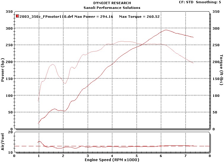
I'm pretty certain the major reason the curve peaks so early on the DE motor is due to the intake runners being too narrow, especially around the curves. I would have to dig up the notes but I did some calculations when I had a Z a few years ago (and will pick one up again eventually...). According to what I have learned from reading SAE articles the flow through runners starts to choke when it reaches speeds of about 0.6 mach (local relative mach). The stock Z reaches that around 6200rpms, which is where it peaks with everyone that has stock runners. Even when everything else is mostly proper:
(rednezz Z)
I notice that Z1's car had a machinist work over the intake manifold (and is working over his new cosworth manifold to match it), that the cosworth engine (of top shop challenge fame) had a ported lower manifold on it's list of mods, and that ivory gt's car also bypasses that problem all together. In fact if you look at his comparison dynos of stock IM vs ITBS, sure the ITB's make power across the whole powerband, but you can see a point where the stock IM's runners are reaching choked flow and the itb's continue to climb:

(IvoryGT Z)
The HR intake manifold addressed the things that were the matter with what nissan attempted in the revup manifold, they maxed out the cross sectional area of the runners (in which geometry necessitated square runners), and the geometry/flowrate problem of the single TB design they had before.
Although longtubes will make an absolute difference in power, they are not going to reshape the curve to continue to climb. Look at SG's car, it makes much more power, but the shape of the curve looks exactly the same.
(rednezz Z)
I notice that Z1's car had a machinist work over the intake manifold (and is working over his new cosworth manifold to match it), that the cosworth engine (of top shop challenge fame) had a ported lower manifold on it's list of mods, and that ivory gt's car also bypasses that problem all together. In fact if you look at his comparison dynos of stock IM vs ITBS, sure the ITB's make power across the whole powerband, but you can see a point where the stock IM's runners are reaching choked flow and the itb's continue to climb:
(IvoryGT Z)
The HR intake manifold addressed the things that were the matter with what nissan attempted in the revup manifold, they maxed out the cross sectional area of the runners (in which geometry necessitated square runners), and the geometry/flowrate problem of the single TB design they had before.
Although longtubes will make an absolute difference in power, they are not going to reshape the curve to continue to climb. Look at SG's car, it makes much more power, but the shape of the curve looks exactly the same.
Thread Starter
Registered User
iTrader: (46)
Joined: Jan 2004
Posts: 491
Likes: 2
From: Toms River, NJ
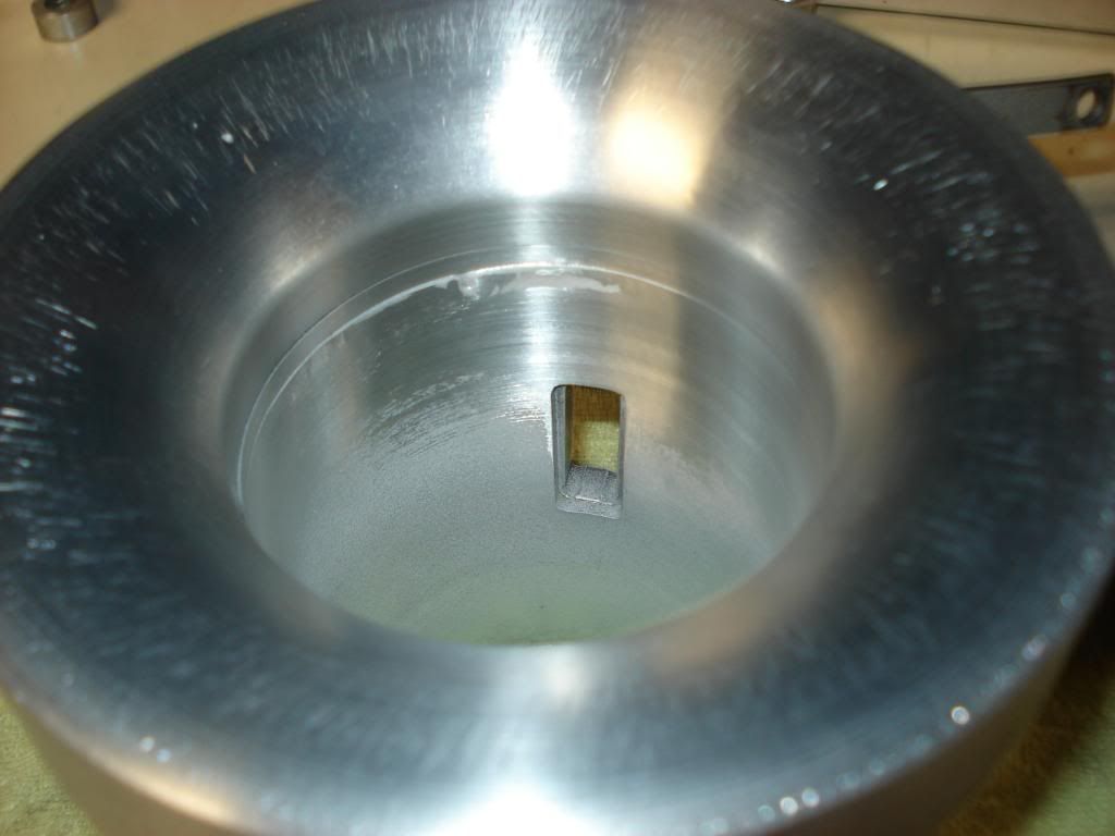
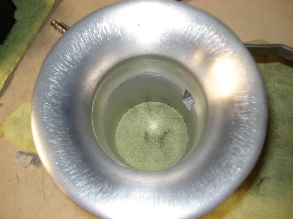
I did this over a year ago but didn't put it on the car when I did the build. Going to match this to the nonrevup lower on the car and add my 72mm tb. I am bored the welder is taking to long with the collectors for my header project. So some more intake mods and a dyno to follow. My z1 big maf is at the machinist getting the popcharger venturi matched perfect as compared to my ^*^*%&%& job I did on it. Enjoy the pics start the dyno predictions.
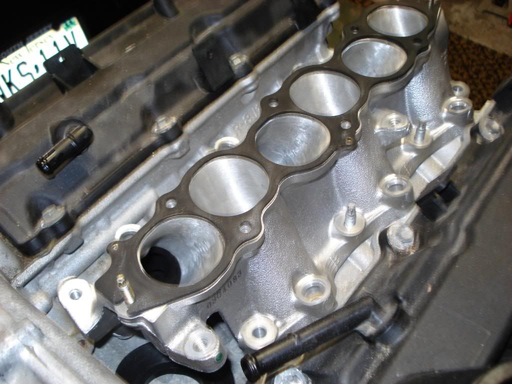
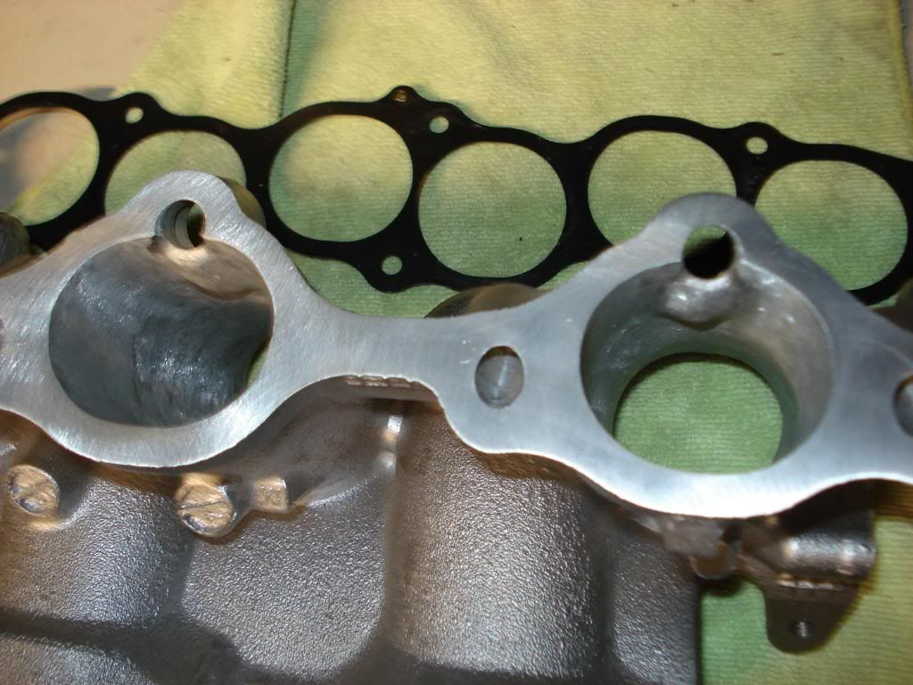
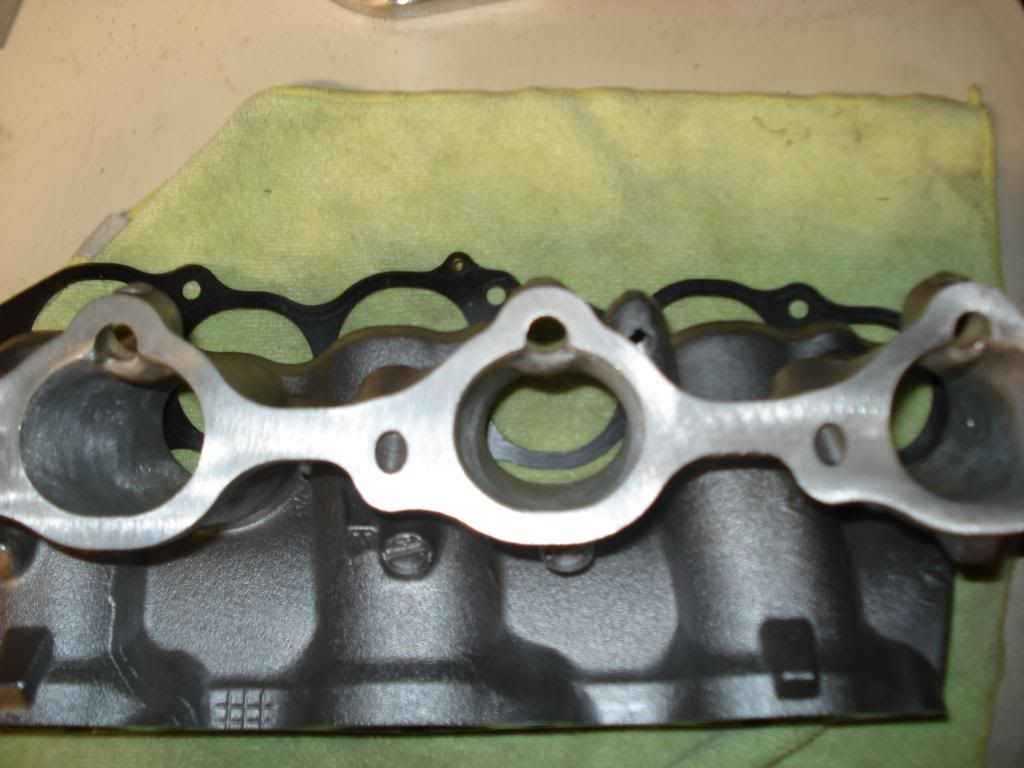
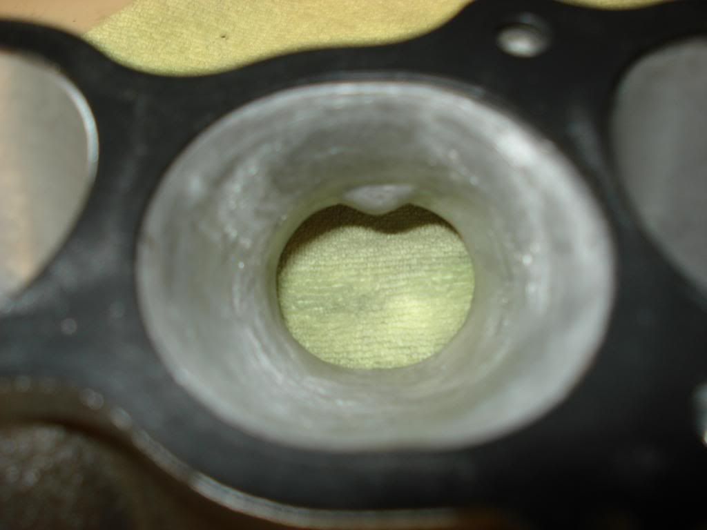
This took me the better part of 4 hours. For anyone who hasn't taken this all apart where the lower meets the cylinder head port there is some nastiness almost looks as bad as the cut marks above the valve seats in the cylinder head ports, if you look at the pics of my valve job where it looks like port work all they did was elimate the factory mistake.
This took me the better part of 4 hours. For anyone who hasn't taken this all apart where the lower meets the cylinder head port there is some nastiness almost looks as bad as the cut marks above the valve seats in the cylinder head ports, if you look at the pics of my valve job where it looks like port work all they did was elimate the factory mistake.

nice work! I got a spare set of TB/intake upper/lower/runners that I was going to port match and clean up. Can't wait to see what kinda gains you get.
thanks for all the great work and keeping us updated. awesome project.
thanks for all the great work and keeping us updated. awesome project.
 [/IMG][/IMG]
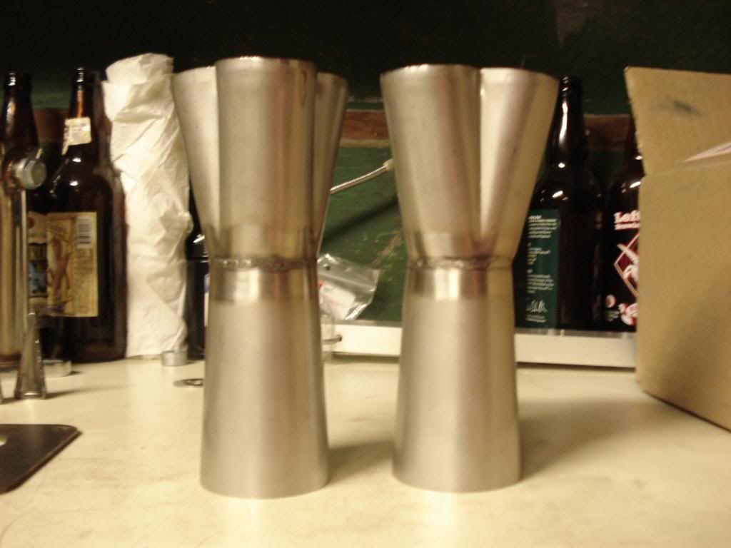

If you don't mind can you pm what it cost to get the venturi lathed. Thanks. What is the time schedule as far as the headers......should be interesting to see the results (and finished product).

Thread Starter
Registered User
iTrader: (46)
Joined: Jan 2004
Posts: 491
Likes: 2
From: Toms River, NJ
Gabe its not welded just machined as 1 piece. The collectors are 16 gauge 304 stainless. If you want to be quick and dirty with matching the popcharger ring to the maf housing a 3 3/16" hole saw from the maf side out with the maf bolted on will be so close.
wow... so you are defiantly stealing all my ideas... haha this is exactly what I planned on doing so please let me know how it goes. There is only one thing left that I plan on doing that you haven't yet.