Rapid Prototyping Race Car Parts
 06-25-2013, 09:19 PM
#1
Registered User
Thread Starter

Join Date: Jan 2010
Location: Minneapolis, MN
Posts: 14
Likes: 0
Received 0 Likes
on
0 Posts
Hey Guys,
I'm an Automotive and Aerospace Applications engineer at Stratasys, a company that makes 3D printers (Before you ask, yes the same machines that are being used to make 3D printed guns, and no they do not impress me! ) My job is to go work with automotive companies like Ferrari, Lamborghini, and race teams and aerospace companies like Boeing and Airbus to advise them on how to 3D print parts that go on their cars/airplanes, or how to use our 3D printing machines to make composites tools, jigs, fixtures, drill guides etc.
Last week I had some time to use my 350z as a test bed for some potential automotive applications and I thought you guys would be interested......
Lets start with the battery. I got a Braile 11lb and needed a good way to mount it. Yay custom battery hold down!
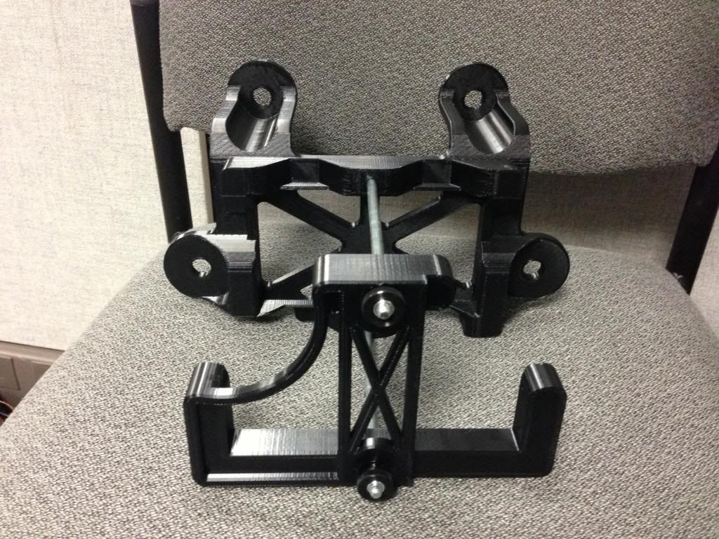
Here is what it looks like fresh out of the machine.
Bolts and thumb screws installed
Tray installed in car (I should probably clean out the leaves in there)
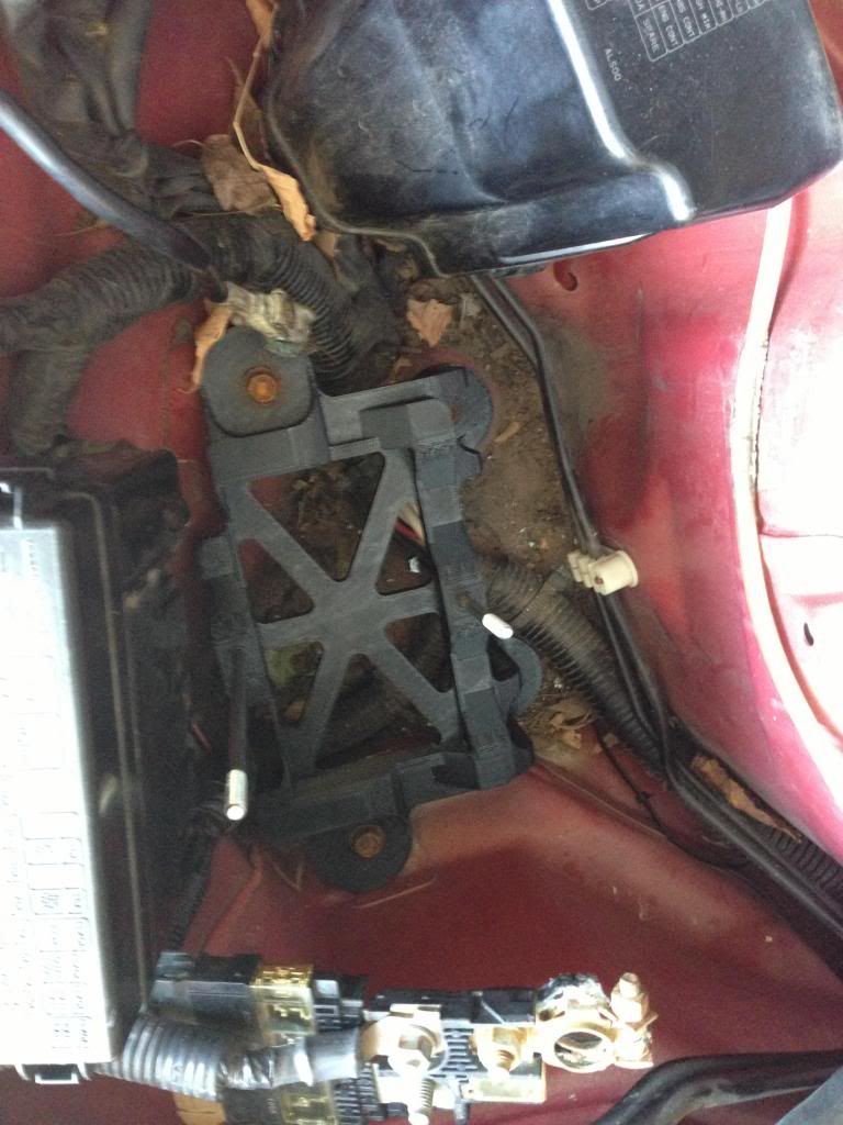
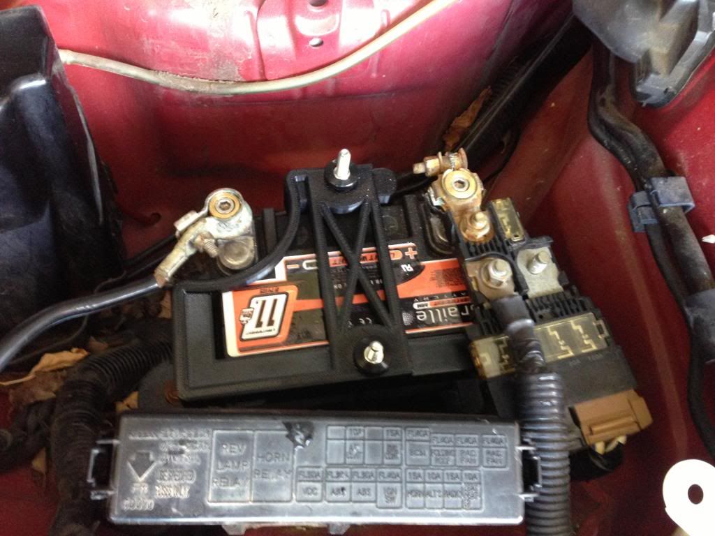
Tray and battery installed. Quite a bit of weight savings with the 11lb battery. Definitely not a good solution for a daily driver though!
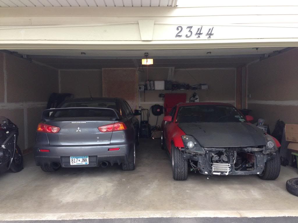
Random Pic of the Toys! Die hard Nissan guys don't hate on the Mitsubishi..... I moved up to Minnesota for this job so I needed something 4wd that could get me around in all the snow and still be fun.
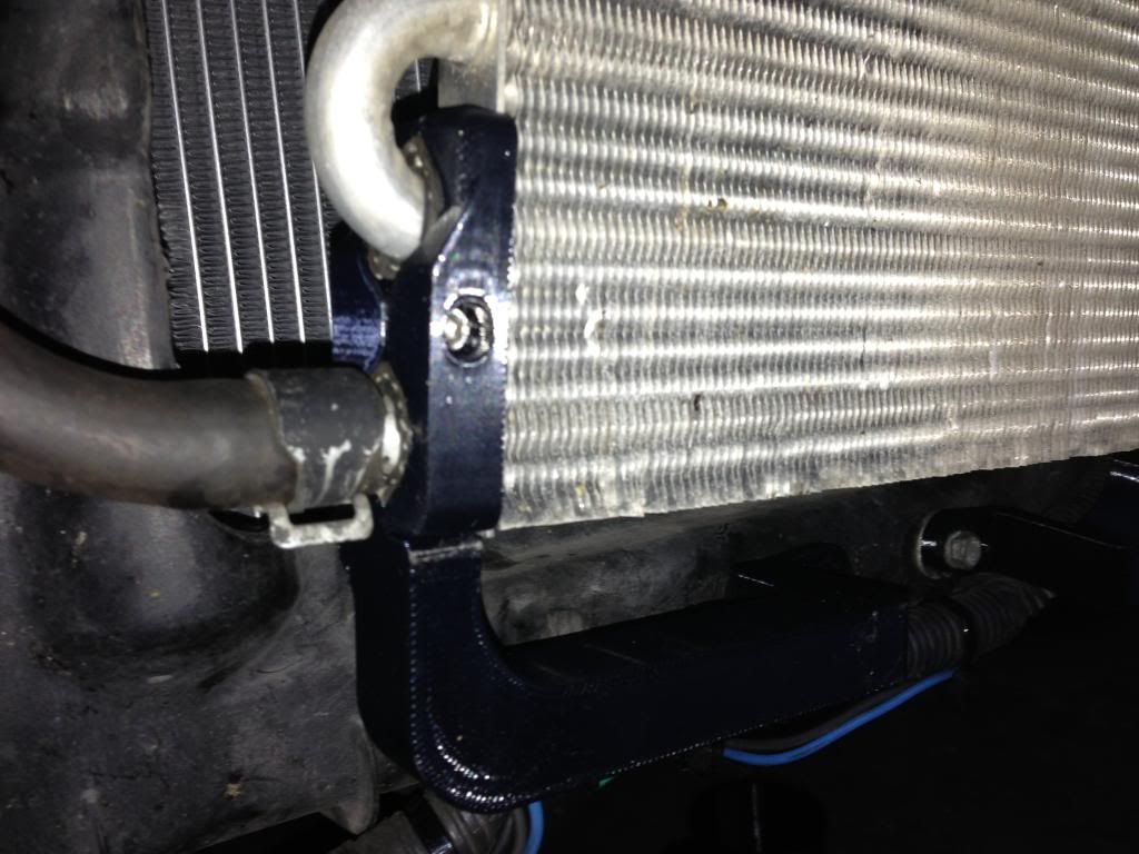
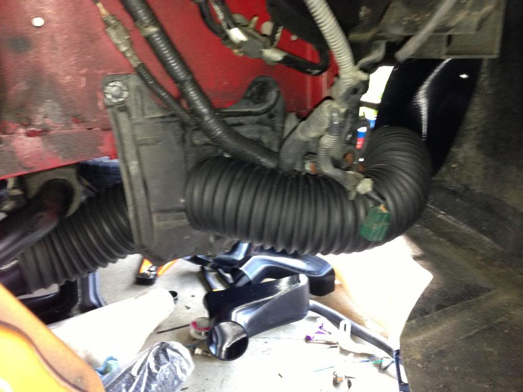
Next is the P/S cooler mount.... Simple enough
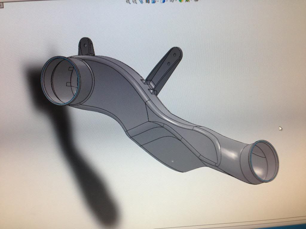
Here is where some tricky design and trial and error came in. I hate just shoving brake ducting behind the strut, so I decided to make an elbow.
Initial CAD model on the computer.
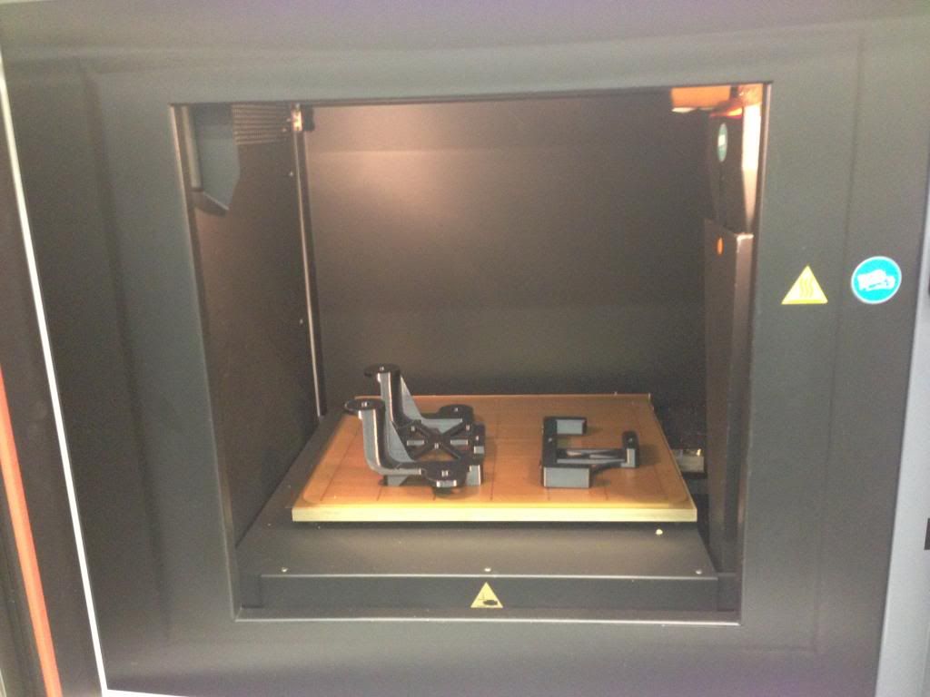
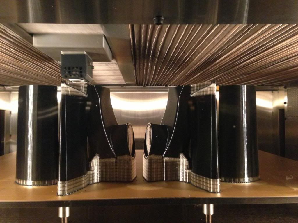
Printing the first try. All of the other columns and clear colored material is to support overhangs. The FDM(Fused Deposition Modeling) printer works like a highly sophisticated and accurate hot glue gun except instead of glue it uses thermoplastics including ABS, Polycarbonate, or in this case ULTEM (High temperature and strength material). The plastic is heated to glass transition temperature (where it gets workable but not quite liquid)and is pushed through a tiny hot glue gun like nozzle. The nozzle deposits the plastic layer by layer to make the part. Each layer is between 0.005" and 0.013" thick, with a trade off of speed vs resolution for the different layer thicknesses.
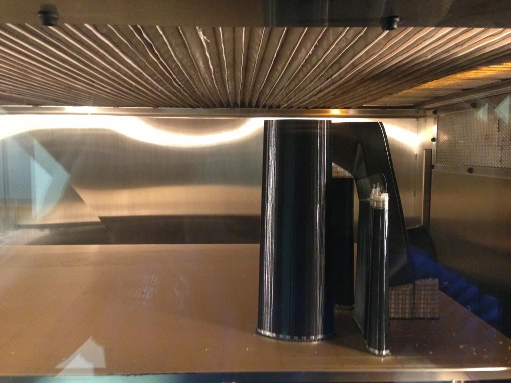
When the nozzle gets to a layer with an overhang, it can't "squirt" the plastic into thin air and expect it to stay where its supposed to. Therefore a secondary support material has to be built up along side the main material so that when it gets to the point with the overhang there is a base to deposit the material onto.
First try duct out of the machine
Revised duct in the machine. I needed more swaybar clearance than I gave in the first version. Luckily with 3D printing you have the option of printing a new design immediately and have it next day! With other manufacturing process such as injection molding/carbon fiber etc... you would be out thousands to tens of thousands of dollars for new tools and it would take weeks or months to get them!
This time I was confident, so I printed the left and the right
New ducts out of the machine. Support material still on.
Next I needed an Inlet for the ducts. I have a N2 bumper so I just used the outermost radiator opening for the inlet.
Here they are directly out of the machine with the support material still attached. For the Ultem material, you have to mechanically break away the support material from the part. Sometimes it is really easy, other times it sticks like crazy or is in hard to reach places. The support material for ABS and PC can be dissolved away in a water/detergent solution.
Installed in the bumper.
It turns out that I needed a 45degree angle on it to clear the radiator support. Onto version 2! I know, I know, measure twice cut once. But cutting twice is so easy!
View from the rear with the tube installed
Finally, I need the outlet of the brake duct to the rotor. For this I used the highest temperature material we have called PPSF. It stands for Poly phenol something cellphone????... I forget . I should look that up... since its kind of my job to know.
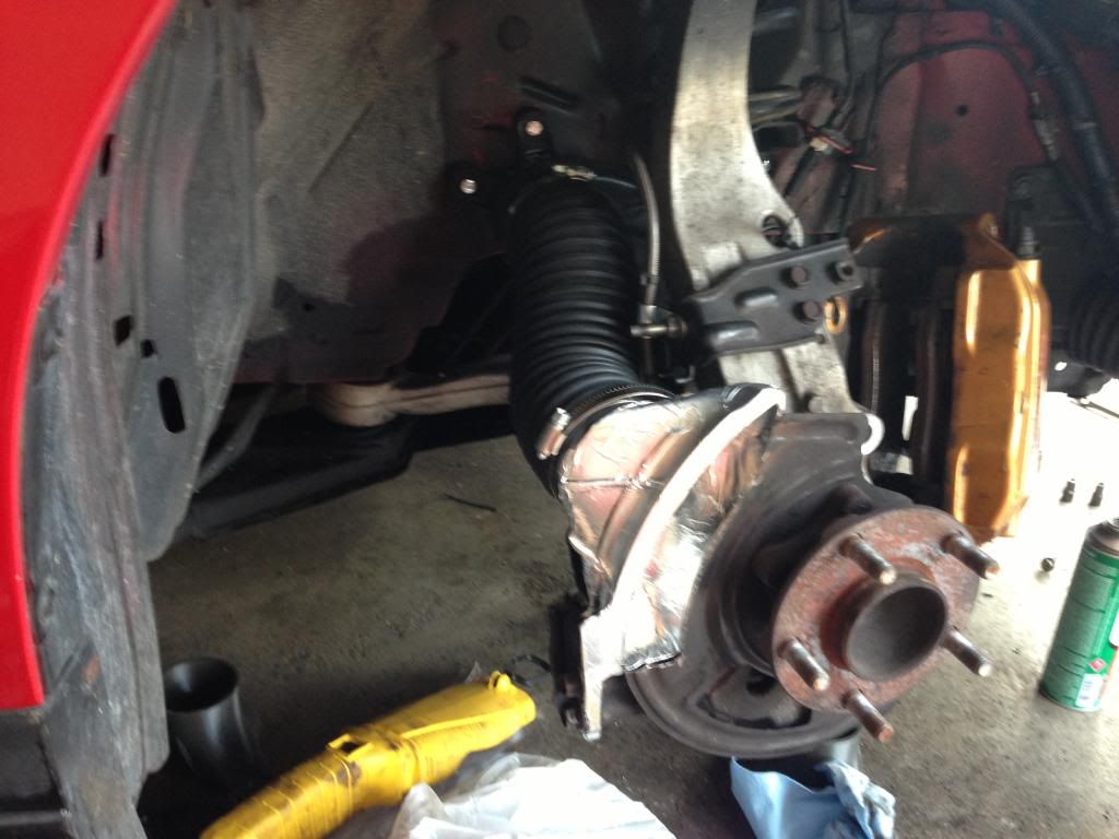
Installed on the car with the elbow duct.
After testing I had to make a version 2 that was shorter to give more room for the hose to contract and stretch while turning the wheel left and right. The PPSF will start to get soft at a little over 400 degrees F. I'm not worried about it melting while on the track, but I'm worried about what happens when I pull off into the paddock with toasty brakes and park it. My solution was to coat it with ceramic engine block paint and cover all of the surfaces facing the rotor with aluminum tape to try and reflect all the radiation coming from the hot rotors.
Haven't had them on the track yet but after bedding in the brakes and letting them sit there are absolutely no signs of heat distortion what so ever!
I'm an Automotive and Aerospace Applications engineer at Stratasys, a company that makes 3D printers (Before you ask, yes the same machines that are being used to make 3D printed guns, and no they do not impress me!
) My job is to go work with automotive companies like Ferrari, Lamborghini, and race teams and aerospace companies like Boeing and Airbus to advise them on how to 3D print parts that go on their cars/airplanes, or how to use our 3D printing machines to make composites tools, jigs, fixtures, drill guides etc.Last week I had some time to use my 350z as a test bed for some potential automotive applications and I thought you guys would be interested......
Lets start with the battery. I got a Braile 11lb and needed a good way to mount it. Yay custom battery hold down!
Here is what it looks like fresh out of the machine.
Bolts and thumb screws installed
Tray installed in car (I should probably clean out the leaves in there)
Tray and battery installed. Quite a bit of weight savings with the 11lb battery. Definitely not a good solution for a daily driver though!
Random Pic of the Toys! Die hard Nissan guys don't hate on the Mitsubishi..... I moved up to Minnesota for this job so I needed something 4wd that could get me around in all the snow and still be fun.
Next is the P/S cooler mount.... Simple enough
Here is where some tricky design and trial and error came in. I hate just shoving brake ducting behind the strut, so I decided to make an elbow.
Initial CAD model on the computer.
Printing the first try. All of the other columns and clear colored material is to support overhangs. The FDM(Fused Deposition Modeling) printer works like a highly sophisticated and accurate hot glue gun except instead of glue it uses thermoplastics including ABS, Polycarbonate, or in this case ULTEM (High temperature and strength material). The plastic is heated to glass transition temperature (where it gets workable but not quite liquid)and is pushed through a tiny hot glue gun like nozzle. The nozzle deposits the plastic layer by layer to make the part. Each layer is between 0.005" and 0.013" thick, with a trade off of speed vs resolution for the different layer thicknesses.
When the nozzle gets to a layer with an overhang, it can't "squirt" the plastic into thin air and expect it to stay where its supposed to. Therefore a secondary support material has to be built up along side the main material so that when it gets to the point with the overhang there is a base to deposit the material onto.
First try duct out of the machine
Revised duct in the machine. I needed more swaybar clearance than I gave in the first version. Luckily with 3D printing you have the option of printing a new design immediately and have it next day! With other manufacturing process such as injection molding/carbon fiber etc... you would be out thousands to tens of thousands of dollars for new tools and it would take weeks or months to get them!
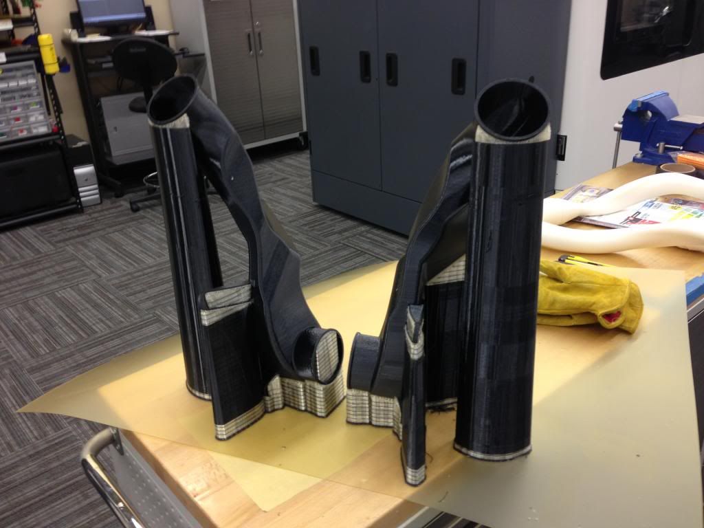
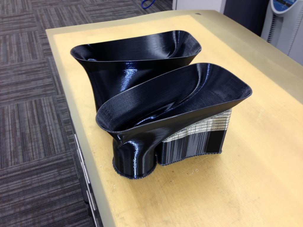
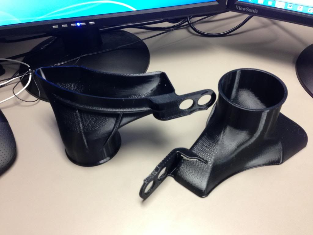
This time I was confident, so I printed the left and the right
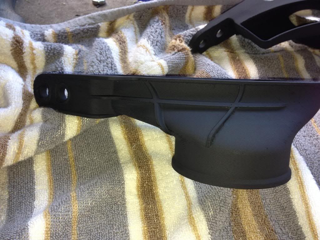
New ducts out of the machine. Support material still on.
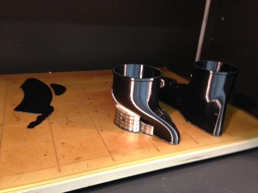
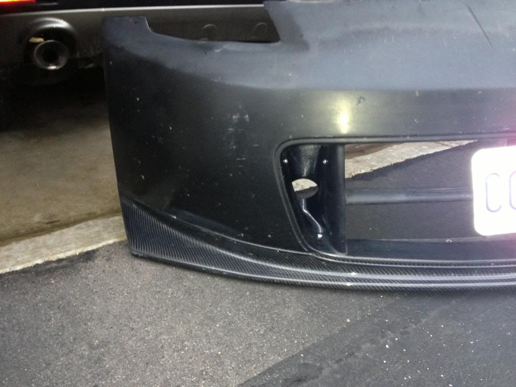
Next I needed an Inlet for the ducts. I have a N2 bumper so I just used the outermost radiator opening for the inlet.
Here they are directly out of the machine with the support material still attached. For the Ultem material, you have to mechanically break away the support material from the part. Sometimes it is really easy, other times it sticks like crazy or is in hard to reach places. The support material for ABS and PC can be dissolved away in a water/detergent solution.
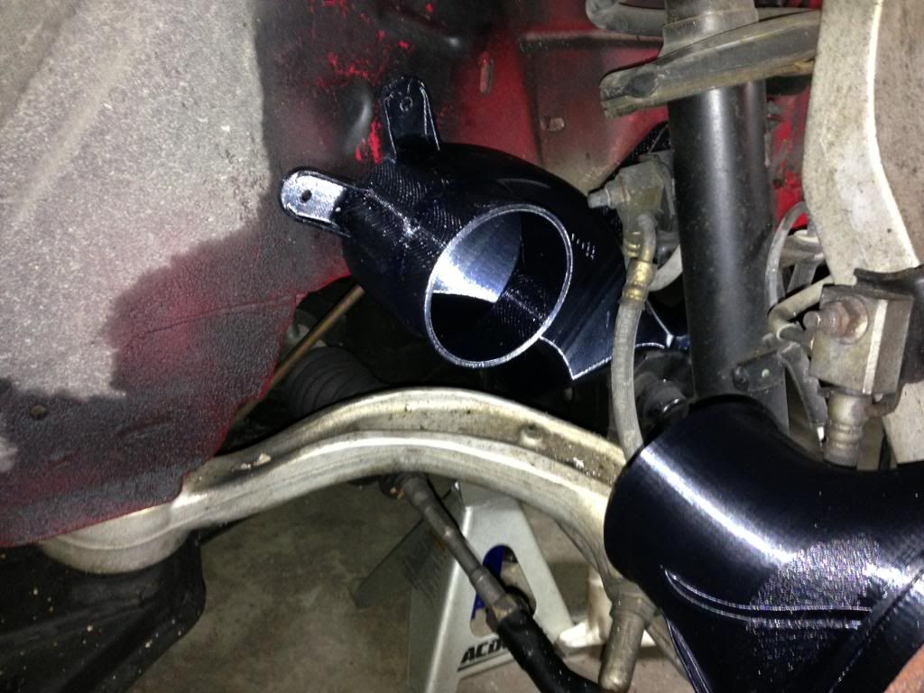
Installed in the bumper.
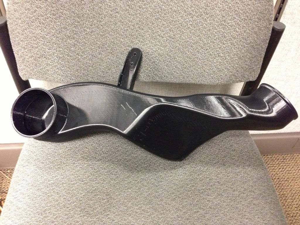
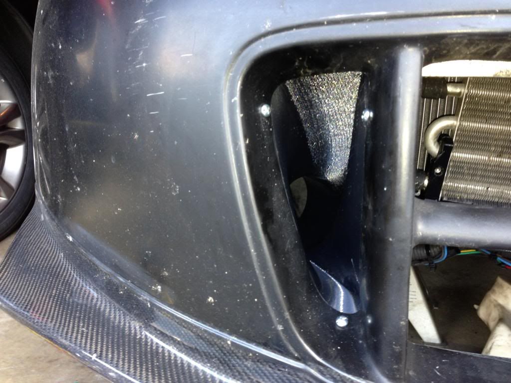
It turns out that I needed a 45degree angle on it to clear the radiator support. Onto version 2! I know, I know, measure twice cut once. But cutting twice is so easy!
View from the rear with the tube installed
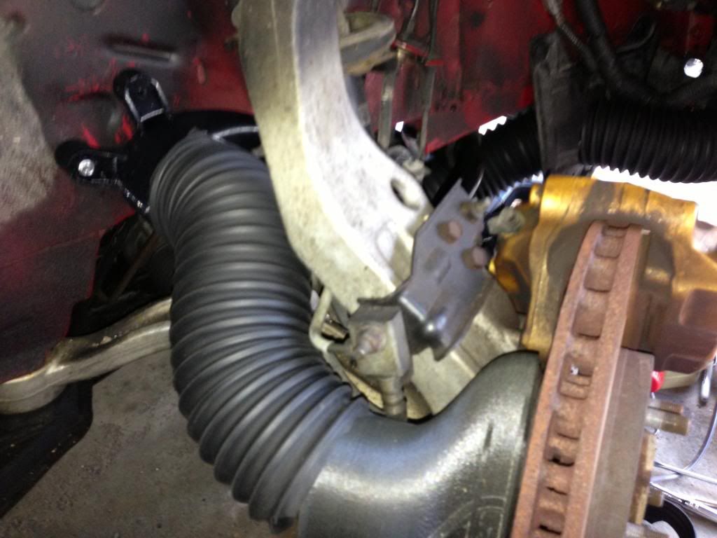
Finally, I need the outlet of the brake duct to the rotor. For this I used the highest temperature material we have called PPSF. It stands for Poly phenol something cellphone????... I forget
. I should look that up... since its kind of my job to know.Installed on the car with the elbow duct.
After testing I had to make a version 2 that was shorter to give more room for the hose to contract and stretch while turning the wheel left and right. The PPSF will start to get soft at a little over 400 degrees F. I'm not worried about it melting while on the track, but I'm worried about what happens when I pull off into the paddock with toasty brakes and park it. My solution was to coat it with ceramic engine block paint and cover all of the surfaces facing the rotor with aluminum tape to try and reflect all the radiation coming from the hot rotors.
Haven't had them on the track yet but after bedding in the brakes and letting them sit there are absolutely no signs of heat distortion what so ever!
 06-25-2013, 09:57 PM
#2
Super Moderator
MY350Z.COM
MY350Z.COM


iTrader: (8)
Holy crap I need a set of those ducts


Trending Topics
06-26-2013, 01:37 PM
#8
New Member
iTrader: (3)

Join Date: May 2011
Location: Indiana
Posts: 190
Likes: 0
Received 0 Likes
on
0 Posts
Very cool OP.
I do reverse engineering (white light) and prototyping for the automotive industry along with mold/die design/production and have given thought to the benefits of this process to my company. Curious....what file types are required for the 3D printer software? Can it handle raw scanned data (ASCII point cloud) or does it need to be a fully cleaned solid model?
I do reverse engineering (white light) and prototyping for the automotive industry along with mold/die design/production and have given thought to the benefits of this process to my company. Curious....what file types are required for the 3D printer software? Can it handle raw scanned data (ASCII point cloud) or does it need to be a fully cleaned solid model?
 Do want.


 06-26-2013, 07:27 PM
#12
Registered User
Thread Starter
Join Date: Jan 2010
Location: Minneapolis, MN
Posts: 14
Likes: 0
Received 0 Likes
on
0 Posts
Very cool OP.
I do reverse engineering (white light) and prototyping for the automotive industry along with mold/die design/production and have given thought to the benefits of this process to my company. Curious....what file types are required for the 3D printer software? Can it handle raw scanned data (ASCII point cloud) or does it need to be a fully cleaned solid model?
I do reverse engineering (white light) and prototyping for the automotive industry along with mold/die design/production and have given thought to the benefits of this process to my company. Curious....what file types are required for the 3D printer software? Can it handle raw scanned data (ASCII point cloud) or does it need to be a fully cleaned solid model?
06-26-2013, 07:43 PM
#13
Registered User
Thread Starter
Join Date: Jan 2010
Location: Minneapolis, MN
Posts: 14
Likes: 0
Received 0 Likes
on
0 Posts
Guys, if enough people want a set, here is what we can do. I don't own a machine personally and I can't use company machines to produce my own products to sell (obviously). I might be able to pay a parts service bureau to print a few sets and pass them on at cost for "beta testing". The final products would be made out of carbon fiber..... without owning a machine it would be too expensive to pay a service bureau to make them to sell.
It would take time and development, so not an instant thing. If you are in PM me so I can gauge if there is enough people to make it worth while. I'm estimating $600 for a set if it was to happen.
It would take time and development, so not an instant thing. If you are in PM me so I can gauge if there is enough people to make it worth while. I'm estimating $600 for a set if it was to happen.
06-26-2013, 08:07 PM
#14
Hardest Setting
iTrader: (3)
Join Date: Feb 2008
Location: MexiCali dodging potholes
Posts: 13,406
Received 130 Likes
on
102 Posts
Clean that battery area...
Those bumper ducts would sell very quick if sold at a reasonable price and in different trim...plastic vs carbon fiber...
Op, you sir have the skills and means to bring a lot of the DIY's threads to a bolt on level!
Meaning we've all done that ps cooler mod, and have gone about it in several unique ways...having a sure fire bracket is mind blowing !
Please don't disappear like a lot of other guys that have made threads like this...
06-27-2013, 03:57 AM
#15
New Member
iTrader: (3)
Join Date: May 2011
Location: Indiana
Posts: 190
Likes: 0
Received 0 Likes
on
0 Posts
Pretty much all of the 3D printers use a .STL file format. Scan data is pretty much useless in the industry as of now. They are incredibly large files and don't contain any useful information for the pre processing software that 3D printers use. The need for some kind of translation software is obvious though. I think Materialize and 3D systems are both working on software to do that. Spaceclaim is a CAD tool that can recognize edges and faces from scan data and it pretty much streamlines the process of replicating geometry from the scan.
06-27-2013, 04:14 AM
#16
Senior Super Moderator
MY350Z.COM
MY350Z.COM
iTrader: (13)
Well, hello neighbor! lol
Welcome to MN, land of time and ingenious inventions.
Now let's talk about a mod party at your house so I can clean your Z.
Welcome to MN, land of time and ingenious inventions.
Now let's talk about a mod party at your house so I can clean your Z.
 06-27-2013, 10:40 AM
#19
Registered User
Thread Starter
Join Date: Jan 2010
Location: Minneapolis, MN
Posts: 14
Likes: 0
Received 0 Likes
on
0 Posts
Thanks for the info....very useful in figuring model time post scanning to prep for the 3D printer. Our current procedure for any prototyping also includes this model time in order to machine the part out of raw material. I will definitely be looking into this process. Again, thanks for sharing.
06-27-2013, 10:45 AM
#20
New Member
iTrader: (3)
Join Date: May 2011
Location: Indiana
Posts: 190
Likes: 0
Received 0 Likes
on
0 Posts
If I plan to use this tool I will be prepared to continue with the same steps we use now.....White Light Scan > Geomagic > Solidworks > MasterCam (or 3D printer).