
DIY - 5/16 Motordyne Copper Iso Thermo & MREV2 for Dummies


Thread Starter
New Member
iTrader: (10)
Joined: Aug 2008
Posts: 990
Likes: 1
From: University Place, WA
I'm not the best mechanic. I figured that I'd write up my experience. If I can do it, then anyone can. I had to ask myself a ton of stupid questions in the process. Hopefully the answers I came up with will help others who are mechanically challenged.
I've got a 2006 MT GT Coupe. As you know, this has the RevUp engine. As such, just installing a spacer won't help much. You need to install the MREV2 lower plenum as well.
I went with the 5/16" Copper Iso Thermal Spacer by Motordyne as well as their lower plenum. They call it MREV2. I've heard nothing but good things about Motordyne products and service. I purchase the spacer kit and the MREV2 from two different vendors here on the board. Both of them provided good pricing and fast service. I like to support the vendors that make this site possible.
The instructions provided by Motordyne are really quite good and they also have a video of an install on their website. Most of you could do the job with no problem using those. I'm a bit slow however.
Unfortunately, I had to do this alone. For those of you who actually have friends, get one of them to give you a hand. It would have been a lot faster and a lot easier with an extra set.
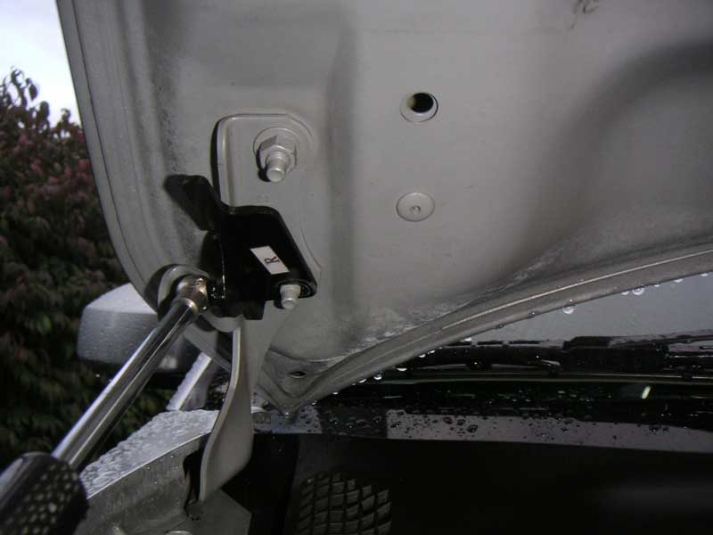
My first step was to use a 12mm socket to disconnect my NRG hood damper from the hood. Then using a couple of bungie cords, I suspended the hood from my eaves outside my garage to give me a lot more room to work under the the hood. If you have a helper, I'd suggest just removing the hood altogether to get it out of your way. As it was, it was raining so the hood kept the engine bay (mostly) dry.
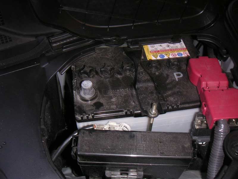
Next, I disconnected the battery ground using a 10mm socket. I made the mistake once on my '94 RX7 of NOT doing this. I ended up blowing the main fuse by shorting out the electrical system. There is a reason why most good mechanics do this. The Motordyne instructions call for removing the entire battery cover. I didn't do this just lifted the plastic lid. Very easy.
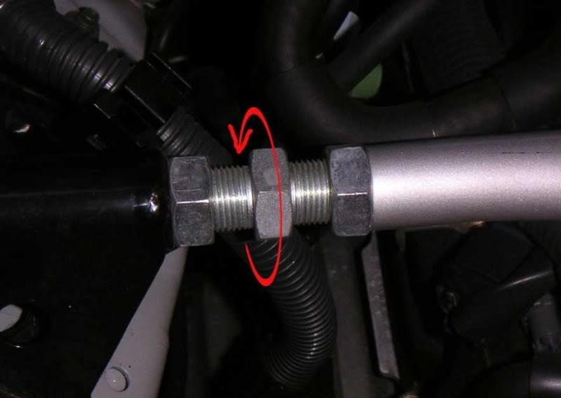
Next was to remove the strut bar. I'd never done this on the Z before and the Motordyne instructions are good. The MD instructions said to loosen the hex adjuster. Of course, I didn't know which way that was. Here is the direction to turn the adjust to loosen the strut. It has the effect of lengthening the strut bar. The Factory Service Manual says to loosen it 1.7 turns to remove the bar. MD suggests 1 turn. MD's suggestion is better.
Remove the Air Intake tube from the throttle body. Here we get to one of the parts where I'm an idiot. There are four things you have to do to remove it.
Loosen the first clamp near the front of the air tube near the MAF sensor.
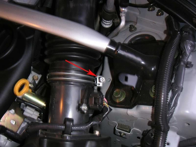
Loosen the clamp at the rear of the air tube by the throttle body.
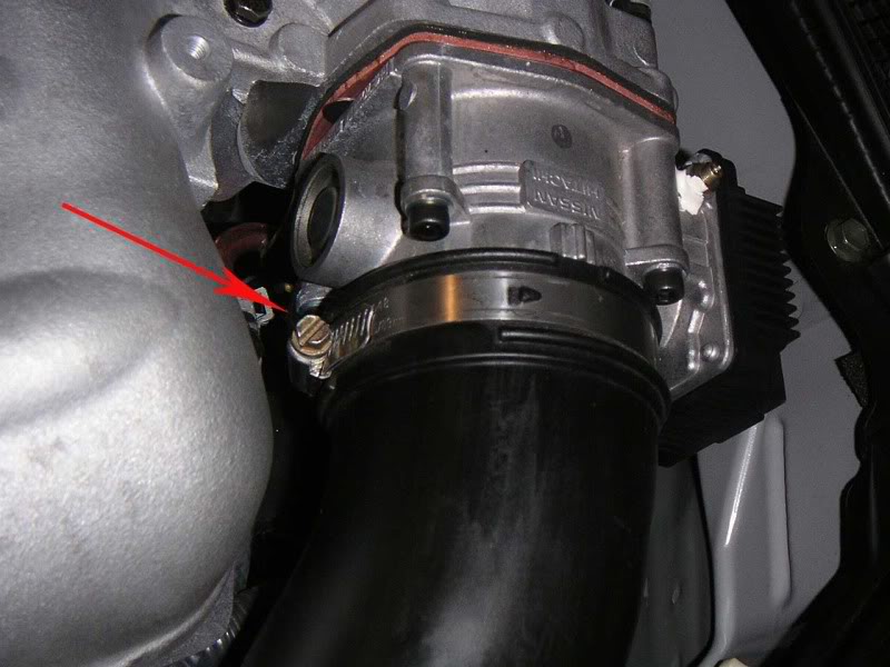
Then the two things that I forgot. The first is the Oil Vapor hose (which the MD instructions mention) and I just spaced on. It is located underneath the right side of the air tube. Remove the clamp and pull the hose off.
The second is a bracket that attaches the air tube to the lower plenum. I forget to get a picture of it so I ran out in the dark and snapped one. It is blurry but you will notice that I also forgot to replace the 10mm bolt. I did right after I snapped the picture. It may be that non 2006 Z's don't have this bracket.
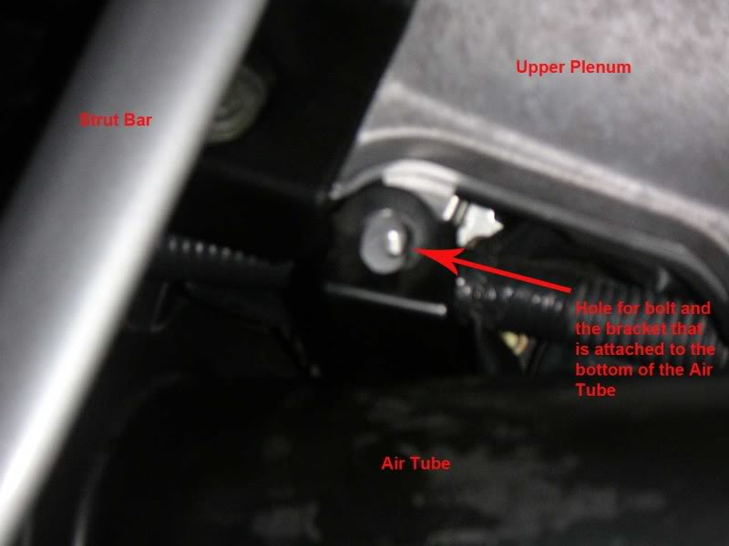
Believe me, the Air tube is a whole lot easier to take off after you have removed that bracket.
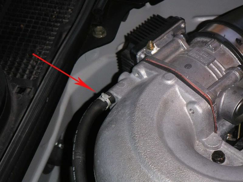
Disconnect vacuum line on battery side of Plenum.
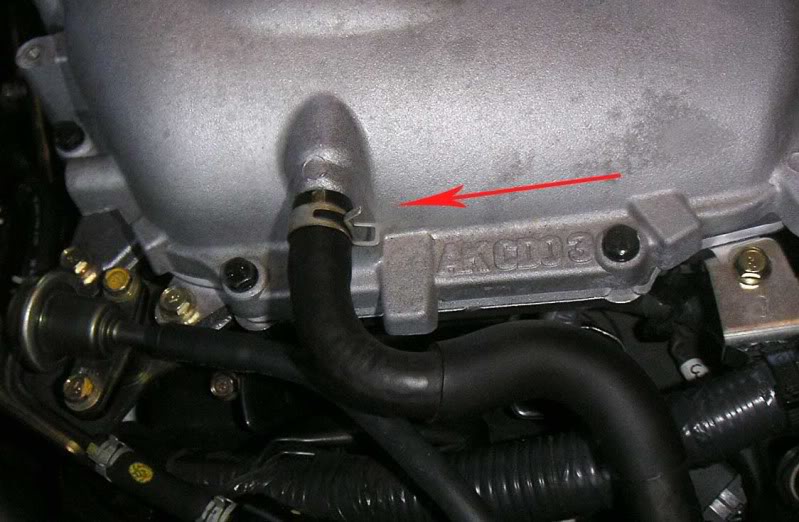
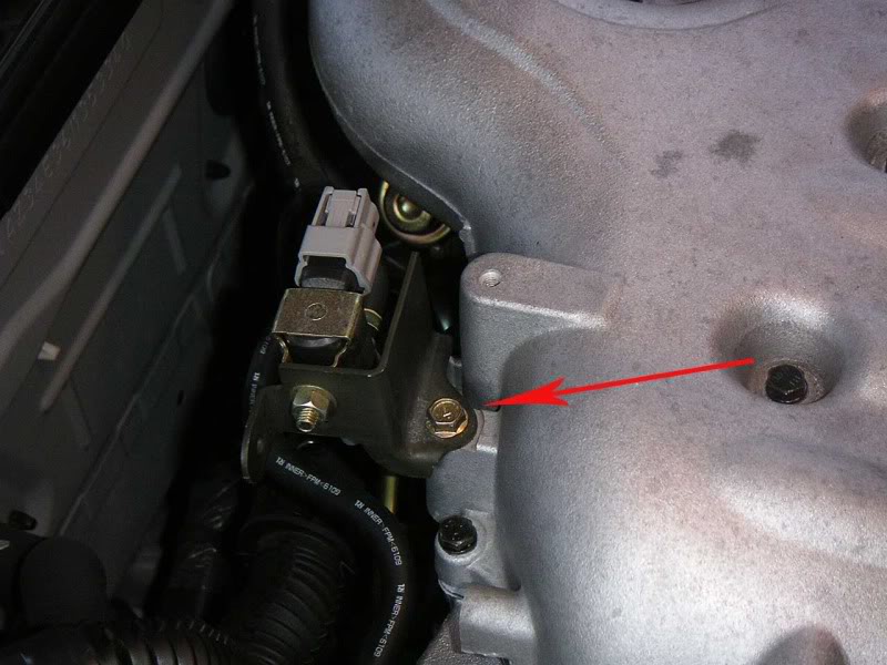
Unbolt the EVAP canister purge volume control solenoid valve bracket that is attached to the upper plenum on the rear of the plenum on the passenger side.
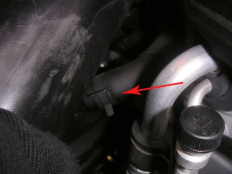
Remove the hose (I think it is a vacuum hose) from the back of the upper plenum right near the throttle body. This one is pretty easy to spot.
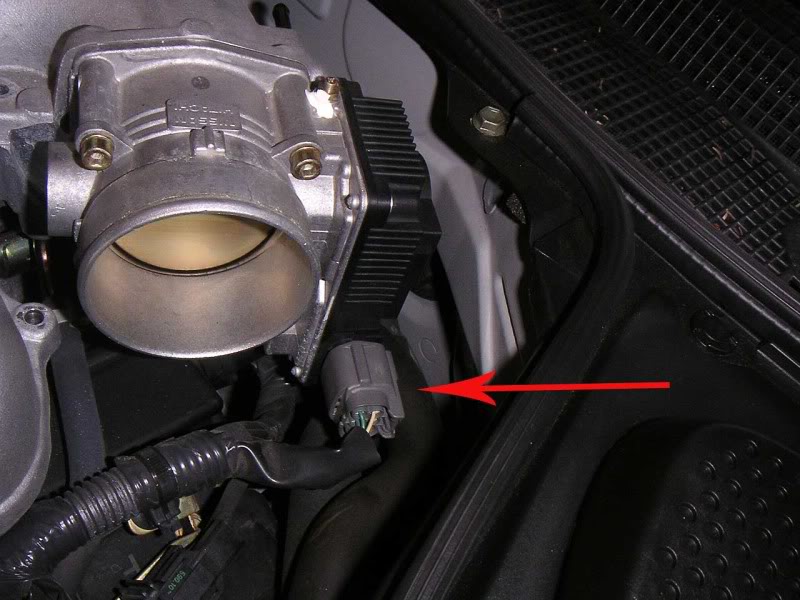
Unplug the electric connector from the throttle body on the drivers side.
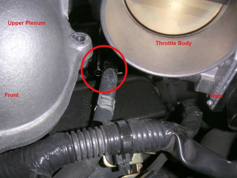
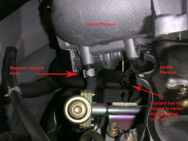
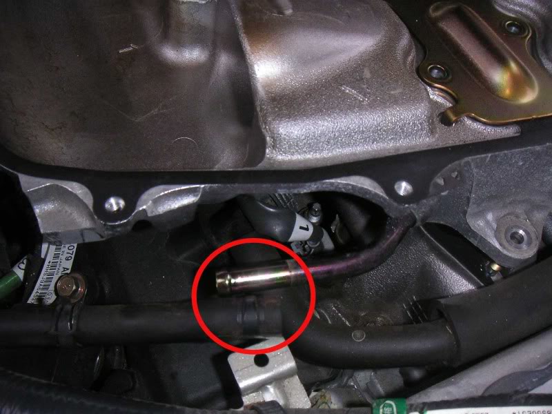
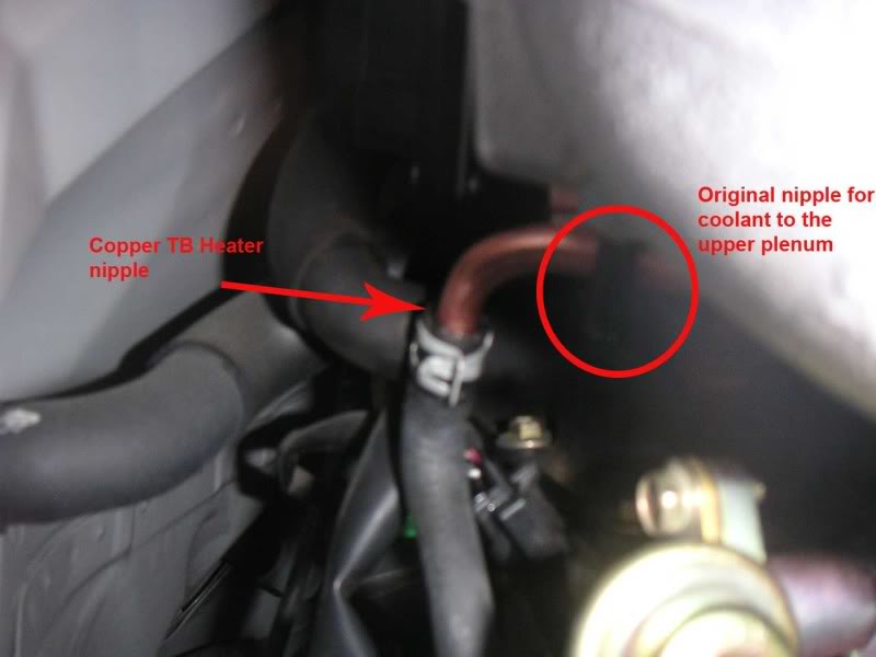
Now it starts to get more difficult. You need to remove the coolant line to the upper plenum. This isn't real easy to spot, a bit hard to reach, and even harder to photograph. It is underneath and to the left of the throttle body as you look at it from the drivers side. Here it is in the circle, the hose is disconnected in the picture.
Now you can follow MD instructions and remove the 16 10mm bolts, 2 10mm nuts, and 2 guide pins from the upper plenum. Following MDs suggestion, I was able to remove the guide pins using a 4mm socket. They also show you how to remove the pins using two 10mm nuts if you need to. I removed the
pins after I had removed the upper plenum.
One more hose to disconnect before you can remove the upper plenum. Here it would help to have a helper. From the passenger side, lift the upper plenum a little and look underneath the back of the upper plenum below the throttle body. There is another coolant line that is vertical. This needs to be removed.
Once that hose is disconnected, you can remove the upper plenum and set it aside. MD says to wipe out the inside of the upper plenum. Mine was pretty clean.
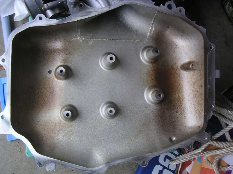
My lower plenum however had a fair amount of oil underneath the intake manifold collector. It may have something to do with the ~100 autocross runs that I did yesterday at club practice.
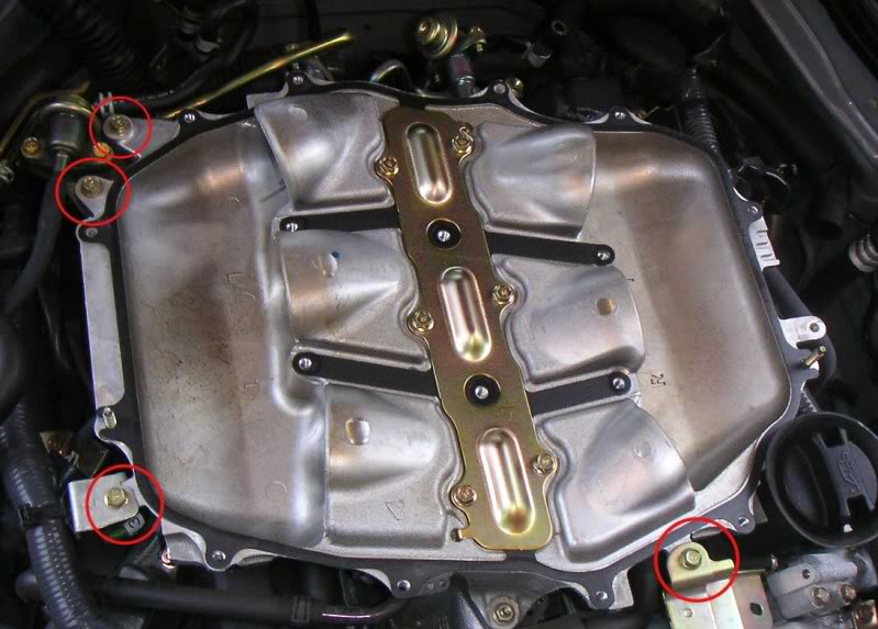
I now had to remove the lower plenum. Again, MD instructions are pretty good. Three brackets need to be removed from the lower plenum. One is attached with 2 bolts. All the bolts that have to be removed are shown here.
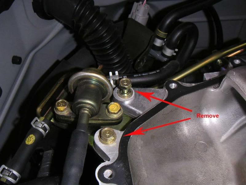
There is also a hose that connects to the lower plenum that needs to be disconnected. This is easy as it is right in the front of the plenum and is easy to reach. Shown here already disconnected.
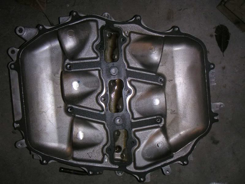
Then you can lift out the lower plenum and set it aside. I was installing the Aramid Manifold gasket. Remove the manifold gasket that is there and toss it. I didn't take any pictures here because it was pretty self-explanatory and it was starting to get windy and I didn't want anything blown into the engine. I oiled the new manifold gasket as shown on MDs installation video and figured out how it is supposed to be oriented.
Continued in next post....
I've got a 2006 MT GT Coupe. As you know, this has the RevUp engine. As such, just installing a spacer won't help much. You need to install the MREV2 lower plenum as well.
I went with the 5/16" Copper Iso Thermal Spacer by Motordyne as well as their lower plenum. They call it MREV2. I've heard nothing but good things about Motordyne products and service. I purchase the spacer kit and the MREV2 from two different vendors here on the board. Both of them provided good pricing and fast service. I like to support the vendors that make this site possible.
The instructions provided by Motordyne are really quite good and they also have a video of an install on their website. Most of you could do the job with no problem using those. I'm a bit slow however.
Unfortunately, I had to do this alone. For those of you who actually have friends, get one of them to give you a hand. It would have been a lot faster and a lot easier with an extra set.
My first step was to use a 12mm socket to disconnect my NRG hood damper from the hood. Then using a couple of bungie cords, I suspended the hood from my eaves outside my garage to give me a lot more room to work under the the hood. If you have a helper, I'd suggest just removing the hood altogether to get it out of your way. As it was, it was raining so the hood kept the engine bay (mostly) dry.
Next, I disconnected the battery ground using a 10mm socket. I made the mistake once on my '94 RX7 of NOT doing this. I ended up blowing the main fuse by shorting out the electrical system. There is a reason why most good mechanics do this. The Motordyne instructions call for removing the entire battery cover. I didn't do this just lifted the plastic lid. Very easy.
Next was to remove the strut bar. I'd never done this on the Z before and the Motordyne instructions are good. The MD instructions said to loosen the hex adjuster. Of course, I didn't know which way that was. Here is the direction to turn the adjust to loosen the strut. It has the effect of lengthening the strut bar. The Factory Service Manual says to loosen it 1.7 turns to remove the bar. MD suggests 1 turn. MD's suggestion is better.
Remove the Air Intake tube from the throttle body. Here we get to one of the parts where I'm an idiot. There are four things you have to do to remove it.
Loosen the first clamp near the front of the air tube near the MAF sensor.
Loosen the clamp at the rear of the air tube by the throttle body.
Then the two things that I forgot. The first is the Oil Vapor hose (which the MD instructions mention) and I just spaced on. It is located underneath the right side of the air tube. Remove the clamp and pull the hose off.
The second is a bracket that attaches the air tube to the lower plenum. I forget to get a picture of it so I ran out in the dark and snapped one. It is blurry but you will notice that I also forgot to replace the 10mm bolt. I did right after I snapped the picture. It may be that non 2006 Z's don't have this bracket.
Believe me, the Air tube is a whole lot easier to take off after you have removed that bracket.
Disconnect vacuum line on battery side of Plenum.
Unbolt the EVAP canister purge volume control solenoid valve bracket that is attached to the upper plenum on the rear of the plenum on the passenger side.
Remove the hose (I think it is a vacuum hose) from the back of the upper plenum right near the throttle body. This one is pretty easy to spot.
Unplug the electric connector from the throttle body on the drivers side.
Now it starts to get more difficult. You need to remove the coolant line to the upper plenum. This isn't real easy to spot, a bit hard to reach, and even harder to photograph. It is underneath and to the left of the throttle body as you look at it from the drivers side. Here it is in the circle, the hose is disconnected in the picture.
Now you can follow MD instructions and remove the 16 10mm bolts, 2 10mm nuts, and 2 guide pins from the upper plenum. Following MDs suggestion, I was able to remove the guide pins using a 4mm socket. They also show you how to remove the pins using two 10mm nuts if you need to. I removed the
pins after I had removed the upper plenum.
One more hose to disconnect before you can remove the upper plenum. Here it would help to have a helper. From the passenger side, lift the upper plenum a little and look underneath the back of the upper plenum below the throttle body. There is another coolant line that is vertical. This needs to be removed.
Once that hose is disconnected, you can remove the upper plenum and set it aside. MD says to wipe out the inside of the upper plenum. Mine was pretty clean.
My lower plenum however had a fair amount of oil underneath the intake manifold collector. It may have something to do with the ~100 autocross runs that I did yesterday at club practice.
I now had to remove the lower plenum. Again, MD instructions are pretty good. Three brackets need to be removed from the lower plenum. One is attached with 2 bolts. All the bolts that have to be removed are shown here.
There is also a hose that connects to the lower plenum that needs to be disconnected. This is easy as it is right in the front of the plenum and is easy to reach. Shown here already disconnected.
Then you can lift out the lower plenum and set it aside. I was installing the Aramid Manifold gasket. Remove the manifold gasket that is there and toss it. I didn't take any pictures here because it was pretty self-explanatory and it was starting to get windy and I didn't want anything blown into the engine. I oiled the new manifold gasket as shown on MDs installation video and figured out how it is supposed to be oriented.
Continued in next post....
Thread Starter
New Member
iTrader: (10)
Joined: Aug 2008
Posts: 990
Likes: 1
From: University Place, WA
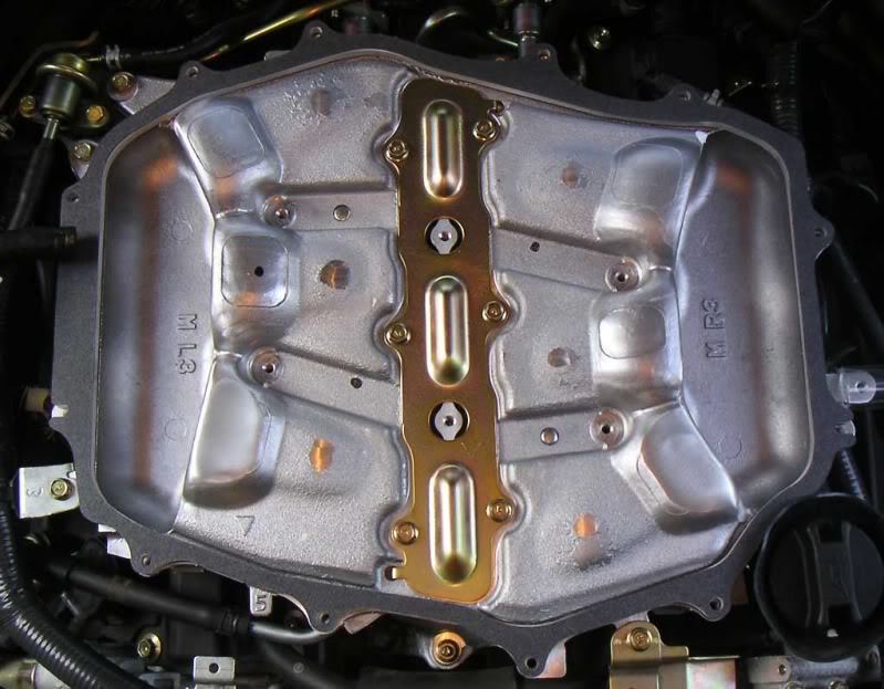
I used compressed air to blow out the MREV2 to make sure there was no dust or debri in it. It sets down on the manifold pretty easily using the two pins, front and rear, to align it. Replace the Intake Manifold Collector Cover (the metal piece that runs down the middle of the lower plenum) and you are ready to bolt it down following MDs instructions.
Motordynes instructions are very clear about how to torque down the bolts in an even way. They give the torque values in inch-lbs. My torque wrench is calibrated in foot-lbs. To convert from inch-lbs to foot-lbs, simply divide by 12. 12 inch-lbs are 1 foot-lbs. Here are the conversions from the specified inch-lbs to ft-lbs and Neuton Meters.
40 inch-lbs = 3.3 ft-lbs = 4.5 N-m
80 inch-lbs = 6.6 ft-lbs = 9.0 N-m
100 inch-lbs = 8.3 ft-lbs = 11.3 N-m
Since my torque wrench is only calibrated down to 5 ft-lbs, I used a nut driver with a 10mm socket to initially tighten the bolts. I tightened them only moderately with the nut driver then retorqued at 5 ft-lbs with my torque wrench, then again at 6.5 ft-lbs, and finally at 8.5 ft-lbs. MD instructions suggest that unless you are used to using your torque wrench that you should practice on something else first. I also strongly suggest this as I made that mistake on a prior car and ended up stripping threads. I now own a tap and die set.
Here is the MREV2 bolted in place, bracket and hose reattached, and the 5/16 spacer sitting in place.
Now it was time to install the Copper TB heater. I chose this over MDs regular Iso Thermal kit so I wouldn't have to worry about opening and closing the plenum coolant with changes in weather. With the Copper Throttle Body heater, engine coolant is used to keep the TB warm in cold weather but is isolated from the intake plenum to reduce heat soak. I wanted something I could install and forget about.
I didn't get any pictures of this process because it was really straightforward and MDs instructions are good. I would mention a couple of things that I ran into due to my own stupidity. The TB is connected to the plenum using bolts with a 5mm Allen head. MD warns that they are very tight and to use a good quality Allen wrench. I thought I would be clever and use my Allen head adapters for my socket wrench. However, because of the tight space, my Allen head wasn't perfectly lined up and I almost ruined one bolt. I then used an Allen wrench but had to use a hammer to tap the end of the Allen wrench deep enough into the bolt to get it to grab. In the end I was able to get all four bolts out.
The second issue was that I initially attempted to reuse the TB bolts after installing the copper TB heater. I failed to realize that MD does provide 4 new, longer bolts to use with this kit. I had the TB reassembled before I began to wonder. These bolts are not listed in MDs parts list and are not mentioned in the instructions. However, they are there and should be used.
Finally, MD gives torque specs for reattaching the TB. I have no idea how to come up with a specific torque value on an Allen wrench so I guessed.
With the TB reattached to the upper plenum, it was time to reinstall it. MD instructions are clear. I did run into one problem however. MD has plastic spacers for the interior of the upper plenum. One one side these have a cup-like configuration that the internal posts of the plenum are supposed to sit in.
On two of the posts on my plenum, the posts were too wide to fit inside that cup. This would have caused the plastic spacer to sit too high, or be too large, for the plenum to seat properly. It may be hard to tell but this picture shows that the width of the post is just a bit too wide to allow the cap to seat on it.
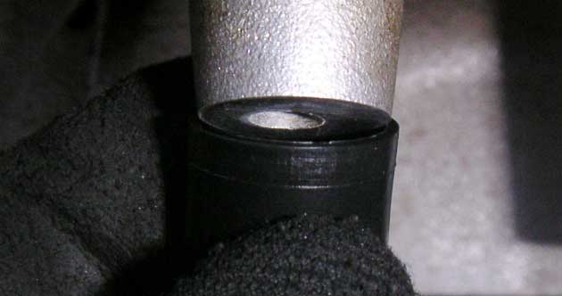
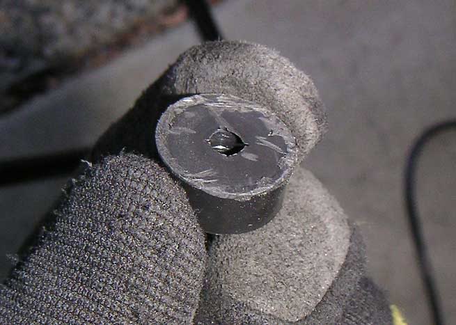
Tony from Motordyne engineering (Hydrazine on the forum) had sent me a PM telling me to call him if I had any questions. It was Saturday afternoon, but I called anyway. Tony answered the phone and I explained my problem. He explained that there are some manufacturing variations that occasionally happen with the stock cast plenums. He suggested I remove the lip of the cap so that the spacer would sit down on the end of the post. I really appreciated this example of customer service on the part of Motordyne Engineering.
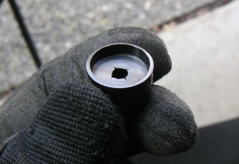
Anyway, a few minutes with a Dremel and the two spacers now looked like this. (it is actually smoother than it looks in the photo.
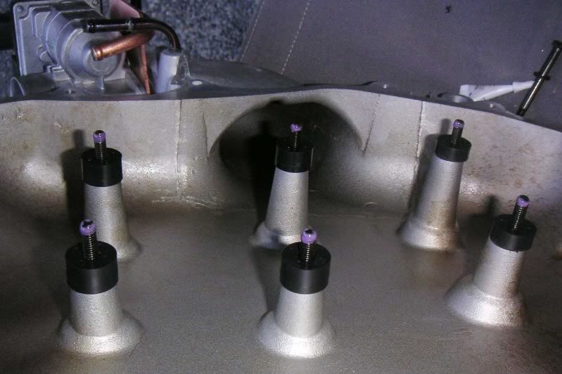
Here is the plenum with spacers in place and Locktite on the ends of the bolts. Notice the Copper TB heater on the back of the plenum. You can see where the coolant lines will be attached to the TB heater and not to the plenum.
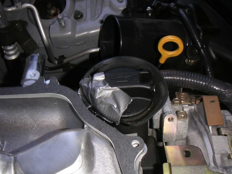
Now I was ready to put the upper plenum back on. One of the things that I noticed when I placed the 5/16 spacer on the lower plenum, was that the rubber flange around the oil fill cap kept getting in the way. I didn't want to pinch it betwenn the spacer and the upper plenum so I used a bit of duct tape to fold the flange out of the way. Doing this job by myself, this made it a lot easier to get the plenum placed.
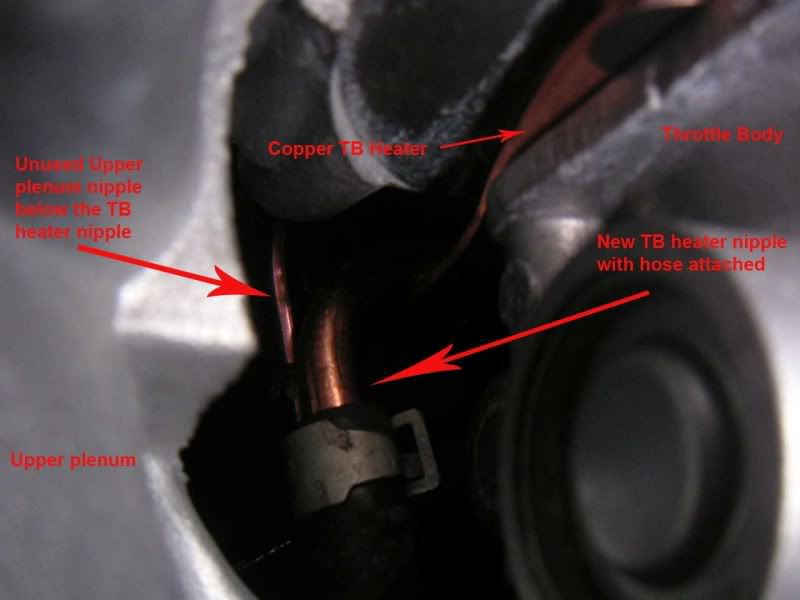
Putting the upper plenum back on was a pain in the backside. I didn't want to waste time since the Locktite was on the bolts. However, the nipple for the TB heater that is underneath the plenum has to be reattached. You can do it with the upper plenum sitting on the lower plenum and it is hard to put the hose on the nipple (the copper ones are a bit larger than the stock nipples) with one hand while holding the plenum up with the other. Here is where a helper would be a really good idea. Here is a poor pic of of the nose on the new nipple with the original plenum nipple to the right. Sorry about the blur but I was juggling at the time.
After that hose is on you can set the plenum down and start to bolt it on following MD instructions. After it is bolted down, then put the other coolant line on the other TB heater nipple. Again, this is tough due to the tight space and the larger nipple.
Next, replace the hoses and brackets that you removed before you took off the plenum. Don't forget to reconnect the electrical connection to the TB.
Replace your Air Intake tube and then reconnect the ground to the battery. Start the car and listen for any air leaks and look to make sure that there aren't any coolant leaks from the TB heater connections. If everything looks good, then replace the engine cover.
You will need to use the spacers that MD provided so that your strut bar clears your engine. Simply follow MD instructions and don't forget to tighten down the locking nuts on the strut bar after you have adjusted it.
After I had removed the upper and lower plenum, I took advantage of the extra space and replaced my spark plugs. Even with everything removed, that was still more of a pain than everything else combined.
I'm going to have a dyno done to compare with one I had done before installing the lower plenum and spacer. I'll post the results when I have them.
Dyno results are in. You can find them in this thread
Motordynes instructions are very clear about how to torque down the bolts in an even way. They give the torque values in inch-lbs. My torque wrench is calibrated in foot-lbs. To convert from inch-lbs to foot-lbs, simply divide by 12. 12 inch-lbs are 1 foot-lbs. Here are the conversions from the specified inch-lbs to ft-lbs and Neuton Meters.
40 inch-lbs = 3.3 ft-lbs = 4.5 N-m
80 inch-lbs = 6.6 ft-lbs = 9.0 N-m
100 inch-lbs = 8.3 ft-lbs = 11.3 N-m
Since my torque wrench is only calibrated down to 5 ft-lbs, I used a nut driver with a 10mm socket to initially tighten the bolts. I tightened them only moderately with the nut driver then retorqued at 5 ft-lbs with my torque wrench, then again at 6.5 ft-lbs, and finally at 8.5 ft-lbs. MD instructions suggest that unless you are used to using your torque wrench that you should practice on something else first. I also strongly suggest this as I made that mistake on a prior car and ended up stripping threads. I now own a tap and die set.
Here is the MREV2 bolted in place, bracket and hose reattached, and the 5/16 spacer sitting in place.
Now it was time to install the Copper TB heater. I chose this over MDs regular Iso Thermal kit so I wouldn't have to worry about opening and closing the plenum coolant with changes in weather. With the Copper Throttle Body heater, engine coolant is used to keep the TB warm in cold weather but is isolated from the intake plenum to reduce heat soak. I wanted something I could install and forget about.
I didn't get any pictures of this process because it was really straightforward and MDs instructions are good. I would mention a couple of things that I ran into due to my own stupidity. The TB is connected to the plenum using bolts with a 5mm Allen head. MD warns that they are very tight and to use a good quality Allen wrench. I thought I would be clever and use my Allen head adapters for my socket wrench. However, because of the tight space, my Allen head wasn't perfectly lined up and I almost ruined one bolt. I then used an Allen wrench but had to use a hammer to tap the end of the Allen wrench deep enough into the bolt to get it to grab. In the end I was able to get all four bolts out.
The second issue was that I initially attempted to reuse the TB bolts after installing the copper TB heater. I failed to realize that MD does provide 4 new, longer bolts to use with this kit. I had the TB reassembled before I began to wonder. These bolts are not listed in MDs parts list and are not mentioned in the instructions. However, they are there and should be used.
Finally, MD gives torque specs for reattaching the TB. I have no idea how to come up with a specific torque value on an Allen wrench so I guessed.
With the TB reattached to the upper plenum, it was time to reinstall it. MD instructions are clear. I did run into one problem however. MD has plastic spacers for the interior of the upper plenum. One one side these have a cup-like configuration that the internal posts of the plenum are supposed to sit in.
On two of the posts on my plenum, the posts were too wide to fit inside that cup. This would have caused the plastic spacer to sit too high, or be too large, for the plenum to seat properly. It may be hard to tell but this picture shows that the width of the post is just a bit too wide to allow the cap to seat on it.
Tony from Motordyne engineering (Hydrazine on the forum) had sent me a PM telling me to call him if I had any questions. It was Saturday afternoon, but I called anyway. Tony answered the phone and I explained my problem. He explained that there are some manufacturing variations that occasionally happen with the stock cast plenums. He suggested I remove the lip of the cap so that the spacer would sit down on the end of the post. I really appreciated this example of customer service on the part of Motordyne Engineering.
Anyway, a few minutes with a Dremel and the two spacers now looked like this. (it is actually smoother than it looks in the photo.
Here is the plenum with spacers in place and Locktite on the ends of the bolts. Notice the Copper TB heater on the back of the plenum. You can see where the coolant lines will be attached to the TB heater and not to the plenum.
Now I was ready to put the upper plenum back on. One of the things that I noticed when I placed the 5/16 spacer on the lower plenum, was that the rubber flange around the oil fill cap kept getting in the way. I didn't want to pinch it betwenn the spacer and the upper plenum so I used a bit of duct tape to fold the flange out of the way. Doing this job by myself, this made it a lot easier to get the plenum placed.
Putting the upper plenum back on was a pain in the backside. I didn't want to waste time since the Locktite was on the bolts. However, the nipple for the TB heater that is underneath the plenum has to be reattached. You can do it with the upper plenum sitting on the lower plenum and it is hard to put the hose on the nipple (the copper ones are a bit larger than the stock nipples) with one hand while holding the plenum up with the other. Here is where a helper would be a really good idea. Here is a poor pic of of the nose on the new nipple with the original plenum nipple to the right. Sorry about the blur but I was juggling at the time.
After that hose is on you can set the plenum down and start to bolt it on following MD instructions. After it is bolted down, then put the other coolant line on the other TB heater nipple. Again, this is tough due to the tight space and the larger nipple.
Next, replace the hoses and brackets that you removed before you took off the plenum. Don't forget to reconnect the electrical connection to the TB.
Replace your Air Intake tube and then reconnect the ground to the battery. Start the car and listen for any air leaks and look to make sure that there aren't any coolant leaks from the TB heater connections. If everything looks good, then replace the engine cover.
You will need to use the spacers that MD provided so that your strut bar clears your engine. Simply follow MD instructions and don't forget to tighten down the locking nuts on the strut bar after you have adjusted it.
After I had removed the upper and lower plenum, I took advantage of the extra space and replaced my spark plugs. Even with everything removed, that was still more of a pain than everything else combined.
I'm going to have a dyno done to compare with one I had done before installing the lower plenum and spacer. I'll post the results when I have them.
Dyno results are in. You can find them in this thread
Last edited by dhays; Oct 5, 2009 at 11:24 AM.

Thread Starter
New Member
iTrader: (10)
Joined: Aug 2008
Posts: 990
Likes: 1
From: University Place, WA


Trending Topics


Registered User
Joined: Apr 2009
Posts: 1
Likes: 0
From: Sioux Falls SD
First of all - THANK YOU. I printed your pics and info to use alongside the MD doc, very helpful for my install last week.
Did you also remove your copper TB isolator for the AutoX event? I've got a thread going over on g35driver asking for comments from other people who've installed that piece and I'm not get much feedback. My TB doesn't really heat up at all which I've confirmed with a Raytek minitemp gun. Ambient temps here in South Dakota are quite low which may have something to do with it. The temps I measure off the TB are almost exactly the same as the upper plenum right next to the TB which is not what I would expect. I've felt both ends of the copper fittings and they're super hot which indicates that coolant is definitely flowing. I have the bare copper side against the new Nissan gasket, followed by the TB which is the correct order.
Did you ever feel your TB after idling or driving to see how hot it got with the copper isolator installed?


Registered User
Joined: Mar 2013
Posts: 27
Likes: 0
From: Minnesota
Sorry for commenting on an old thread...but did most of you use the oem upper plenum gasket AND the 5/16" spacer, or just the 5/16" spacer? I've heard both and I'm not sure which is better/more commonly done. Any input is appreciated!

Thread
Thread Starter
Forum
Replies
Last Post
allmycarsdie
Engine & Drivetrain
15
May 13, 2016 04:38 PM