
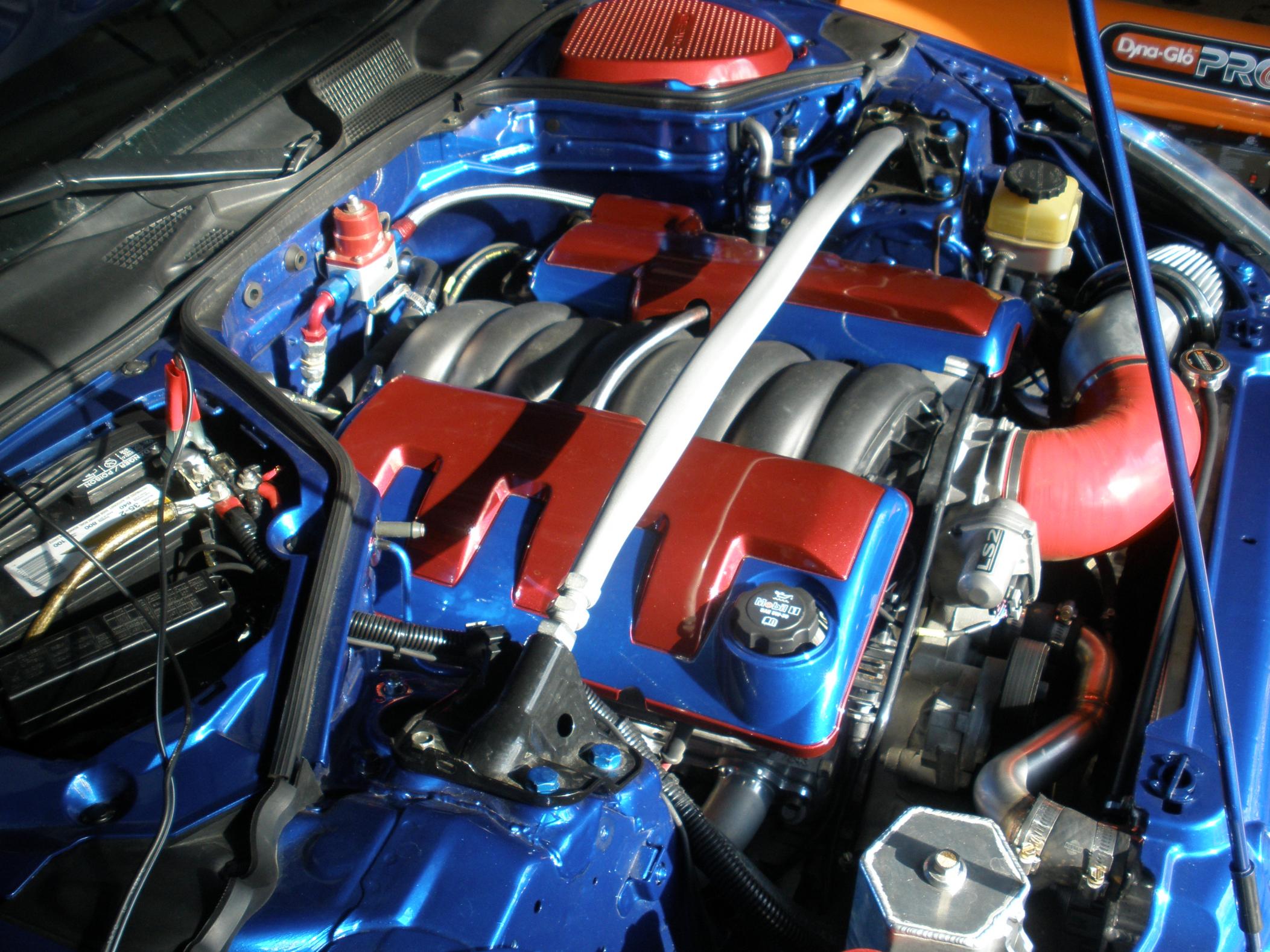
My SIKKY LS2 install thread


National Z Club President
iTrader: (15)
Joined: Sep 2008
Posts: 9,950
Likes: 2
From: the coolest place on earth
Got the car up on a lift today at Hill's. Went over all the nuts and bolts to make sure everything was tight. Found a small spot on the pass side header that was rubbing the frame and fixed that.
Found one concerning issue... the Cusco sway has made occasional contact with the front of the oil pan and rubbed a small spot in the side beads . My car is lowered all the way on the coilovers, so that may be the issue. I may have a blown shock up front as well, so that may be a contributing factor. We moved the sway to the rear holes (softer setting) and will see if that fixes it. If not, I may need to bring the ride height up or get a different sway. Frank suggested shorter end-links to restrict travel as well, but I'm not sure where to get those.
Found a small exhaust leak and also realized that JE butchered my APS exhaust. They cut the stock flanges off and put different ones on, which is NOT what I wanted. Now the exhaust is ruined if I ever want to resell it... THANKS SO MUCH BTW, the exhaust is leaking from their flange welds.
I also partially destroyed one of the V-band clamps at the header. Must have scraped it on something. The price of being low and baller I suppose.
Frank put my Zspeed underpan on, fits great and the cut out still lines up with the oil drain. Allows access to where my filter is as well. Down side was that they didn't debur it one bit and it will cut you to shreds if you don't handle it carefully.
The good news... Frank and I bled the old clutch fluid out and refilled with Motul and the clutch is MUCH improved in terms of pedal feel and softness. He also adjusted the pedal engagement down a touch from the very top.
About 800 miles since I brought it home and still loving it
Found one concerning issue... the Cusco sway has made occasional contact with the front of the oil pan and rubbed a small spot in the side beads
. My car is lowered all the way on the coilovers, so that may be the issue. I may have a blown shock up front as well, so that may be a contributing factor. We moved the sway to the rear holes (softer setting) and will see if that fixes it. If not, I may need to bring the ride height up or get a different sway. Frank suggested shorter end-links to restrict travel as well, but I'm not sure where to get those.Found a small exhaust leak and also realized that JE butchered my APS exhaust. They cut the stock flanges off and put different ones on, which is NOT what I wanted. Now the exhaust is ruined if I ever want to resell it... THANKS SO MUCH
BTW, the exhaust is leaking from their flange welds.I also partially destroyed one of the V-band clamps at the header. Must have scraped it on something. The price of being low and baller I suppose.
Frank put my Zspeed underpan on, fits great and the cut out still lines up with the oil drain. Allows access to where my filter is as well. Down side was that they didn't debur it one bit and it will cut you to shreds if you don't handle it carefully.
The good news... Frank and I bled the old clutch fluid out and refilled with Motul and the clutch is MUCH improved in terms of pedal feel and softness. He also adjusted the pedal engagement down a touch from the very top.
About 800 miles since I brought it home and still loving it

http://www.z1auto.com/prodmore.asp?m...ng&prodid=2886
Hope to see you on newyears

Registered User
Joined: Jul 2011
Posts: 5
Likes: 0
From: Sydney, Australia
Was going to suggest the Whiteline ones (Aussie site but available worldwide)
http://www.whiteline.com.au/product_..._number=KLC110
or the racecar ones!
http://www.whiteline.com.au/product_..._number=KLC010
The powergrid ones also look good (and a bit cheaper too).
http://www.whiteline.com.au/product_..._number=KLC110
or the racecar ones!
http://www.whiteline.com.au/product_..._number=KLC010
The powergrid ones also look good (and a bit cheaper too).


So I took a look at the sway bar position relative to the oil pan yesterday with the car on the ground and can see that the bar is maybe 1/4-3/8" away from the pan.... NOT GOOD.
I'm 90% sure I have at least one blown strut up front as well. I am considering swapping the factory struts back on to see if that helps since the TEINs will have to come out for repair anyway.
Any thoughts or input if the end links will solve this issue, or is it the ride height in general, or is it the Cusco sway, or is it the blown strut
Last resort would be to have a shop weld a couple of pieces to the crossmember that would stick out in front of the pan to act as bump stops for the sway bar.
So just like that the car is down till I get this sorted out
Decided to swap out to the factory struts, so I did it today in my garage... on my back... with hand tools  I am too old for this shizz.
Got the stockers back in and although the ride height looks a little weird the sway is further from the pan now. Definitely confirmed a blown strut or both in the front, the sharp rattle I had over bumps or transitions is now gone as is the pogoing effect I was feeling. Now I just have to find a way to get back to the corner of the pan and stick something to it to see if its still making contact or not.
Just like that... the car is back up
I am too old for this shizz.Got the stockers back in and although the ride height looks a little weird the sway is further from the pan now. Definitely confirmed a blown strut or both in the front, the sharp rattle I had over bumps or transitions is now gone as is the pogoing effect I was feeling. Now I just have to find a way to get back to the corner of the pan and stick something to it to see if its still making contact or not.
Just like that... the car is back up


Kinda OT, but any of you guys with VQ harness that you pulled out, any way anyone would sell me the driver's side VVT solenoid connector with a couple inches of wire still attached.
Mine got all buggered up when my cog belt snapped on my vortech and of course having cam issues on that side, so want to rewire that entire connection.
you'll never need again with the LS!
Thanks!
Mine got all buggered up when my cog belt snapped on my vortech and of course having cam issues on that side, so want to rewire that entire connection.
you'll never need again with the LS!
Thanks!

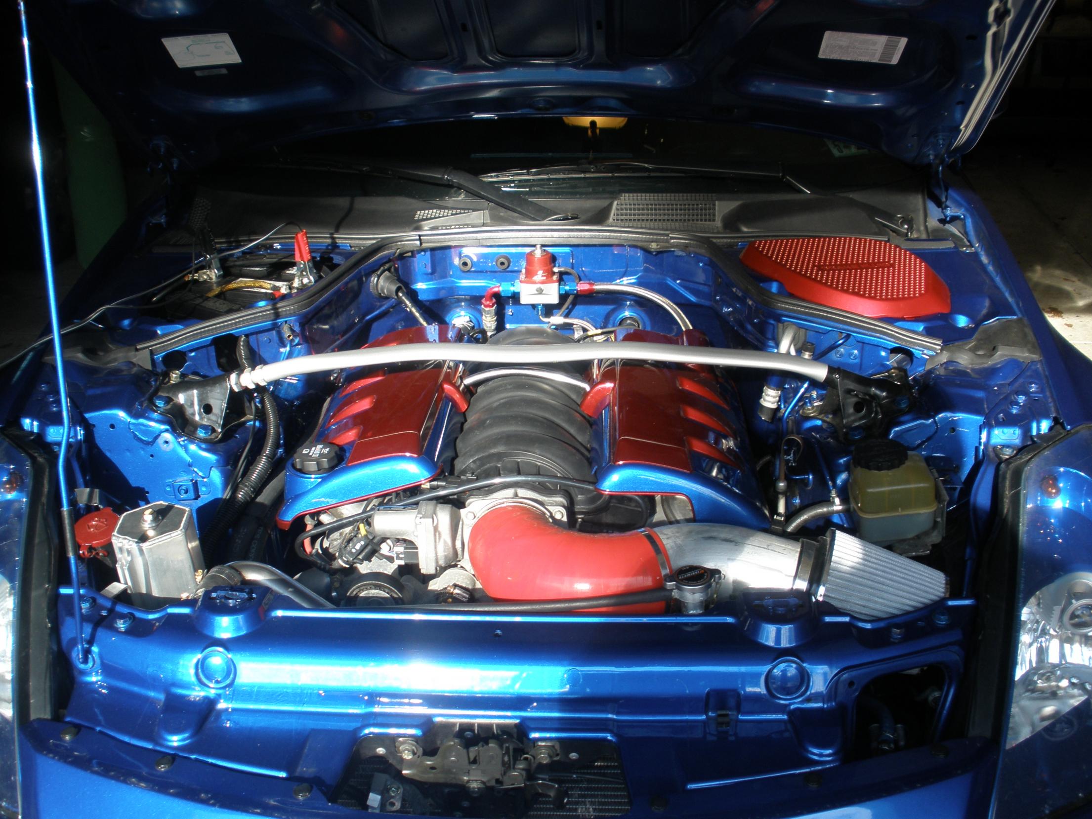
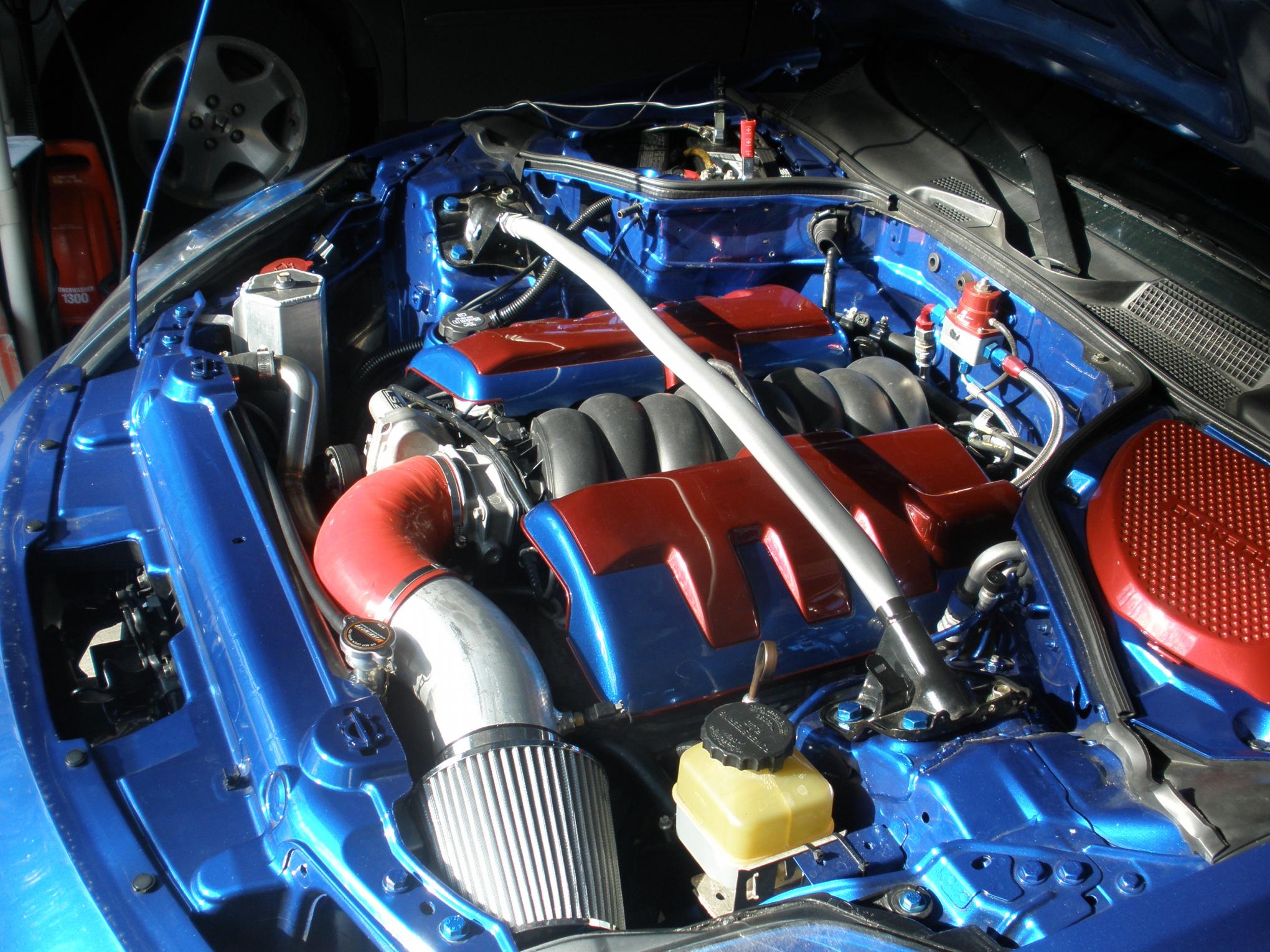


Battery charger? lol Hey where did you get your silicone bend off the TB? It looks like more than a 90* bend. I'm getting ready to order my parts but have been debating of doing a 90* or a 135* I'm digging the valve covers and impressed it all match so well.
I got a 135* and Franz cut it down to where it needed to be. The clearance is so tight that it had to bend more than 90* to be 4" all the way to intake.
looks amazing cass, btw what are you planning for another vq? i see that you have been asking around about some stock blocks lol
lOOKS GREAT CHRIS!
those engine covers dont look like they can hold power

Matches perfectly.
 - I buy the can when I get paint done because I know I have OCD issues with things looking a certain way.
yuo get any vaccuum leaks with that port unplugged from the brake booster?
- I buy the can when I get paint done because I know I have OCD issues with things looking a certain way.
yuo get any vaccuum leaks with that port unplugged from the brake booster?i went to siliconeintakes.com nice prices and awesome customer service
www.turbohoses.com
SHHH... its a secret!! I love my new setup and NOTHING will change this car back to a VQ.
SHHH... its a secret!! I love my new setup and NOTHING will change this car back to a VQ.
 I've already been told my car looks like Optimus Prime, I'm fine with it.
My VQ (revup) will be for sale in March if you're willing to wait.
i figured you where just looking to build a 287hp go cart or something =P
www.turbohoses.com
I got a 135* and Franz cut it down to where it needed to be. The clearance is so tight that it had to bend more than 90* to be 4" all the way to intake.
SHHH... its a secret!! I love my new setup and NOTHING will change this car back to a VQ.
Thanks Barney!!
Next mod is orange wheels
- I buy the can when I get paint done because I know I have OCD issues with things looking a certain way.