
S2K Engine Start Button install write-up


Operation of button:
To start the car, depress clutch, insert the key, turn it to the "on" position, position III, (position I being "OFF", II being ACC, III Being "ON, IV being "Start"), then hit the button to start the car instead of turning the key to the start position. To turn off the car, simply turn the key as usual. This is exactly how it works in the S2k (or Ferrari Enzo and many other exotics, for that matter).
To start the car, depress clutch, insert the key, turn it to the "on" position, position III, (position I being "OFF", II being ACC, III Being "ON, IV being "Start"), then hit the button to start the car instead of turning the key to the start position. To turn off the car, simply turn the key as usual. This is exactly how it works in the S2k (or Ferrari Enzo and many other exotics, for that matter).
i got my button in the mail last night and installed into the console, so I'll be wiring it up tonite.
My quick question is: do I need to unplug the battery for this or is this a safe install with the the battery still connected?
My quick question is: do I need to unplug the battery for this or is this a safe install with the the battery still connected?

Originally Posted by mahont
+1 ... any ideas?
Originally Posted by Voboy
http://www.nissanusa.com/altima07/
Maybe well be able to get our hands on this start button coming soon on the 07 altima. Looks good to me.
Maybe well be able to get our hands on this start button coming soon on the 07 altima. Looks good to me.
Interesting. Maybe the '07 Z will come with one as well.

Originally Posted by GTNPU Z
Well, if the red S2K button doesn't float your boat, you can always try to integrate the ones found on Lexus:


Registered User
Joined: Sep 2005
Posts: 7,951
Likes: 0
From: USA
Originally Posted by TurboSteve
new gauges as well

could someone post pics of the actual connections between the two red relay wires from the start button and the oem ignition wires(black/red and white/red)?
Last edited by Ztalker; Nov 6, 2006 at 07:44 PM.
Originally Posted by Ztalker
could someone post pics of the actually connections between the two red relay wires from the start button and the oem ignition wires(black/red and white/red)?
The two red wires from the relay connect as follows:
The wire coming from pin 87 of the relay will tap the black/red ignition wire at pin 3 of the ignition harness. Just strip a section of the wire and solder the wire from the relay to this point, then tape it up.
The wire from pin 30 of the relay is the starter wire. This connects to the white/red wire at pin 4 of the ignition harness in one of three ways: You can either:
A. tap the wire like you did the other one (this allows the car to start with either the key or the button).
B. Cut the wire and make the connection on the starter side and tape up the cut end leading to the connector. (this disables the key from starting the car and makes the button the only way to start it).
C. Cut the wire and wire it as in choice B, while also adding a wired two position (on/off) interrupt switch between the cut ends of the starter wire. This allows you to choose to disable/enable the key's ability to start the car at the flick of a switch. You will solder two wires to the cut end of the white/red wire leading to the starter: one red wire from pin 30 of the relay and one from the interrupt switch. The other wire from the interrupt swith will connect to the cut end of the white/red wire going into the connector.
I really don't know any way to explain it more clearly...
Last edited by MustGoFastR; Nov 11, 2006 at 08:26 PM.
Registered User
Joined: Sep 2005
Posts: 7,951
Likes: 0
From: USA
^thanks for taking the time again and explain to an idiot like me...i really appreciate it. If only i could see a picture of the soldered wires ...a picture is worth a thousand words i guess. So the (pin 30) wire is soldered to both the red/white wires and the (pin 87) wire is soldered to both black/white wires at the harness all together.
Originally Posted by Ztalker
^thanks for taking the time again and explain to an idiot like me...i really appreciate it. If only i could see a picture of the soldered wires ...a picture is worth a thousand words i guess. So the (pin 30) wire is soldered to both the red/white wires and the (pin 87) wire is soldered to both black/white wires at the harness all together.
These ar ethe two wires you use at the connector:

For the pin 87 wire going to the black/red wire, you don't cut the black red wire into two; you just strip off some of the insulation and solder the pin 87 wire from the relay to that point. You kind of make a "T" with the wires.
For the pin 30 wire from the relay going to the white/red wire, it depends on how you wnat it hooked up as to whether you cut it or not; the various ways are described above. However you do it, though, the pin 30 wire from the relay only connects at one point. You can tap like the pin 87 wire or you can cut the white/red wire and connect the pin 30 wire to the cut end going frther into the car (to the starter), not the connector.
I'd take a pic if I could, but that would require alot of disassembly and unwrapping of wires, etc.
In the picture below, the red wire ruinning into the loom is the pin 87 wire that is tapping into the black/red wire. Behind that, you see the cut end of the white/red wire running to the starter with the red pin 30 wire connected to it. The blue wire also connected there is from the optional switch. Right behind the connector, you see the other blue wire from the switch taped up; it is connected to the cut end of the white/red wire going into the connector. If you don't want the switch, just omit those blue wires from the pic and you have the setup for button start and disabled key start. If you want to start with either key or button with no switch, you don't cut the white/red wire at all; you tap it like the other one.


w00t! thanks for the great DIY man!
Here's my button with the Evo-R carbon fiber dash kit..
1. planning it out.. I just did the lazyman approach and traced the top of button itself Lots of maskng tape to make sure i don't crack the carbon fiber..
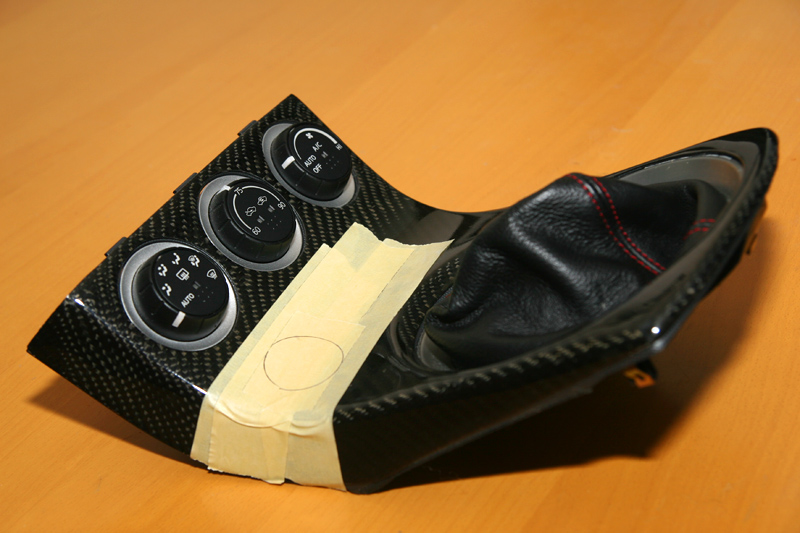
2. Not the neatest hole but a very snug fit and it's all covered up anyways
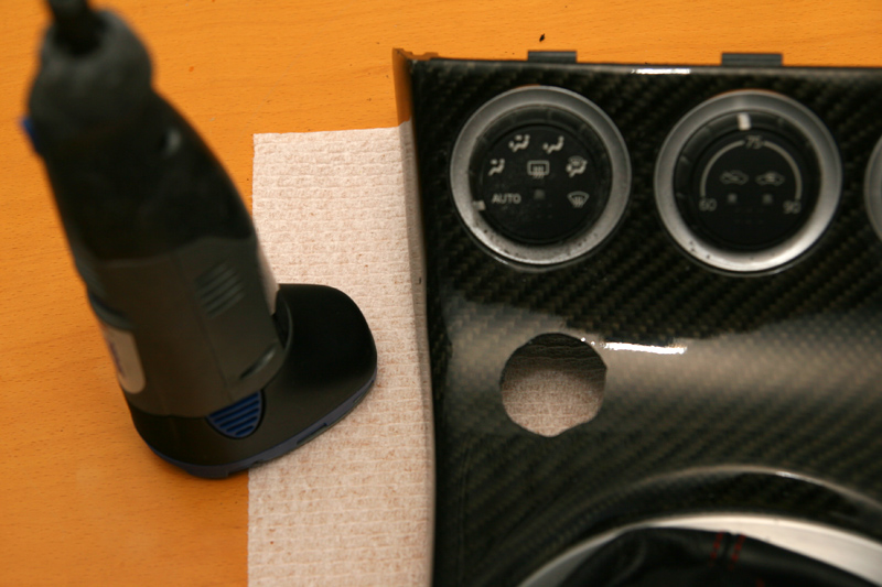
3. I wrapped the top of my button with black electrical tape so it's not shiny.. It makes the gap not appear as bad IMHO.. it's being held in the back with epoxy glue and 3M tape.. sucker is not moving lol
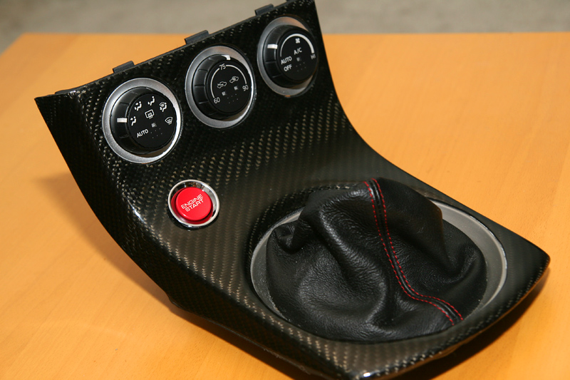
4. Mine must have been installed a tad bit lower because I didn't have to dremel that plastic support to make it fit!
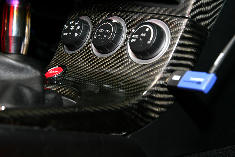
5. Taaadaaa finished!
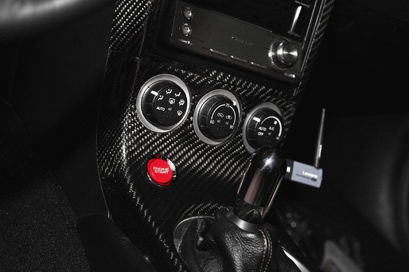
--mike
Here's my button with the Evo-R carbon fiber dash kit..
1. planning it out.. I just did the lazyman approach and traced the top of button itself
Lots of maskng tape to make sure i don't crack the carbon fiber..2. Not the neatest hole but a very snug fit and it's all covered up anyways
3. I wrapped the top of my button with black electrical tape so it's not shiny.. It makes the gap not appear as bad IMHO.. it's being held in the back with epoxy glue and 3M tape.. sucker is not moving lol
4. Mine must have been installed a tad bit lower because I didn't have to dremel that plastic support to make it fit!
5. Taaadaaa finished!
--mike
Originally Posted by THE TECH
You don't need to unplug the battery.

--mike
Originally Posted by leemik
This is bad information.. Please unplug the battery .. a friend of mine did his this week on his G35 and ***SPARK****!!!.. he needed to buy a new $20 main fuse from the dealer..
--mike
--mike
Hmm, that sucks. He must have crossed some wires or grounded something he shouldn't have or turned something on while working on it or something... I'll add a note to the write-up.

