
Tein inner and outer tie rod replacement


Thread Starter
Registered User
Joined: Nov 2008
Posts: 82
Likes: 1
From: Saratoga Springs, Ny
After doing some searching for a DIY for replacing the tie rods on the Z, coming up empty handed and frustrated, I have accomplished the repair and documented it for this DIY.
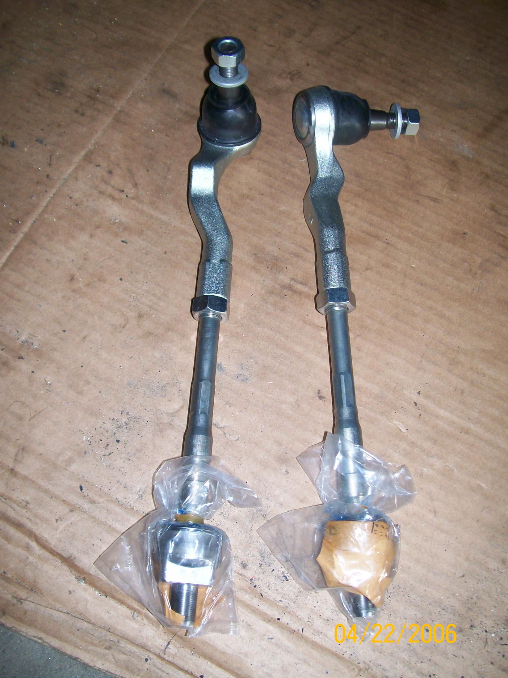
The Tie rods that I chose to use are the Tien rods with increased steering angle (if the insert is used-which I use).
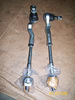
The Tie rods are sold by a bunch of different companies and are sold in pairs, inner and outer tie rods. It�s a good engineering practice and idea to replace both the inner and outer tie rod ends at the same time. This will keep your ride on the streets and shreddin the curves instead of on the rack for what seems like the same maintenance.
Tools required:
Tire iron Needle nose pliers
19mm socket, 3/8�� drive 3/8� socket wrench
3/8� extension-6� in length Locking wire
Hammer Small and medium flat head screwdrivers
Large open end adjustable wrench (Cressent or Ford or even box end, idk what size though)
Large breaker bar
1.) First thing�s first, we need to get the car as far off the ground as your bottle jack or floor jack will let you. You can even get it up far enough and use a 2�X4� or the like to get some extra headroom. You will be working from under the car for a portion of this and it makes it easier.
NOTE: It is imperative that you set the wheels straight and DO NOT MOVE THEM after this. Otherwise, the toe alignment is going to be wickedly off. (if you use the tein inner tie rods and opt to use the spacers to obtain the maximum steering angle, then you are going to need to account for that or get a realignment performed.)
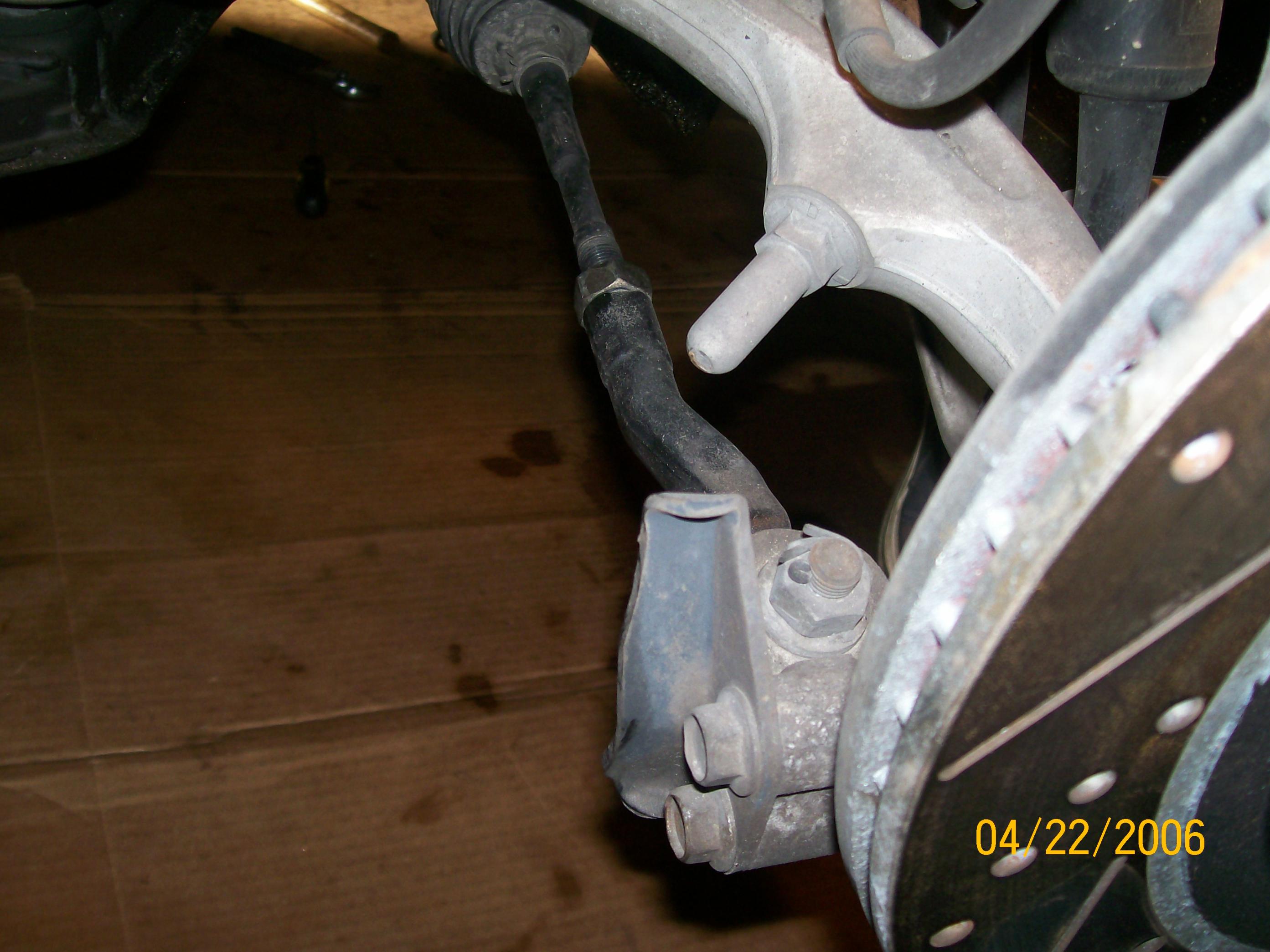
2.) Now, remove the tire to get the most area for action� be careful not to move the steering rack and pinion, steering wheel or the tires/wheel hubs themselves as mentioned above. Set the wheel aside as well as the wheel lugs. It should look like this:
I worked from the hub in, this prevents as much changing the steering rack and pinion position as possible. So start here
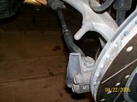
This is the passenger side, you can see there�s a steering stop bolted to the hub/spindle. Most people that use the tein rods seem to think that grinding the bump stop above it is a more suitable solution. I�m going to change mine out for one that has more area to travel-it�s just plate metal.
3.) There�s a cotter pin through the nut that secures the outer tie rod to the Steering hub, with the needle nose pliers, unbend it as much as possible and try to push it back through the hole in the stud. (the FSM says to replace these parts, cotter pins aren�t dreadfully expensive so do it. Besides the Tein kit comes with new ones anyway.) With the 19mm Socket, extension and breaker bar, break the torque on the nut.
Note: You will most likely hear a loud POP or SNAP. You broke the torque on the nut and stud, not your drive on your breaker bar (or adapter).
Grab the ratchet and remove the nut, but not all the way. Leave the nut on so that it is flush with the end of the stud. An easy way to remove the outer tie rod from the steering hub is to tap it out with a hammer. You may also use a puller tool, but this way is effective, quick and I didn�t care about the stock outer tie rods anyway. This may also POP or SNAP out of the knuckle, no fear, all is still well.
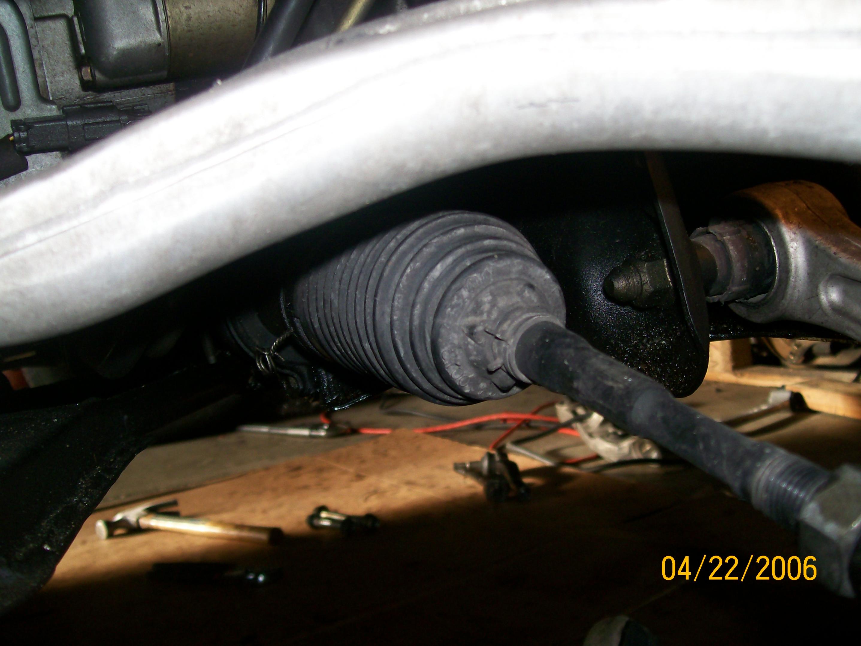
4.) Next remove the clamp on the dust boot and move the clamp as far down the inner rod as possible.
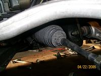
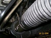
With your needle nose pliers, remove the locking wire on the other end of the dust boot and slide the dust boot down to expose the steering rack and the ball end of the inner tie rod.
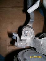
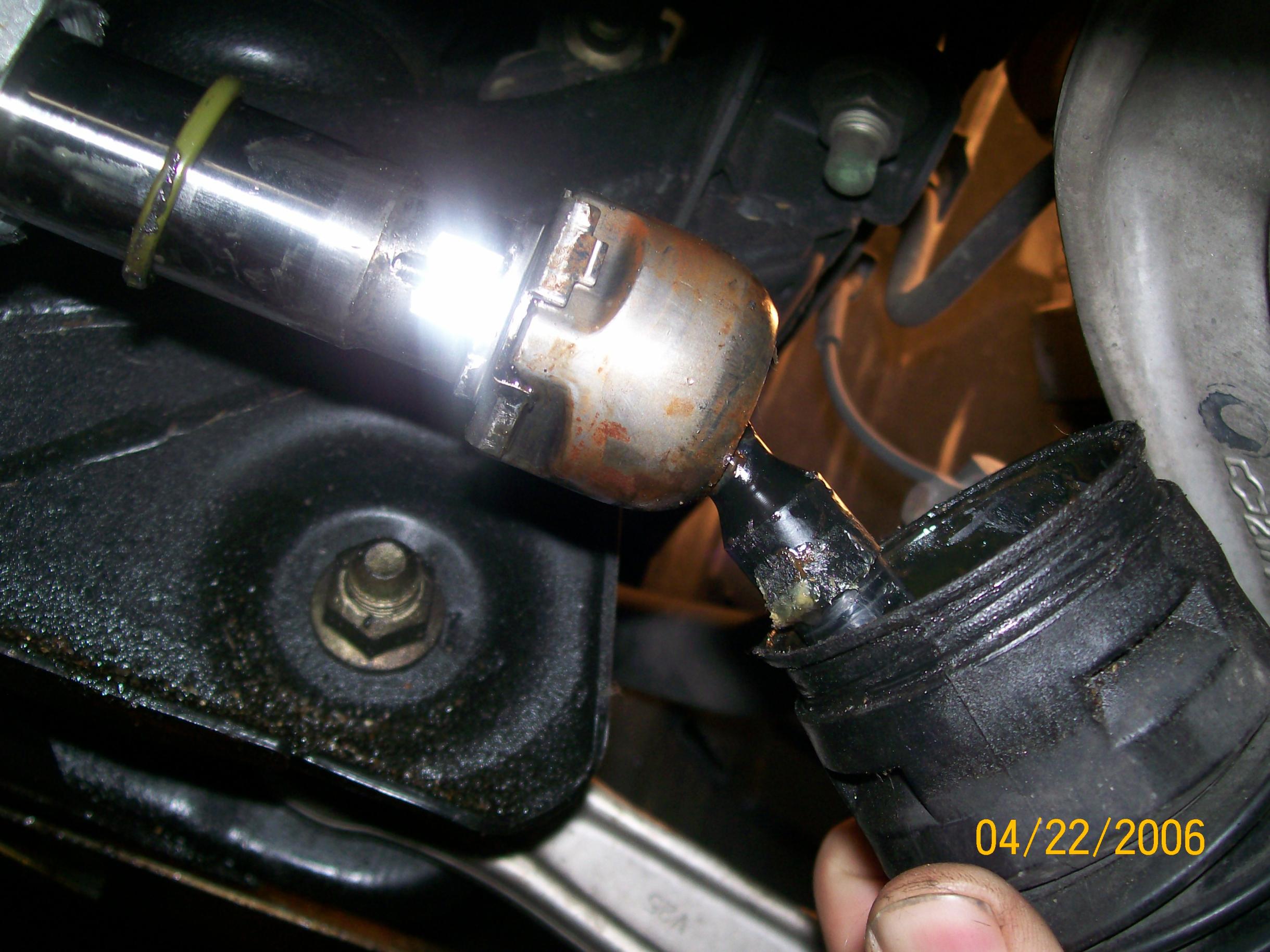
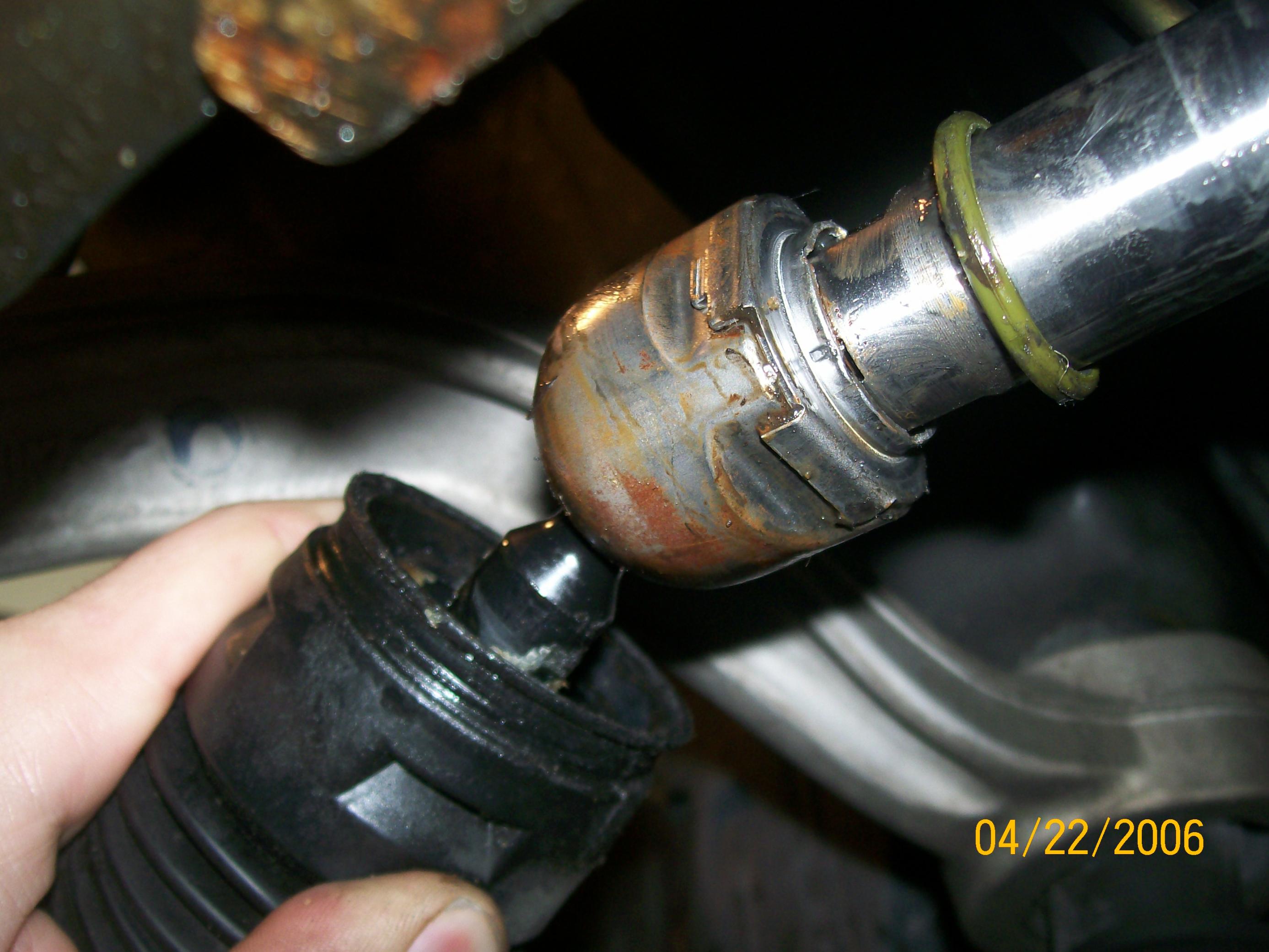
5.) Next step involves removing the retaining �washer� for the inner tie rod. This is a piece of sheet metal that is bent to clip on all 4 sides of the inner rod knuckle and then is staked to prevent it from loosening as well. Note the green O-ring in the previous picture-it acts to seal or hold this in place as well, as far as I can tell at least. Take a flat blade screwdriver and begin to bend the locking washer at the corners, working each side up and off of the flat/squared portion of the inner tie rod knuckle. Once all sides are loosened, attempt to un-stake the round part of the washer. If you cannot achieve this, pushing the washer as far back as possible will also allow the removal of the inner tie rod but makes using a wrench more difficult. In the picture below you can see the staked portion of the washer and the flat machined surfaces for using a wrench. These are normal right hand threads, so it�s righty tighty and lefty loosey.
6.) You should have been able to remove the entire tie rod assembly without changing the length of it, therefore, assembling the new tein rods should be easier since you can match it up before installing-remember it�s going to require some adjustment if you�re utilizing the steering angle spacers for added steering angle.
Transfer over the dust boot, dust boot clip and lock washer onto the new rod and assemble in the reverse order of the disassembly.
NOTE: If you are utilizing the steering angle spacer, the lock washer will not work adequately and should be reinforced with a lock collar or something similar (ie, hose clamp, split collar, etc.)
NOTE: When assembling the inner rod into the steering rack, use a small amount of thread lock on the threads to prevent the tie rod from unthreading. It is imperative that it is a medium duty thread lock to prevent unthreading, yet weak enough that it doesn�t permanently seal the threads together, preventing future repair.
7.) Once the inner tie rod is inserted into the steering rack, replace the boot and boot clamp. Use enough lockwire to secure the inboard portion of the boot onto the steering rack by wrapping it around the boot twice and then twisting with lockwire pliers until it is braided aprox 2-3� long. This will ensure that the boot is securely fastened and will not allow any dirt of debris into the steering rack.
8.) Reinstall the steering knuckle end of the tie rod into the front steering hub and use the new hardware provided, torque the nut to: XXX IN-LBS/XX FT-LBS.
9.) At this point, you are able to reinstall the wheels and lower the car back to the ground, however, attempt to get the tires as straight with as little toe as possible so that driving to the alignment rack/shop doesn�t murder your tires. A ball park means of achieving as little toe as possible is to use a square and a tape measure. Center the steering wheel and place the square on the wheel to set one side of the alignment, from this position, measure the front outside of the tire to the inside of the opposite tire. To get the toe as zero as possible, attempt to get the same measurement on the back side of the tire as well, meaning, measure the back outside of the first tire to the inside of the opposite tire � attempting to make the front and rear measurements equal. This will result in a very general �zero� toe setup that should allow you to get to the tire shop with as little wear as possible-if you have to drive the vehicle instead of tow it.
The Tie rods that I chose to use are the Tien rods with increased steering angle (if the insert is used-which I use).
The Tie rods are sold by a bunch of different companies and are sold in pairs, inner and outer tie rods. It�s a good engineering practice and idea to replace both the inner and outer tie rod ends at the same time. This will keep your ride on the streets and shreddin the curves instead of on the rack for what seems like the same maintenance.
Tools required:
Tire iron Needle nose pliers
19mm socket, 3/8�� drive 3/8� socket wrench
3/8� extension-6� in length Locking wire
Hammer Small and medium flat head screwdrivers
Large open end adjustable wrench (Cressent or Ford or even box end, idk what size though)
Large breaker bar
1.) First thing�s first, we need to get the car as far off the ground as your bottle jack or floor jack will let you. You can even get it up far enough and use a 2�X4� or the like to get some extra headroom. You will be working from under the car for a portion of this and it makes it easier.
NOTE: It is imperative that you set the wheels straight and DO NOT MOVE THEM after this. Otherwise, the toe alignment is going to be wickedly off. (if you use the tein inner tie rods and opt to use the spacers to obtain the maximum steering angle, then you are going to need to account for that or get a realignment performed.)
2.) Now, remove the tire to get the most area for action� be careful not to move the steering rack and pinion, steering wheel or the tires/wheel hubs themselves as mentioned above. Set the wheel aside as well as the wheel lugs. It should look like this:
I worked from the hub in, this prevents as much changing the steering rack and pinion position as possible. So start here
This is the passenger side, you can see there�s a steering stop bolted to the hub/spindle. Most people that use the tein rods seem to think that grinding the bump stop above it is a more suitable solution. I�m going to change mine out for one that has more area to travel-it�s just plate metal.
3.) There�s a cotter pin through the nut that secures the outer tie rod to the Steering hub, with the needle nose pliers, unbend it as much as possible and try to push it back through the hole in the stud. (the FSM says to replace these parts, cotter pins aren�t dreadfully expensive so do it. Besides the Tein kit comes with new ones anyway.) With the 19mm Socket, extension and breaker bar, break the torque on the nut.
Note: You will most likely hear a loud POP or SNAP. You broke the torque on the nut and stud, not your drive on your breaker bar (or adapter).
Grab the ratchet and remove the nut, but not all the way. Leave the nut on so that it is flush with the end of the stud. An easy way to remove the outer tie rod from the steering hub is to tap it out with a hammer. You may also use a puller tool, but this way is effective, quick and I didn�t care about the stock outer tie rods anyway. This may also POP or SNAP out of the knuckle, no fear, all is still well.
4.) Next remove the clamp on the dust boot and move the clamp as far down the inner rod as possible.

With your needle nose pliers, remove the locking wire on the other end of the dust boot and slide the dust boot down to expose the steering rack and the ball end of the inner tie rod.
5.) Next step involves removing the retaining �washer� for the inner tie rod. This is a piece of sheet metal that is bent to clip on all 4 sides of the inner rod knuckle and then is staked to prevent it from loosening as well. Note the green O-ring in the previous picture-it acts to seal or hold this in place as well, as far as I can tell at least. Take a flat blade screwdriver and begin to bend the locking washer at the corners, working each side up and off of the flat/squared portion of the inner tie rod knuckle. Once all sides are loosened, attempt to un-stake the round part of the washer. If you cannot achieve this, pushing the washer as far back as possible will also allow the removal of the inner tie rod but makes using a wrench more difficult. In the picture below you can see the staked portion of the washer and the flat machined surfaces for using a wrench. These are normal right hand threads, so it�s righty tighty and lefty loosey.
6.) You should have been able to remove the entire tie rod assembly without changing the length of it, therefore, assembling the new tein rods should be easier since you can match it up before installing-remember it�s going to require some adjustment if you�re utilizing the steering angle spacers for added steering angle.
Transfer over the dust boot, dust boot clip and lock washer onto the new rod and assemble in the reverse order of the disassembly.
NOTE: If you are utilizing the steering angle spacer, the lock washer will not work adequately and should be reinforced with a lock collar or something similar (ie, hose clamp, split collar, etc.)
NOTE: When assembling the inner rod into the steering rack, use a small amount of thread lock on the threads to prevent the tie rod from unthreading. It is imperative that it is a medium duty thread lock to prevent unthreading, yet weak enough that it doesn�t permanently seal the threads together, preventing future repair.
7.) Once the inner tie rod is inserted into the steering rack, replace the boot and boot clamp. Use enough lockwire to secure the inboard portion of the boot onto the steering rack by wrapping it around the boot twice and then twisting with lockwire pliers until it is braided aprox 2-3� long. This will ensure that the boot is securely fastened and will not allow any dirt of debris into the steering rack.
8.) Reinstall the steering knuckle end of the tie rod into the front steering hub and use the new hardware provided, torque the nut to: XXX IN-LBS/XX FT-LBS.
9.) At this point, you are able to reinstall the wheels and lower the car back to the ground, however, attempt to get the tires as straight with as little toe as possible so that driving to the alignment rack/shop doesn�t murder your tires. A ball park means of achieving as little toe as possible is to use a square and a tape measure. Center the steering wheel and place the square on the wheel to set one side of the alignment, from this position, measure the front outside of the tire to the inside of the opposite tire. To get the toe as zero as possible, attempt to get the same measurement on the back side of the tire as well, meaning, measure the back outside of the first tire to the inside of the opposite tire � attempting to make the front and rear measurements equal. This will result in a very general �zero� toe setup that should allow you to get to the tire shop with as little wear as possible-if you have to drive the vehicle instead of tow it.


Registered User
Joined: Sep 2009
Posts: 2,335
Likes: 5
From: Georgia
Where do you put the insert that increases the steering angle?
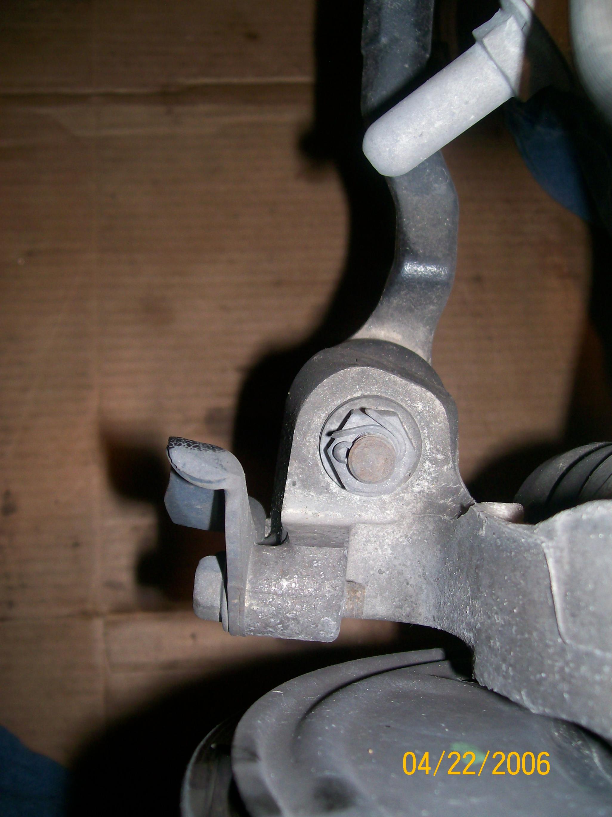
I thought the steering angle was controlled by the stops on the knuckle and lower control arm shown here:
BTW, there's a proper way to install and twist the wire holding the boot. Apparently the direction of wrapping and twisting is important. It's spelled out in the service manual section PS.
I really think it's best to have the car aligned after replacing those parts. It doesn't take much error in measurement to throw the alignment off enough to mess up your tires.
Last edited by winchman; Oct 3, 2011 at 12:39 PM.
Thread Starter
Registered User
Joined: Nov 2008
Posts: 82
Likes: 1
From: Saratoga Springs, Ny
the steering angle is changed by a sleeve on the rack side of the inner rod. It's a small brass bushing that goes over the threads that will thread into the rack. I will see if i can't find a picture of it in the camera. This is why it is important to put thread lock on the inner tie rod as it goes into the rack, since the "Lock washer" doesn't have any place to be staked, preventing movement.


Registered User
Joined: Sep 2009
Posts: 2,335
Likes: 5
From: Georgia
If the insert goes between the end of the rack and the inner end of the tie rod, it shifts the entire tie rod assembly outward. You'll have to shorten the distance from the inner end of the tie rod to the outer end, or the car will have too much toe-in.
Apparently, the insert allows the rack to travel a little further side to side to increase the steering angle, so there must be a little clearance between the stops on the suspension arm and knuckle in the OEM setup. It would be interesting to see before and after pictures of that clearance with the steering at full lock.
Obviously, I was wrong about the stops setting the max steering angle. It makes better sense to do that in the rack and pinion assembly to keep from loading the ball joints unnecessarily at full lock.
I don't particularly like the idea of depending on thread lock to keep the inner end of the tie rod from unscrewing, even with the other make-shift reinforcements. I'd stick with the OEM setup for sure.


Thread
Thread Starter
Forum
Replies
Last Post
ars88
Zs & Gs For Sale
18
Apr 4, 2016 07:52 AM