DIY: brake fuse switch
 05-25-2006, 10:51 PM
#21
Registered User
iTrader: (3)
Join Date: Nov 2004
Location: Studio City, CA
Posts: 2,697
Likes: 0
Received 0 Likes
on
0 Posts
sorry I didn't get to take pictures but here it goes again:
you hooked the inline fuse to the wrong cable.
one end of the wire goes to one end of the drilled out fuse into the inline fuse, into the switch. From the switch out back to the other side of the drilled out fuse and then you plug the fuse into the add a circuit.
The wire coming out of it can be used for an additional circuit
Make sense?
 05-25-2006, 11:11 PM
#22
Registered User
Thread Starter
iTrader: (24)
Join Date: Aug 2005
Location: NewCastle, WA
Posts: 2,947
Likes: 0
Received 0 Likes
on
0 Posts
Originally Posted by mrtomcat
sorry I didn't get to take pictures but here it goes again:
you hooked the inline fuse to the wrong cable.
one end of the wire goes to one end of the drilled out fuse into the inline fuse, into the switch. From the switch out back to the other side of the drilled out fuse and then you plug the fuse into the add a circuit.
The wire coming out of it can be used for an additional circuit
Make sense?
you hooked the inline fuse to the wrong cable.
one end of the wire goes to one end of the drilled out fuse into the inline fuse, into the switch. From the switch out back to the other side of the drilled out fuse and then you plug the fuse into the add a circuit.
The wire coming out of it can be used for an additional circuit
Make sense?
Here's another try:
power from battery --> 10A fuse --> wire --> switch --> wire -->
*back to bottom portion of 'add a circuit' --> brake lights.
*The portion of the 'add a circuit' that you'll need to modify is bascially completely the circtui back to the OE wiring. The intial design of 'add circuit' has the power going through the fuse to the component you're adding, and then the component is grounded to complete the circuit...but this is what you're changing.
As long as you make sure the 10A fuse is right after the power supply, you won't need to add any other fuse.
Sorry for the delayed repsonse - I just moved out of the house and am now in LA. I'll be out until next week. Hope this makes sense.
-Peter
05-26-2006, 12:18 AM
#23
Registered User
iTrader: (56)

Join Date: Jun 2005
Location: Miami
Posts: 1,894
Likes: 0
Received 0 Likes
on
0 Posts
Ok i think i got it tommorow morning ill finish it.
The only thing i dont get is what do i have to drill the fuse i have no idea. This is what i need to see a picture of or get it better explained. The rest i get it but this is what has me confused.
What and were do i have to drill
The only thing i dont get is what do i have to drill the fuse i have no idea. This is what i need to see a picture of or get it better explained. The rest i get it but this is what has me confused.
What and were do i have to drill
Last edited by Fairlady_z33; 05-26-2006 at 12:28 AM.
05-26-2006, 02:20 AM
#25
Registered User
iTrader: (56)
Join Date: Jun 2005
Location: Miami
Posts: 1,894
Likes: 0
Received 0 Likes
on
0 Posts
ok i found the thread with the pics now i know what to do but i just dont know how the hell am i goig to drill that fuse help on the drilling part any tips ideas. I tried shaving the head down so i could get more metal but that plastic is hard. Anyother way to get to it.
https://my350z.com/forum/inventor-classifieds/144005-cmods-brake-torque-kit-illuminated-or-non-illuminated.html
https://my350z.com/forum/inventor-classifieds/144005-cmods-brake-torque-kit-illuminated-or-non-illuminated.html
05-26-2006, 04:20 AM
#26
Registered User
iTrader: (18)
Join Date: Oct 2004
Location: .
Posts: 9,482
Likes: 0
Received 0 Likes
on
0 Posts
You certainly did this the hard way.
All you've got to do is wire in a switch to the orange wire that plugs into the bosch unit in the center console. Then install the switch in the bottom of the coil tray and it stays perfectly hidden. I did this mod and it took a total of 15 minutes including the time spent soldering the splices and using heat shrink to seal them up right.
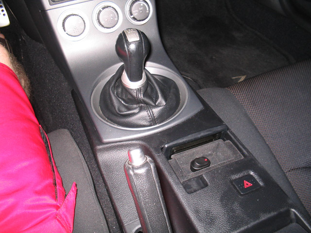
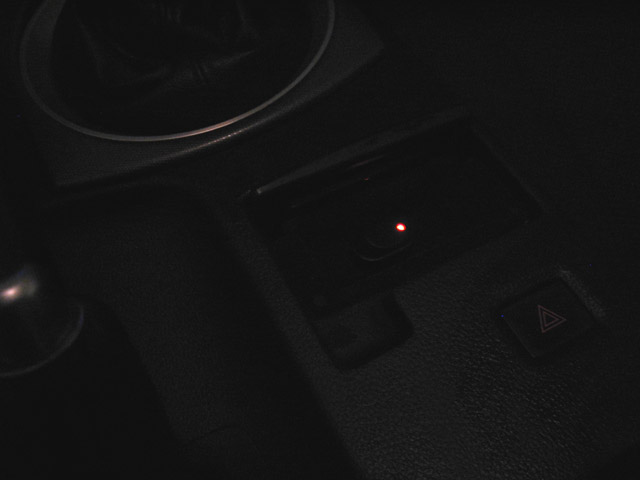
All you've got to do is wire in a switch to the orange wire that plugs into the bosch unit in the center console. Then install the switch in the bottom of the coil tray and it stays perfectly hidden. I did this mod and it took a total of 15 minutes including the time spent soldering the splices and using heat shrink to seal them up right.
Last edited by taurran; 05-26-2006 at 04:22 AM.
05-26-2006, 05:11 AM
#27
Registered User
iTrader: (56)
Join Date: Jun 2005
Location: Miami
Posts: 1,894
Likes: 0
Received 0 Likes
on
0 Posts
Thanks taurran but the problem is i dont want to be cutting wires in the car. The only thing holding me back is that freaking fuse that i dont know how to drill it.
If someone would just tell me in detail i could finish it right away i have all the wires connected already.
If someone would just tell me in detail i could finish it right away i have all the wires connected already.
05-26-2006, 09:26 AM
#29
Registered User
Thread Starter
iTrader: (24)
Join Date: Aug 2005
Location: NewCastle, WA
Posts: 2,947
Likes: 0
Received 0 Likes
on
0 Posts
<---X - Fuse - X
l
X - Fuse - X
l l
l l
Sorroy for the poor 'drawing', but this is how the 'add a circuit' coponent looks...the X's are the holes where the fuses would normaly plug into. TGhe top left X is where the 'power' wire comes from. This is how it should look after modifing it:
<---X - Fuse - X
l
<---X -empty- X
l l
l l
*you leave the bottom fuse empty, and add the extra wire to the bottom left position. I used a soldering iron to melt that part of the plastic away and then soldered the wiring in place - I then wraped each wire with electrical tape to secure it.
I only used a drill when installing the switch.
hope that helps!
l
X - Fuse - X
l l
l l
Sorroy for the poor 'drawing', but this is how the 'add a circuit' coponent looks...the X's are the holes where the fuses would normaly plug into. TGhe top left X is where the 'power' wire comes from. This is how it should look after modifing it:
<---X - Fuse - X
l
<---X -empty- X
l l
l l
*you leave the bottom fuse empty, and add the extra wire to the bottom left position. I used a soldering iron to melt that part of the plastic away and then soldered the wiring in place - I then wraped each wire with electrical tape to secure it.
I only used a drill when installing the switch.
hope that helps!

 05-27-2006, 07:46 AM
#34
Registered User
iTrader: (25)
Join Date: Jan 2006
Location: Phoenix
Posts: 784
Likes: 0
Received 0 Likes
on
0 Posts
If you look up at the top arm on the brake petal you will see a small pin switch that goes to that switch. You should be able to just cut it and add a switch to the power side of it and leave the fuse as-is.
05-27-2006, 07:49 AM
#35
Registered User
iTrader: (18)
Join Date: Oct 2004
Location: .
Posts: 9,482
Likes: 0
Received 0 Likes
on
0 Posts
Yeah, I really don't understand why you're going through the trouble of doing this at a fuse level. Splicing into a wire is so much easier, and more reversible , than drilling into anything. If you want to try my method, I can give you more details on the wire in question, but its up to you.
 09-04-2019, 10:08 PM
#38
Registered User

Join Date: Sep 2019
Location: United states
Posts: 1
Likes: 0
Received 0 Likes
on
0 Posts
ok i found the thread with the pics now i know what to do but i just dont know how the hell am i goig to drill that fuse help on the drilling part any tips ideas. I tried shaving the head down so i could get more metal but that plastic is hard. Anyother way to get to it.
https://my350z.com/forum/showthread.php?t=144005
https://my350z.com/forum/showthread.php?t=144005


Thread
Thread Starter
Forum
Replies
Last Post