
DIY plenum porting
 08-30-2006, 05:48 PM
#301

WHAT ARE YOU THINKING!!
Dont let anyone know what you did. Then they will be able to do it them selves. How are you suppose to make ANY money

Later
Aceman
Dont let anyone know what you did. Then they will be able to do it them selves. How are you suppose to make ANY money
Later
Aceman
Originally Posted by Audible Mayhem
hopefully i will be purchasing a AWD dynojet in the next couple weeks. *fingers crossed* i will be doing all kinda top secret porting and polishing, i will let everyone know what i do when i do it and if anyone in the orlando area wants to try some stuff out, let me know!!
more updates on the upgraded MAF as well....
more updates on the upgraded MAF as well....
 10-09-2006, 03:07 AM
#302
Registered User
iTrader: (8)

Join Date: Feb 2006
Location: ATL
Posts: 589
Likes: 0
Received 0 Likes
on
0 Posts
Okay, finally got mine on. However, there are couple factors.
1. I had the pre-dyno, but from Sharif's shop. The after dyno will be at another shop, so it's not consistant.
2. The machine job on the plenums are mild as I didn't want to mess with the Original MREV2 much.
3. Headers are also installed so there's no control test.
However, I'll do some other dynos and will start working on the removed plenums and see if I can over come that power. There are more things to be added.
Will try to dyno sometimes this week.
 11-21-2006, 09:24 AM
#304
Registered User
iTrader: (24)
Join Date: Aug 2005
Location: NewCastle, WA
Posts: 2,947
Likes: 0
Received 0 Likes
on
0 Posts
thought I'd add a few photos of what I've been working on - I've shaved down all the tops on each runner (a lot more on the 2 fronts), and have begun polishing alot of the interior...I won't polish it to a mirror finish, but will leave it somewhat rough.
I used my router, some random peices of wood, a level and some clamps to make the cuts...all of the cuts turned out straight and at the depth I wanted (I would have loved to do this on a mill, but don't have access to one or the $$ to buy one)
**I'm currently finishing it, rounding all of the edges and making it smooth!


Once I finish, I'll post the end results. (I'll be getting a dyno in the next few months, but won't be able to do before/After...I'm getting ready for an AAM reflash and don't have too much extra $$ laying around for more dynos)
-Peter
I used my router, some random peices of wood, a level and some clamps to make the cuts...all of the cuts turned out straight and at the depth I wanted (I would have loved to do this on a mill, but don't have access to one or the $$ to buy one)
**I'm currently finishing it, rounding all of the edges and making it smooth!
Once I finish, I'll post the end results. (I'll be getting a dyno in the next few months, but won't be able to do before/After...I'm getting ready for an AAM reflash and don't have too much extra $$ laying around for more dynos)
-Peter
11-21-2006, 08:20 PM
#305

I may be really out of place here but I am in the tool and mold industry I really think you should be using a carbide cutter on that intake to take down that material. Also it would be nice if you were using a nice dumor with a flex shaft to get into some of the tougher places.
But besides that has any one ever put one of these intakes on a flow bench to see what is going on. You could hog the crap out of it and then just use some clay to build up areas that may need work and check the the numbers as you go along. Also has anyone ever flowed the heads and maybe looked at doing a port and polish on them or maybe get a few sets and try some stuff on the flow bench. I am not really an expert on this stuff but once you got some numbers off the flow bench and were able to chart some changes you could easily set up a job and start cnc ing those heads. I would think you could find alittle power in the heads.. Have people ever gone the trouble of putting larger valves and stuff in???? Like I said I dont really know alot about this stuff but wouldnt you easily find 15 -20 hp in the heads atleast with a good cnc jobb???? I really think that the intake would be good for about the same too.. But I think that has been proven..
This stuff is pretty cool though
THANX
11-24-2006, 06:17 AM
#307
Registered User
iTrader: (1)

Join Date: Aug 2006
Location: Ontario, Canada
Posts: 4
Likes: 0
Received 0 Likes
on
0 Posts
Originally Posted by striker27
But besides that has any one ever put one of these intakes on a flow bench to see what is going on. You could hog the crap out of it and then just use some clay to build up areas that may need work and check the the numbers as you go along.
Flow benches DO NOT work well for IM work because they do not simulate the opening and closing of intake valves and their effect on the momentum of the air and the interaction with other cylinders.
Any IM on a flow bench would yield the best numbers with 0 runner length and just a big bellmouth. This would be awesome for extreme rpm power but your low to midrange torque would suck.
I have my own little DIY IM project going on. I am using a simple inclined manometer to try and balance the pressure drops for all cylinders for a given flow without significantly altering the runner lengths.
Last edited by eng92; 11-24-2006 at 06:25 AM.
11-25-2006, 07:42 PM
#308
Registered User
iTrader: (24)
Join Date: Aug 2005
Location: NewCastle, WA
Posts: 2,947
Likes: 0
Received 0 Likes
on
0 Posts
you're probably right about the carbide cutter, but I didn't have one and after trying it out, the cutter held up fine - I went slow, to lessen the stress. At some point I should also get a flex shaft, but haven't had time to it yet...know of any good places I could get them from?
thanks,
Peter
thanks,
Peter
Originally Posted by striker27
I may be really out of place here but I am in the tool and mold industry I really think you should be using a carbide cutter on that intake to take down that material. Also it would be nice if you were using a nice dumor with a flex shaft to get into some of the tougher places.
But besides that has any one ever put one of these intakes on a flow bench to see what is going on. You could hog the crap out of it and then just use some clay to build up areas that may need work and check the the numbers as you go along. Also has anyone ever flowed the heads and maybe looked at doing a port and polish on them or maybe get a few sets and try some stuff on the flow bench. I am not really an expert on this stuff but once you got some numbers off the flow bench and were able to chart some changes you could easily set up a job and start cnc ing those heads. I would think you could find alittle power in the heads.. Have people ever gone the trouble of putting larger valves and stuff in???? Like I said I dont really know alot about this stuff but wouldnt you easily find 15 -20 hp in the heads atleast with a good cnc jobb???? I really think that the intake would be good for about the same too.. But I think that has been proven..
This stuff is pretty cool though
THANX
But besides that has any one ever put one of these intakes on a flow bench to see what is going on. You could hog the crap out of it and then just use some clay to build up areas that may need work and check the the numbers as you go along. Also has anyone ever flowed the heads and maybe looked at doing a port and polish on them or maybe get a few sets and try some stuff on the flow bench. I am not really an expert on this stuff but once you got some numbers off the flow bench and were able to chart some changes you could easily set up a job and start cnc ing those heads. I would think you could find alittle power in the heads.. Have people ever gone the trouble of putting larger valves and stuff in???? Like I said I dont really know alot about this stuff but wouldnt you easily find 15 -20 hp in the heads atleast with a good cnc jobb???? I really think that the intake would be good for about the same too.. But I think that has been proven..
This stuff is pretty cool though
THANX
11-27-2006, 11:34 AM
#309
Registered User

Join Date: Sep 2006
Location: denver
Posts: 637
Likes: 0
Received 0 Likes
on
0 Posts
We always have to remember that anymore, unlike the olden days of hot roding, that performance cars are very engineered using large teams of engineers who know what they are doing, and do what they do based on trade offs... cost, performance, reliability, manufacturing constraints, etc. So anything we do will most likely not do much better than them... to me it's amazing anymore that you can gain something like 13 hp off an mrev2... I think 3-4 HP is a decent gain.... lets give the engineers some credit, right?
I will say, that this really reminds of me waveguide.... I'm an electrical engineer, and talking about presure waves, combined with laminar flow, etc, though slightly different, is VERY similar to waveguide.... (a waveguide is a metal tube that you design to carry elecromagnetic fields, rather than doing it in a wire like you usually do, or just broadcasting it through the air like in radio). In EM there are different "modes" of propigation, each can be effected very much so by the shape, length, etc of the tude, surprisingly, as the above articles have shown, the diameter of the waveguide does not make a large difference in it's design, only the over all power it can handle.
In any case... based on what I've read through this thread, and what I know of resonant waveguide cavities (similar to these plenums) I'd say that the best way to "impedance match" (which is what you're trying to do, only for pressure) for more than just 1 frequency (runner length) is to cut slits in the runners, which would allow the runner to change it's "length" based on the distance the slits are apart from eachother, and any wavelength (dependant on frequency, which is dependant on valve timing and rpm, etc) that does not fit into the length of one of the slits will go into a strange mode, but wont loose too much power. Problem with this is... we dont have to deal with lamenar flow in EM, but we do deal with the fact that the energy of the EM field couples to the metal of the wavequide, which causes a current in it, which determines many of the characteristics of the propigation.... which is similar to laminar flow, but not the same... so I dont know how it would effect laminar flow, but looking at it from an EM standpoint, it would work.
Also, increasing the angle of attack into the runners (as was done above for the 3-4 hp gain) will increase the band width of the impedance match of the runner to the camber, which might be why you saw the gain, and why milling out the bottom infront of the runners might also help... at least it seems to my thought....
just my 2 cents...
11-30-2006, 07:55 PM
#310
Registered User
iTrader: (24)
Join Date: Aug 2005
Location: NewCastle, WA
Posts: 2,947
Likes: 0
Received 0 Likes
on
0 Posts
i finnaly got around to polishing and smoothing out the surfaces on the lower plenum. i also removed the lower collector, smoothed out the casting lines, port matched it to the lower plenum and re-installed it with MD's iso-themral gasket. I painted the lower plenum with high temp ceramic paint outside and in - I did this for 2 reason, 1st - it should act as a thermal barrier, hopefully reducing the heat transfer to the air flow, 2nd, internally i hope that it'll further smooth out the surfaces and create a more consistent surface for the air to flow over.
I had also finished the upper plenum, but when I put it in the oven to help set the paint, the top portion (in direct sight of the oven heater rods) began to bubble...I'm not exactly sure why it did this, I've done this process before and never had any problems; I'm currently redoing the entire upper plenum exterior. (When I had baked components with high temp before, the paint would have a much tougher exterior and would be much less prone to scuffing/scratches).
I'll be adding AAM's angled plenum spacer and intake in the next few weeks to round out my intake system...now I just have to find a day where it's not raining or snowing!


lower plenum w/ taping to prevent paint in unwanted areas

upper plenum just before baking

the TB, I slightly grinded it to match it to the upper plenum


**I just took it out tonight, roads were still a little wet, so I didn't push it too hard. But the general feel is that the higher RPM HP/TQ is stronger and feels like it has more only if I had a higher RPM limit (good thing I'll be getting AAM's reflash )
)
-Peter
I had also finished the upper plenum, but when I put it in the oven to help set the paint, the top portion (in direct sight of the oven heater rods) began to bubble...I'm not exactly sure why it did this, I've done this process before and never had any problems; I'm currently redoing the entire upper plenum exterior. (When I had baked components with high temp before, the paint would have a much tougher exterior and would be much less prone to scuffing/scratches).
I'll be adding AAM's angled plenum spacer and intake in the next few weeks to round out my intake system...now I just have to find a day where it's not raining or snowing!
lower plenum w/ taping to prevent paint in unwanted areas
upper plenum just before baking
the TB, I slightly grinded it to match it to the upper plenum
**I just took it out tonight, roads were still a little wet, so I didn't push it too hard. But the general feel is that the higher RPM HP/TQ is stronger and feels like it has more only if I had a higher RPM limit (good thing I'll be getting AAM's reflash
)-Peter
Last edited by first350; 11-30-2006 at 08:04 PM.
 12-01-2006, 10:45 AM
#312
Registered User
iTrader: (24)
Join Date: Aug 2005
Location: NewCastle, WA
Posts: 2,947
Likes: 0
Received 0 Likes
on
0 Posts
Originally Posted by shavel
That's alot of work! Nice job! will you dyno it before the flash?
I'll dyno before I get the AAM flash, but I'll have added Strup headers, AAM y-pipe and full 3" single Ti exhaust, UR flyhweel/clutch and probably some other stuff that I'm forgetting...
-Peter
12-01-2006, 06:14 PM
#313
First350,
Before driving any more I would do a "hot motor oil" compatibility check of the paint used inside the plenum assembly.
Make sure the dried paint isn't soluable in hot motor oil. There can be a lot of oil vapors condensing in there. Enough to be substantial. It varies from car to car, but its no small amount.
Tony
BTW Good job on the milling!
12-01-2006, 07:01 PM
#314

just an idea,
I know Cosworth on the race car engines they make, they actually cut grooves into the runners. like straight lines following the direction of the airflow. all the same size and same space apart.
and they also say a mirror finish is not good. it creates some sort of air resonance or something. I guess that is the turbulence you guys talked about.
I have he 1/2 spacer I think I will pull it all apart and jsut clean everything up, I don't want to alter anything unless I see something that needs to be removed. I think just by making sure all the parts have the same port size (like the tb to plenum neck, lower to mid, mid to upper) and no casting marks.
you guys did great, with the larger MAF and intake tube stuff this is all great!
I ported my TB so I figured I could clean up everything else!
12-03-2006, 12:47 PM
#315
Registered User
iTrader: (24)
Join Date: Aug 2005
Location: NewCastle, WA
Posts: 2,947
Likes: 0
Received 0 Likes
on
0 Posts
Originally Posted by Hydrazine
First350,
Before driving any more I would do a "hot motor oil" compatibility check of the paint used inside the plenum assembly.
Make sure the dried paint isn't soluable in hot motor oil. There can be a lot of oil vapors condensing in there. Enough to be substantial. It varies from car to car, but its no small amount.
Tony
BTW Good job on the milling!
Before driving any more I would do a "hot motor oil" compatibility check of the paint used inside the plenum assembly.
Make sure the dried paint isn't soluable in hot motor oil. There can be a lot of oil vapors condensing in there. Enough to be substantial. It varies from car to car, but its no small amount.
Tony
BTW Good job on the milling!
good point Hydrazine - it's supposed to be resistant to oils, but I should just double check - the only thing they said to worry about was direct flame contact. (When i took off my OE plenum, there was a good amount of oil in it).
-Peter
12-04-2006, 09:13 AM
#316
Registered User
Join Date: Sep 2006
Location: denver
Posts: 637
Likes: 0
Received 0 Likes
on
0 Posts
Originally Posted by Motormouth
just an idea,
I know Cosworth on the race car engines they make, they actually cut grooves into the runners. like straight lines following the direction of the airflow. all the same size and same space apart.
and they also say a mirror finish is not good. it creates some sort of air resonance or something. I guess that is the turbulence you guys talked about.
I have he 1/2 spacer I think I will pull it all apart and jsut clean everything up, I don't want to alter anything unless I see something that needs to be removed. I think just by making sure all the parts have the same port size (like the tb to plenum neck, lower to mid, mid to upper) and no casting marks.
you guys did great, with the larger MAF and intake tube stuff this is all great!
I ported my TB so I figured I could clean up everything else!
I know Cosworth on the race car engines they make, they actually cut grooves into the runners. like straight lines following the direction of the airflow. all the same size and same space apart.
and they also say a mirror finish is not good. it creates some sort of air resonance or something. I guess that is the turbulence you guys talked about.
I have he 1/2 spacer I think I will pull it all apart and jsut clean everything up, I don't want to alter anything unless I see something that needs to be removed. I think just by making sure all the parts have the same port size (like the tb to plenum neck, lower to mid, mid to upper) and no casting marks.
you guys did great, with the larger MAF and intake tube stuff this is all great!
I ported my TB so I figured I could clean up everything else!
Sweet! they took my idea to heart! lol... And the mirror finish thing.. it was covered in a post earlier from wiki... when a not smooth finish the laminar flow is stoped, so there is a small laryer of air that pretty much doesnt move that is in contact with the metal, which the rest of the air then flows in, like a cylender of of air, for air to flow through. With a mirror smooth finish this layer has a harder time forming, and you get more laminar flow, effectively reducing the overall flow of air, or so was my understanding from the wiki article (similar to skin effect in elecromagnetics). But if there is a large jut into the air flow, then that is bad... but having a slightly ruff surface is actually better...
Last edited by shushikiary; 12-04-2006 at 09:17 AM.
12-05-2006, 07:33 AM
#317
Registered User
iTrader: (24)
Join Date: Aug 2005
Location: NewCastle, WA
Posts: 2,947
Likes: 0
Received 0 Likes
on
0 Posts
What do you guys think about cutting off the 6 interior posts that carry the 6 bolts...what do they really help to do? Doesn't seem like they'd help much to seal the plenum...

-Peter
-Peter
Last edited by first350; 12-05-2006 at 07:36 AM.
12-05-2006, 11:05 AM
#318
Originally Posted by first350
What do you guys think about cutting off the 6 interior posts that carry the 6 bolts...what do they really help to do? Doesn't seem like they'd help much to seal the plenum...
-Peter
-Peter
12-05-2006, 06:28 PM
#319
I wouldnt recommend cutting them out. 2 reasons.
1) The air velocity in that area is much too low for there to be an obstruction, so there arent any gains to be made.
2) With that said, there is no reason to reduce the structural support.
Sealing should be easy with or without them but with nothing to gain, I wouldn't recommend it.
1) The air velocity in that area is much too low for there to be an obstruction, so there arent any gains to be made.
2) With that said, there is no reason to reduce the structural support.
Sealing should be easy with or without them but with nothing to gain, I wouldn't recommend it.
01-16-2007, 07:24 PM
#320
After reading these two posts below I was observing that runners 1, 2, 5, 6 are all longer than runners 3 and 4. Maybe the angle cutting isn't a bad idea on those fours longer runners to make them the same length as runners 3 and 4. I now have an extra manifold (the 3 pieces) and are ready to go to work...what's your input?
Originally Posted by bilinghm
O.K. here is my idea for an improved plenum. I would do all of the previously discussed modifications, plus I would change the angle of the mouth of each runner. I would �lay back� the bell mouth between 5 and 10 degrees (85 to 80) instead of the current 90 degree angle. The shaded area in the photo would be milled off, with the ports ground and blended.
Originally Posted by aceman
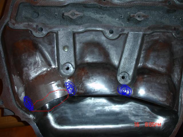
If you look at this pic you can see what i ported on the plenum. The red area, i removed half a inch off of the front of the front two ports and a half a inch off of the top of the same two ports. Plus i ported the inside out.
The blue area i opened up quiet a bit so that air could move into the bowl area more freely.
The center two ports i opened up just alittle to alow a velocity stack effect.
The back to ports i just smoothed out.
Going to finish polishing it up tonight and post more pics.
Later
Aceman
The blue area i opened up quiet a bit so that air could move into the bowl area more freely.
The center two ports i opened up just alittle to alow a velocity stack effect.
The back to ports i just smoothed out.
Going to finish polishing it up tonight and post more pics.
Later
Aceman