
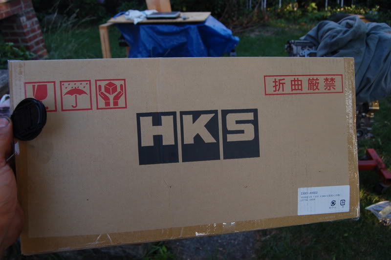
Assembly of my new Built Short Block

So far,most of you have noticed my removing of my stock engine and tranny (see other thread). In addition, I opened a thread describing the breakdown of the motor to the core. Now comes the interesting part...Where I attempt to assemble my new engine starting from a built short block purchased from Kyle at Import Parts Pro.
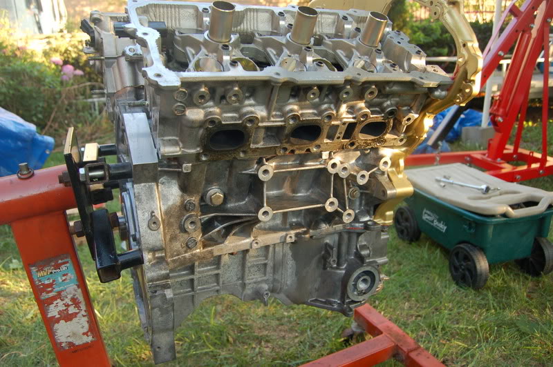
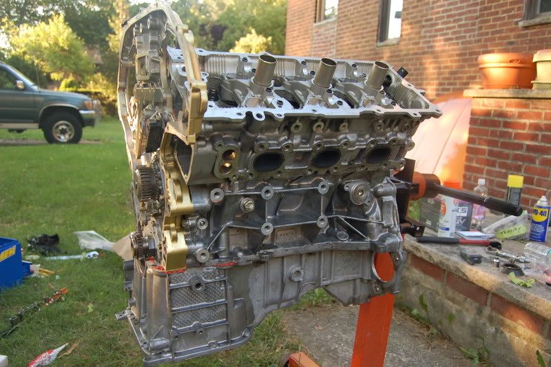
I started off really simple, performing the reverse of the last few things I performed in the breakdown. Namely I attached the upper oil pan, and proceeded to prep the head gasket and place the heads back down. Yes, the heads were machined for a precise fit to the new block.
I sprayed Copper spray which is a sort of elastic spray with a copper element which adds an extra layer of protection and seal to the already amazing HKS head gasket. It also colors copper so you know when you have covered the surface area appropriately.
Unfortunately my camera battery died when I started the rebuild so I didn't capture the copper painted gasket...No big deal. Just spray the gasket, both sides, lay it down and place the heads down on top of it. Nor did I capture the upper oil pan install. No biggie either.
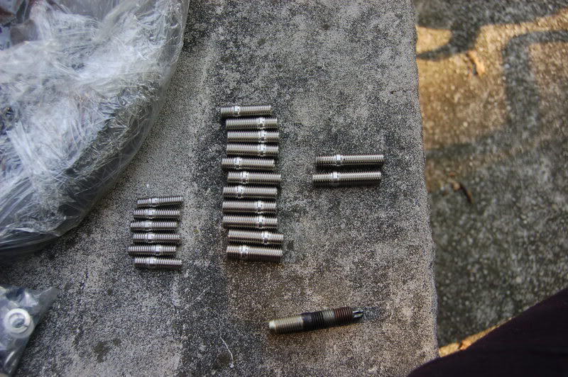
ARP L19 Head Studs dropped in place:
Heads are now in place and torqued to a total 92 ft/lbs in proper sequence and in stages of torque.
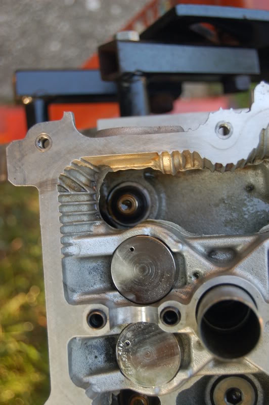
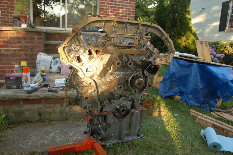
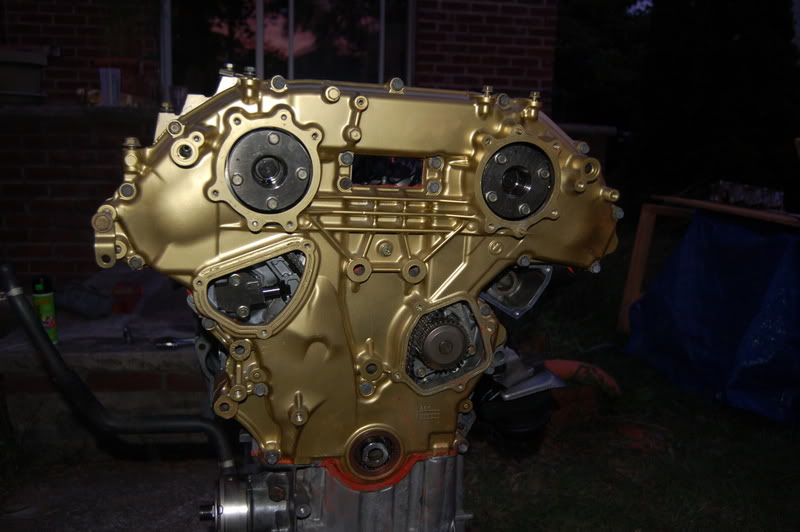
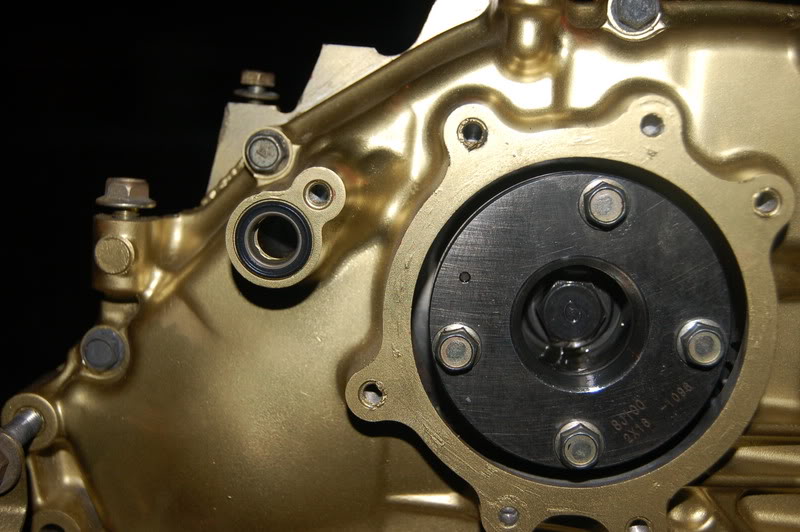
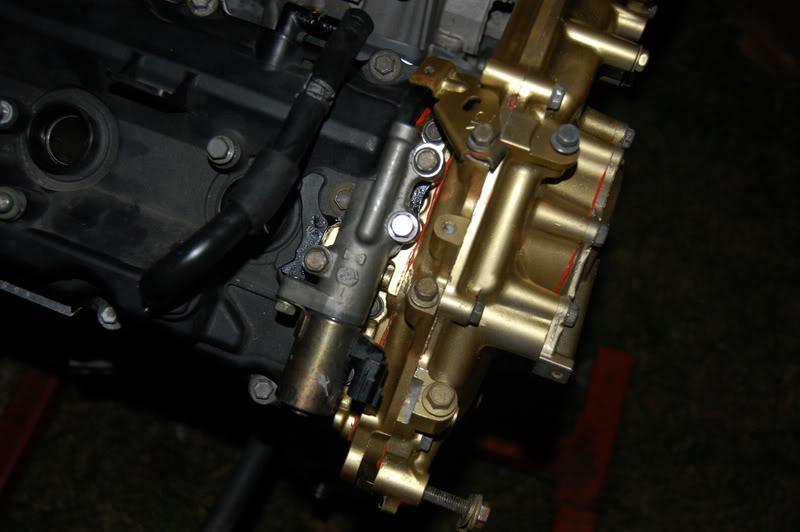
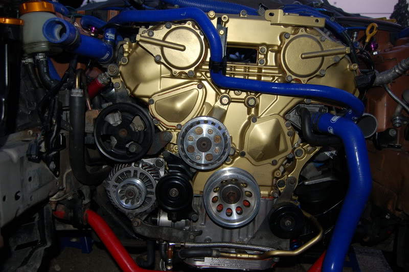
Here we go with the rearward timing cover which I painted gold, so the front of the engine will look like it is made of gold.
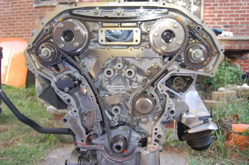
You will see that the cams must be put in place here. They are set up in any position that is comfortable and allows them to be fastened down. They can always be turned once secured. The caps that hold down the cams must be done in a sequence identified in the manual and to specific torque patterns.
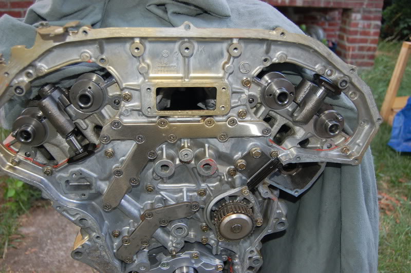
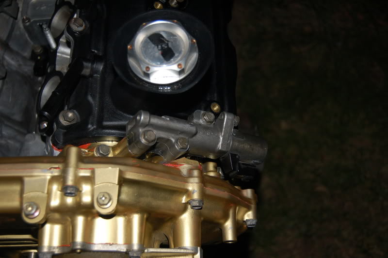
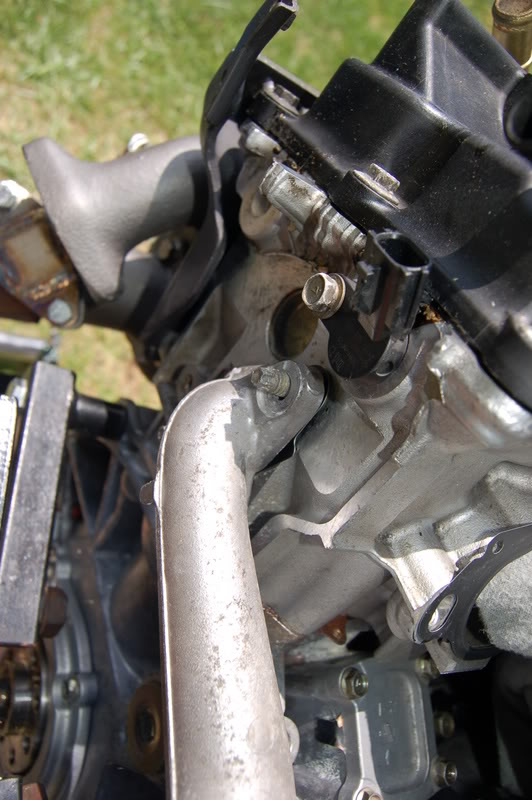
Cam Sensor put back in position both sides.
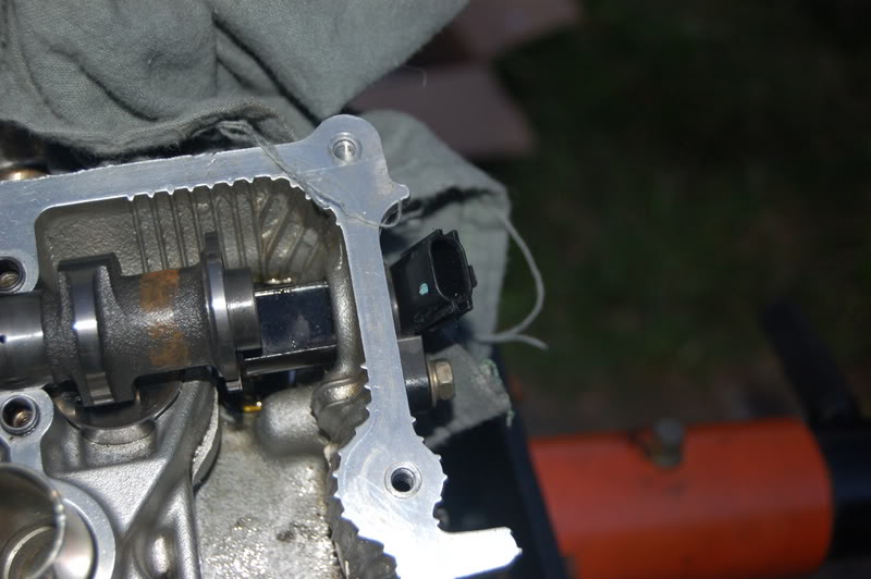
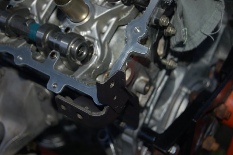
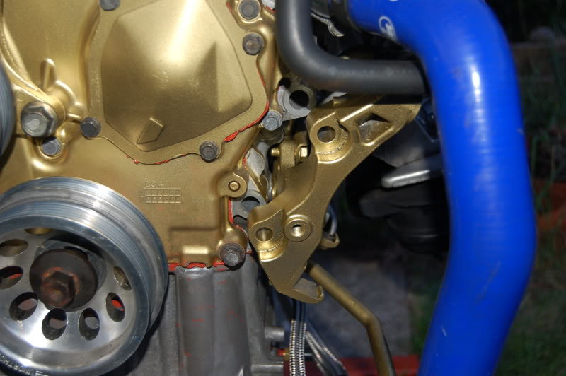
As well as the corner bracket:
It is important to have both torque wrenches...One for ft/lbs and one for inch/lbs that can count very low...as low as 17 inch/lbs (for some of the smaller bolts).
Once the cams are secured down, they must be aligned to 180 degrees, meaning that the marks at the ends of the lines line up vertically.
Next the cams gears can be mounted at the ends of the cams. I found it to be much easier to have someone help when torquing the gear heads on to the cams. You do go to I think 85ft/lbs of torque for these cam gear heads...
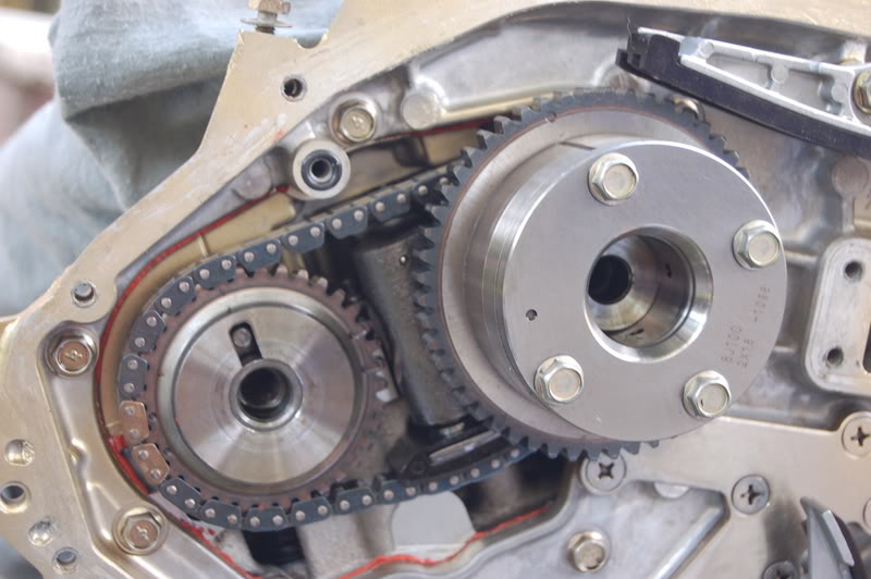
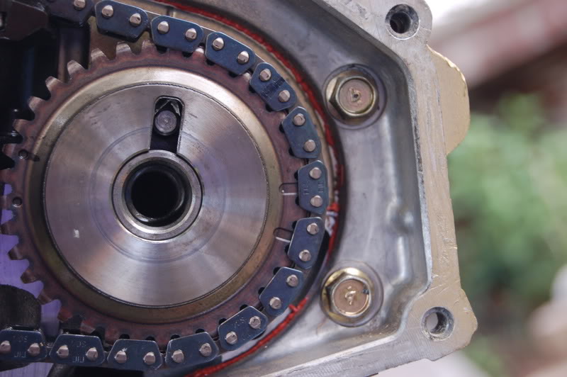
Moving along, once the cam chain and gear heads are in place, just make sure the marks are matching. On the left you match up the chain to circle marks, and on the right you make to the oval marks, I think I've got both pictured.
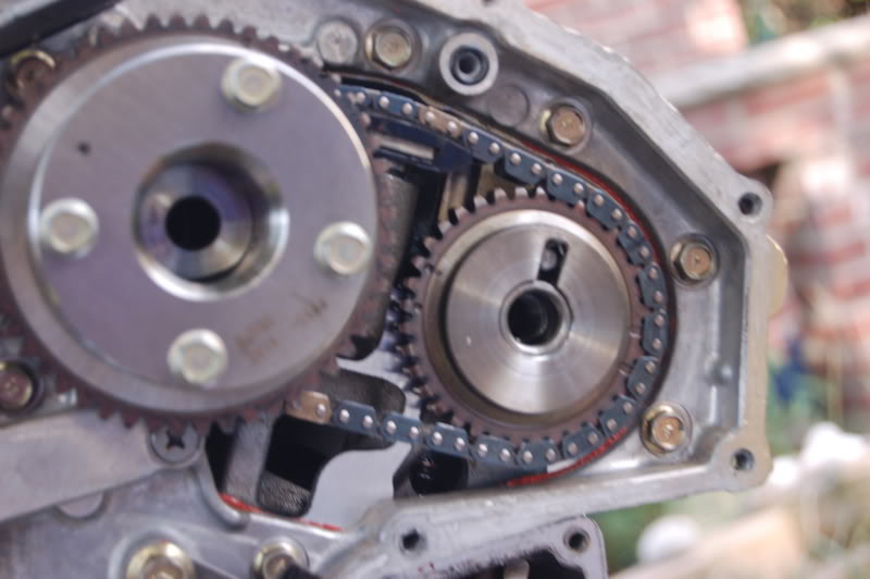
Once the cam chains (smaller ones are good, you can place the larger cam chain over the front making a bit of a Y shape. You will need to install the tensioners and make sure that they are all still in good shape. Take a good look at the timing chain...this may be a good time to replace it. Inspect every link for cracks or any damage at all. Mine looked good, so I decided to re-use.
Once all of the tensioners are in place the timing cover goes back on.
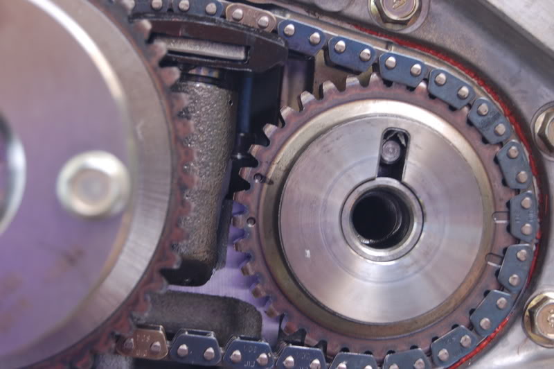
The chain once installed appeared to have a lot of slack, but once the tensioner on the left was put back in, it all tightened up. Great.
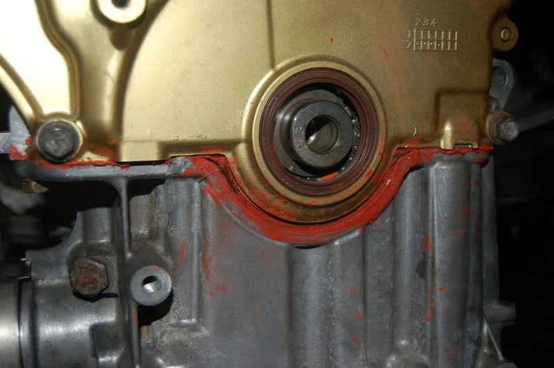
Careful with the gasket at the bottom of the front of the timing cover, it didn't want to cooperate at first.
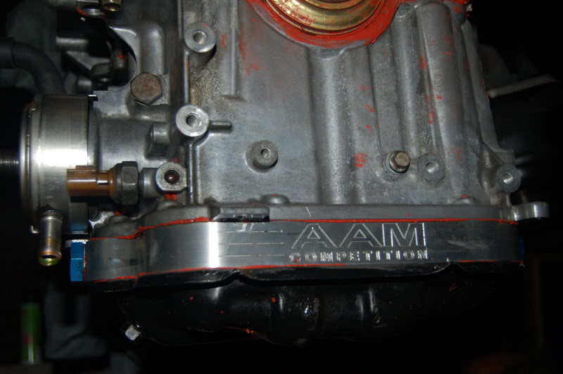
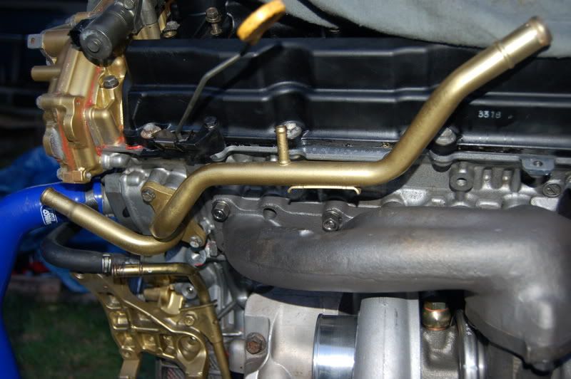
Oil Pan with spacer for my turbo oil return lines.
These timing cam covers have a small washer gasket that must be replaced before you put the cap back on, as well you must use RTV on each of the 4 front covers.
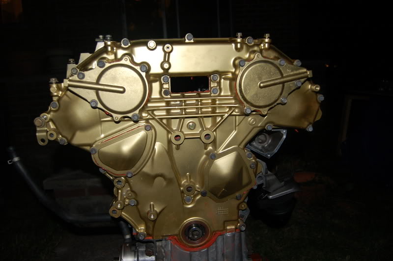
The new cover in gold looks sweet:
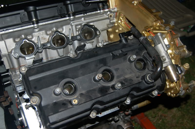
Even with night time arriving and the mosquitoes biting I persisted and put on the valve covers with new gaskets of course.
NOTE*** Before putting on the valve covers it was advised to put a quart of oil over the cams on both sides to help in spreading the oil on the vital engine parts to aid in starting for the first time.
I realize that much of it will probably settle to the bottom before I start it, so I will hold off on adding more, until I am ready to fill all of the other fluids.
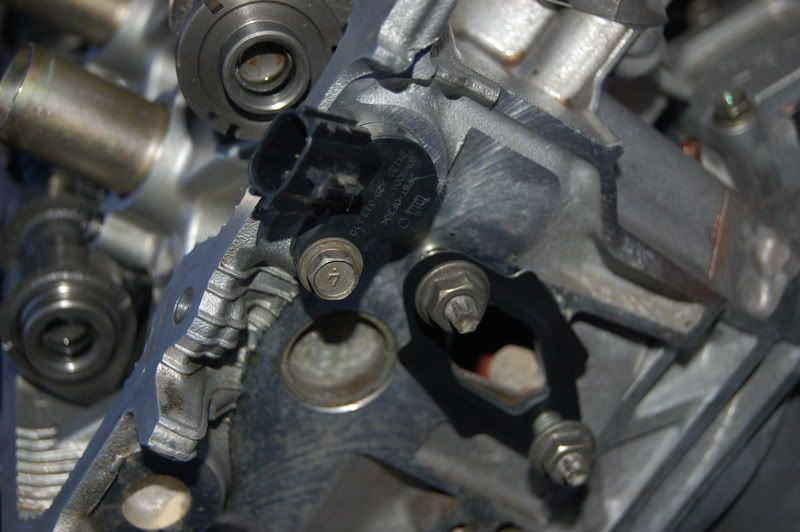
Then I put back the check valves..both sides down to proper torque spec.
Once we checked everything by turning the engine over a few times by spinning the crank using a ratchet. The engine has no oil, so it took a little of elbow grease. It felt good to turn the engine over. Very tough, but that is to be expected. Nice tight compression. You can feel it stroke through as it turns.
Moving along pretty smoothly, thanks to the help of my mechanic friend who was overseeing this part of the install.
More to follow.
I started off really simple, performing the reverse of the last few things I performed in the breakdown. Namely I attached the upper oil pan, and proceeded to prep the head gasket and place the heads back down. Yes, the heads were machined for a precise fit to the new block.
I sprayed Copper spray which is a sort of elastic spray with a copper element which adds an extra layer of protection and seal to the already amazing HKS head gasket. It also colors copper so you know when you have covered the surface area appropriately.
Unfortunately my camera battery died when I started the rebuild so I didn't capture the copper painted gasket...No big deal. Just spray the gasket, both sides, lay it down and place the heads down on top of it. Nor did I capture the upper oil pan install. No biggie either.
ARP L19 Head Studs dropped in place:
Heads are now in place and torqued to a total 92 ft/lbs in proper sequence and in stages of torque.
Here we go with the rearward timing cover which I painted gold, so the front of the engine will look like it is made of gold.
You will see that the cams must be put in place here. They are set up in any position that is comfortable and allows them to be fastened down. They can always be turned once secured. The caps that hold down the cams must be done in a sequence identified in the manual and to specific torque patterns.
Cam Sensor put back in position both sides.
As well as the corner bracket:
It is important to have both torque wrenches...One for ft/lbs and one for inch/lbs that can count very low...as low as 17 inch/lbs (for some of the smaller bolts).
Once the cams are secured down, they must be aligned to 180 degrees, meaning that the marks at the ends of the lines line up vertically.
Next the cams gears can be mounted at the ends of the cams. I found it to be much easier to have someone help when torquing the gear heads on to the cams. You do go to I think 85ft/lbs of torque for these cam gear heads...
Moving along, once the cam chain and gear heads are in place, just make sure the marks are matching. On the left you match up the chain to circle marks, and on the right you make to the oval marks, I think I've got both pictured.
Once the cam chains (smaller ones are good, you can place the larger cam chain over the front making a bit of a Y shape. You will need to install the tensioners and make sure that they are all still in good shape. Take a good look at the timing chain...this may be a good time to replace it. Inspect every link for cracks or any damage at all. Mine looked good, so I decided to re-use.
Once all of the tensioners are in place the timing cover goes back on.
The chain once installed appeared to have a lot of slack, but once the tensioner on the left was put back in, it all tightened up. Great.
Careful with the gasket at the bottom of the front of the timing cover, it didn't want to cooperate at first.
Oil Pan with spacer for my turbo oil return lines.
These timing cam covers have a small washer gasket that must be replaced before you put the cap back on, as well you must use RTV on each of the 4 front covers.
The new cover in gold looks sweet:
Even with night time arriving and the mosquitoes biting I persisted and put on the valve covers with new gaskets of course.
NOTE*** Before putting on the valve covers it was advised to put a quart of oil over the cams on both sides to help in spreading the oil on the vital engine parts to aid in starting for the first time.
I realize that much of it will probably settle to the bottom before I start it, so I will hold off on adding more, until I am ready to fill all of the other fluids.
Then I put back the check valves..both sides down to proper torque spec.
Once we checked everything by turning the engine over a few times by spinning the crank using a ratchet. The engine has no oil, so it took a little of elbow grease. It felt good to turn the engine over. Very tough, but that is to be expected. Nice tight compression. You can feel it stroke through as it turns.
Moving along pretty smoothly, thanks to the help of my mechanic friend who was overseeing this part of the install.
More to follow.
Last edited by rrmedicx; Jul 22, 2007 at 08:00 PM.
Thanks for the props. I am trying to get this thing together as efficiently and effectively as I can. Checking the manual so I only have to do this once.
I got stuck re-torquing the heads first to 85, then after getting some good advice on this forum, I removed the nuts added plenty of moly lube and replaced the nuts, torquing them down to 92ft/lbs each. (Not the 85ft/lbs ARP stated)
I got stuck re-torquing the heads first to 85, then after getting some good advice on this forum, I removed the nuts added plenty of moly lube and replaced the nuts, torquing them down to 92ft/lbs each. (Not the 85ft/lbs ARP stated)
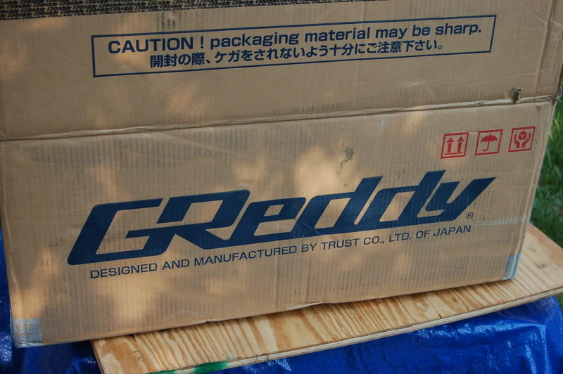
Parts on order:
Greddy TT (Recv'd)
Greddy TT exhaust (pending)
OS Giken Twin Clutch (pending)
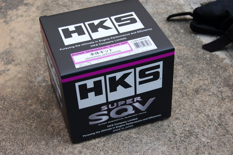
HKS BOV (recv'd)
Replacement tranny - on hand CD009
Hopefully to arrive this week to help complete the install.
Greddy TT (Recv'd)
Greddy TT exhaust (pending)
OS Giken Twin Clutch (pending)
HKS BOV (recv'd)
Replacement tranny - on hand CD009
Hopefully to arrive this week to help complete the install.
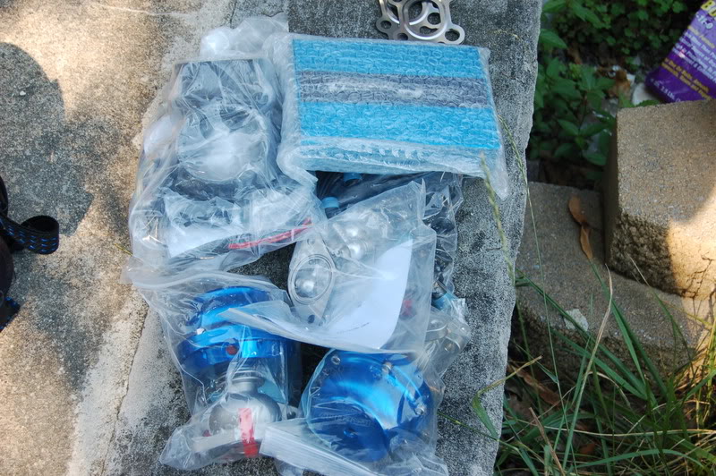
Here are some parts I'll be adding:
Some stuff I won't be needing:
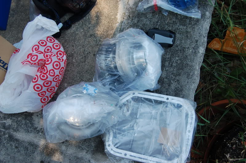
Won't need this...I have my UTEC:
The kit comes pretty complete...with theexception of a BOV )(Blow off Valve), gaskets are also included.
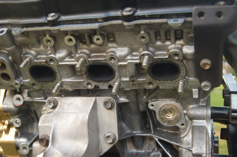
Some of the studs:
They actually want you to remove the stock ones and go to the Greddy ones instead. Strange, because they are shorter than stock, but I guess they are stronger.
It helps to assemble each side, with hoses and gaskets:
Then its just a mater of putting on the nuts to hold it up.
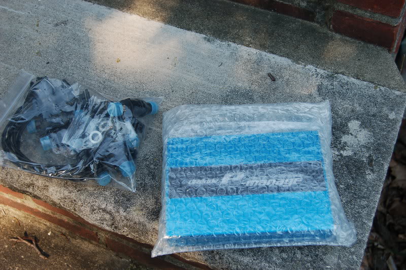
I bought Stainless Steel Return lines for the security and added bling factor:
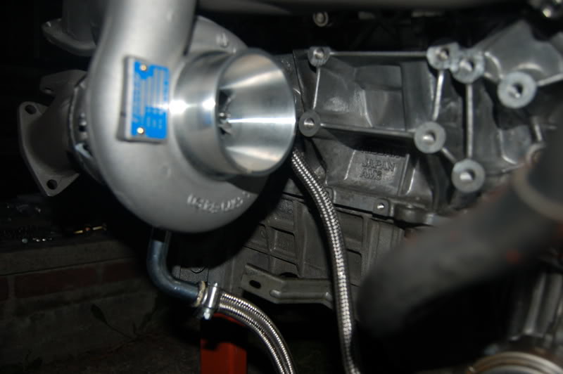
Here is what you have to do to get oil to the turbos:
Flip-side:
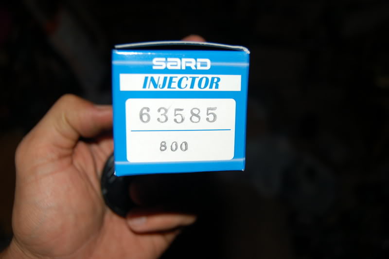
Injectors 800cc SARD...Top of the line. These are high impedance injectors.
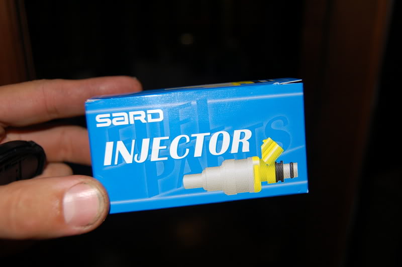
I read that you can use a little oil to help inserting them into the fuel rail easier. Otherwise it would be ridiculously tight and you would risk damaging the O-rings at the top of each injector. One damaged O-ring could lead to a whole lot of problems...Burning probems...

Set up the new radiator, putting the old A/C condensor in front of it.
A little more GOLD:
Brackets too:
Water Pump:
That's all for now. More Friday.
Some stuff I won't be needing:
Won't need this...I have my UTEC:
The kit comes pretty complete...with theexception of a BOV )(Blow off Valve), gaskets are also included.
Some of the studs:
They actually want you to remove the stock ones and go to the Greddy ones instead. Strange, because they are shorter than stock, but I guess they are stronger.
It helps to assemble each side, with hoses and gaskets:
Then its just a mater of putting on the nuts to hold it up.
I bought Stainless Steel Return lines for the security and added bling factor:
Here is what you have to do to get oil to the turbos:
Flip-side:
Injectors 800cc SARD...Top of the line. These are high impedance injectors.
I read that you can use a little oil to help inserting them into the fuel rail easier. Otherwise it would be ridiculously tight and you would risk damaging the O-rings at the top of each injector. One damaged O-ring could lead to a whole lot of problems...Burning probems...
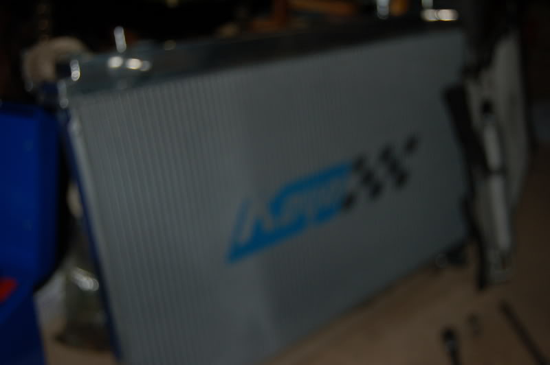
Set up the new radiator, putting the old A/C condensor in front of it.
A little more GOLD:
Brackets too:
Water Pump:
That's all for now. More Friday.
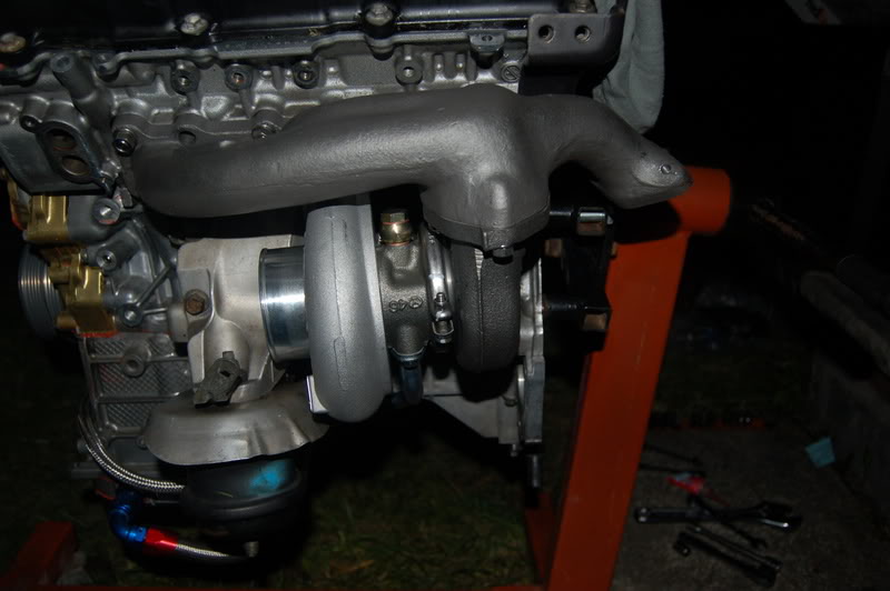
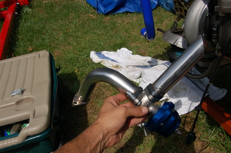
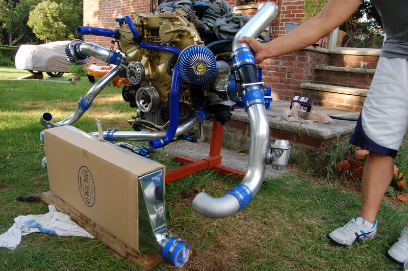
I decided to mock fit the turbo piping to see how it would all line up and if I would need anything additional. Glad I did, because I found a couple of things I needed to fix. Namely the BOV needed a Flange and needed to be welded in place. I found a comfortable home for the new BOV by HKS and decided to get it welded today.
I also test fitted the new Greddy Wastegate relocation kit. Knowing that the Greddy kit has been out for quite some time, we also know its strengths and weaknesses. One known weakness is the location of the wastegate (W/G), so I made a phone call to Scott at SVR Technologies in the west coast. He is very knowledgeable and helped me to get a set of the W/G relocation kits for my ride.
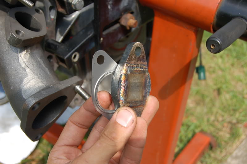
You will se that also. I decided to get additional gaskets to ensure no exhaust leaks in the new set-up.
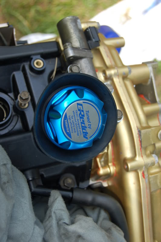
New Greddy Oil Cap:
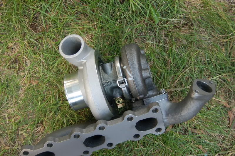
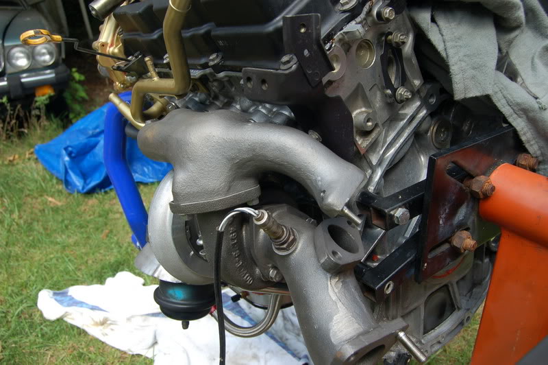
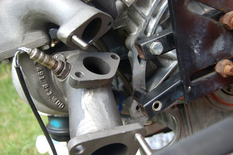
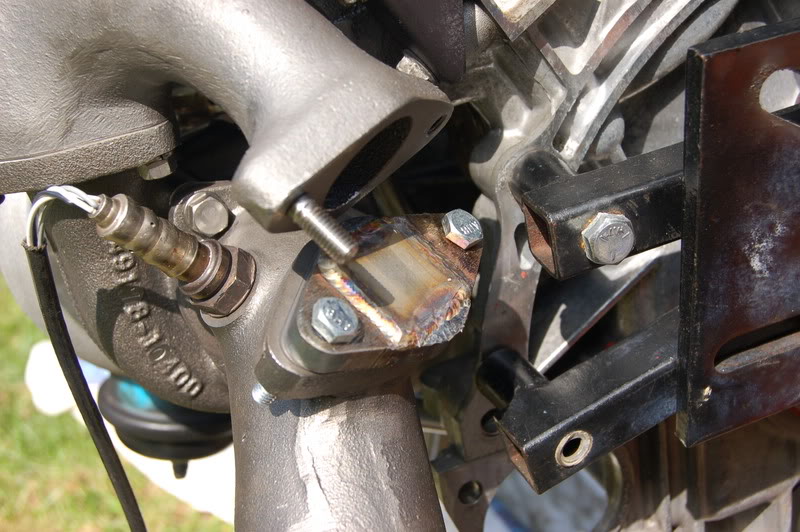
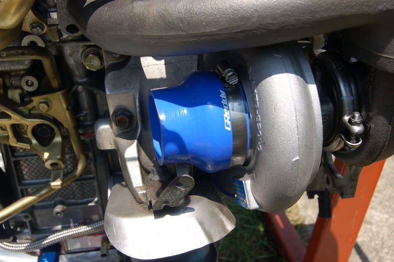
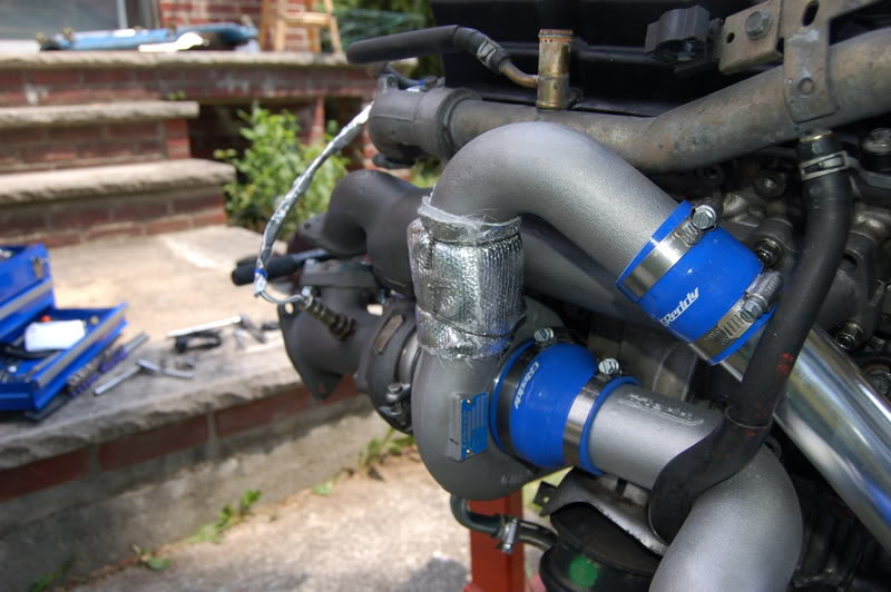
A look at the driver side exhaust manifold:
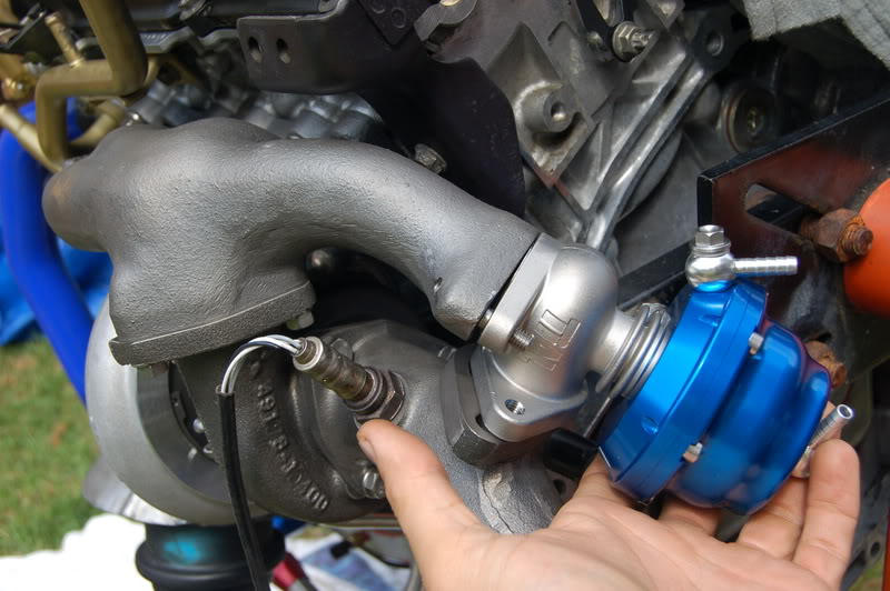
This is where the wastegate was supposed to go...But I said NO! here comes the relocation kit.
You need these caps to close off theold re-entry points: (provided in the kit)
Open dump tubes should sound very nice...
And it should look something like this:
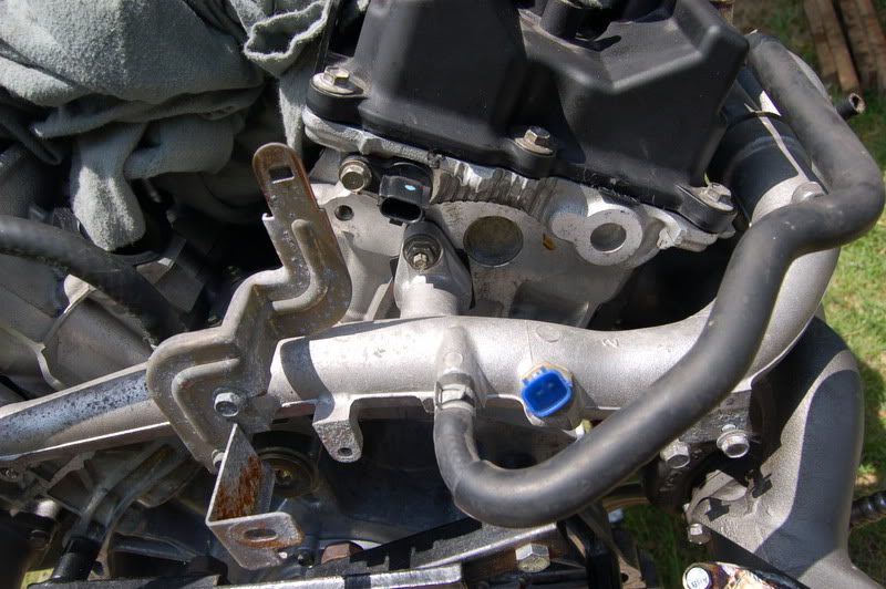
I re-installed the water pipe in the back of the engine...new gaskets also:
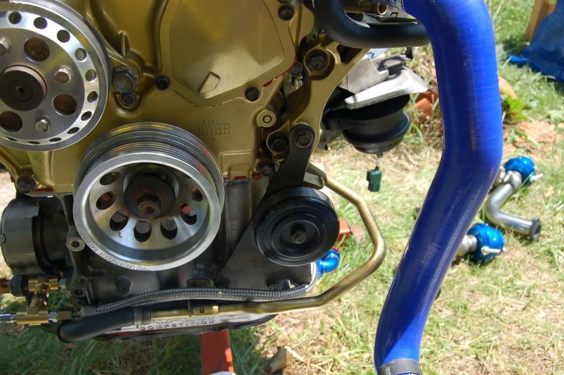
As you can see I put the front mounted pulleys back on:
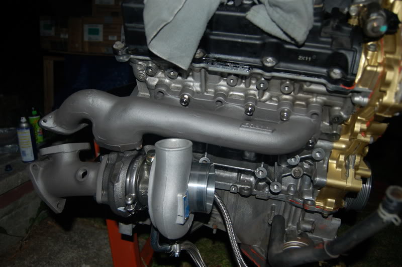
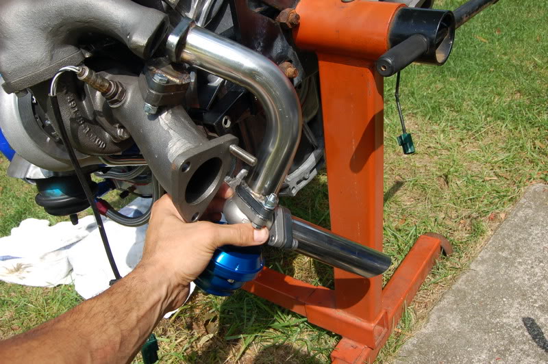
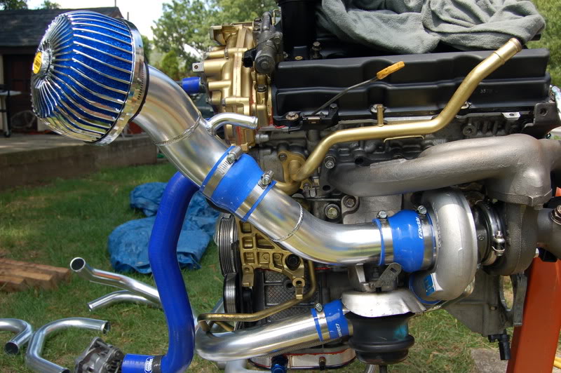
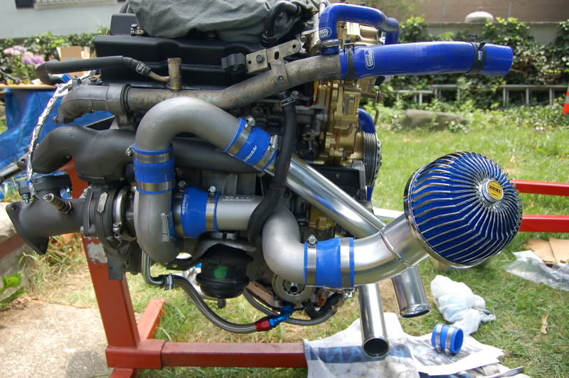
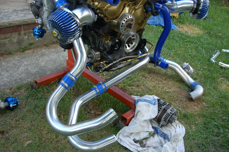
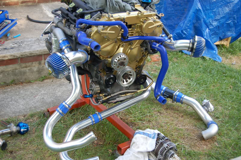
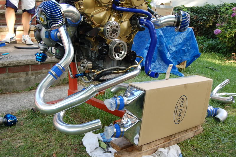
Time to mock up the turbo piping:
The black plastic fitting must go in first, or else it won't work:
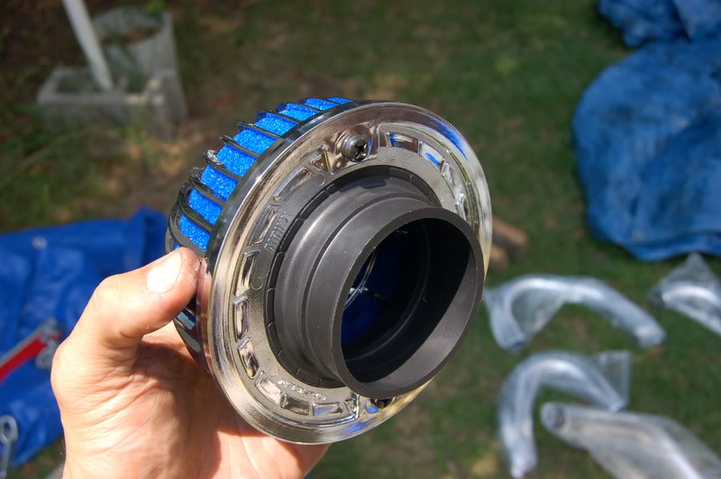
Larger piping goes on the intake:
Should look something like this:
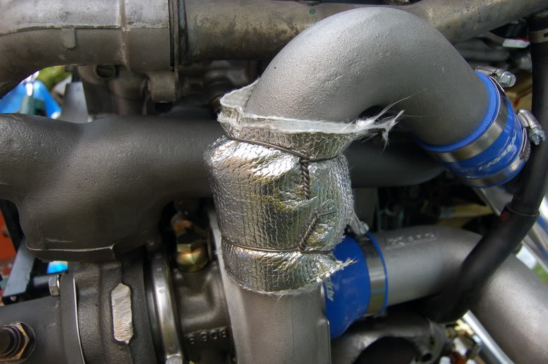
I added a heat shield because the intake piping sat a little too close to the exhaust manifold, which would raise the temperature of the intake charge air unnecessarily:
Close up: Remember to use safety wire and not zip ties, because the zip ties will melt after some time of heat exposure...
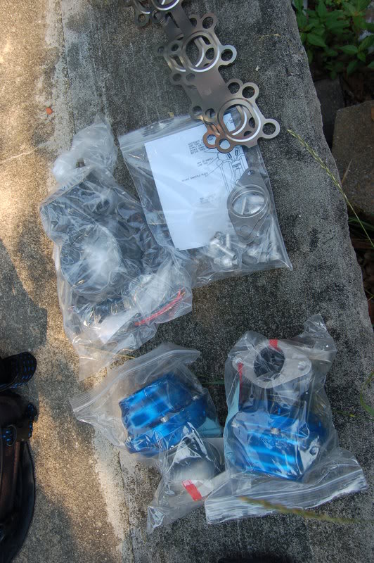
Bling Bling:
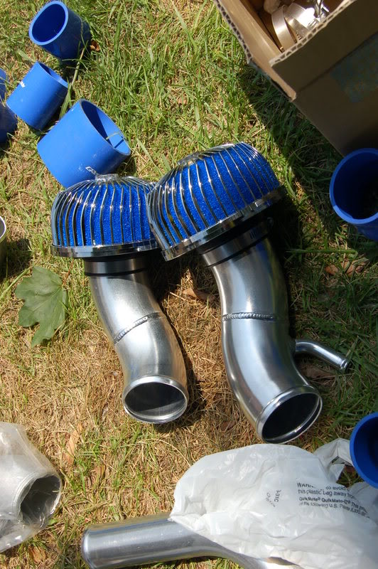
Everything but the inter-cooler:
OK Here's the inter-cooler:
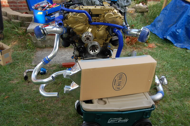
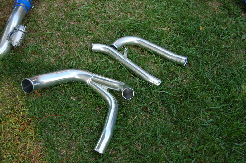
Strangely enough these are extra pipes...Only necessary if you decide to run without the inter-cooler...If you remember the Greddy kit is sold with the inter-cooler as an option.
These pipes won't be used if you use the inter-cooler...JUNK! Took 3 hours and Kevin and Sharif, and Noah to help me figure that one out. DUH!
That's it for today.
Once my clutch comes in, it all goes back together and I'm riding.
I also test fitted the new Greddy Wastegate relocation kit. Knowing that the Greddy kit has been out for quite some time, we also know its strengths and weaknesses. One known weakness is the location of the wastegate (W/G), so I made a phone call to Scott at SVR Technologies in the west coast. He is very knowledgeable and helped me to get a set of the W/G relocation kits for my ride.
You will se that also. I decided to get additional gaskets to ensure no exhaust leaks in the new set-up.
New Greddy Oil Cap:
A look at the driver side exhaust manifold:
This is where the wastegate was supposed to go...But I said NO! here comes the relocation kit.
You need these caps to close off theold re-entry points: (provided in the kit)
Open dump tubes should sound very nice...
And it should look something like this:
I re-installed the water pipe in the back of the engine...new gaskets also:
As you can see I put the front mounted pulleys back on:
Time to mock up the turbo piping:
The black plastic fitting must go in first, or else it won't work:
Larger piping goes on the intake:
Should look something like this:
I added a heat shield because the intake piping sat a little too close to the exhaust manifold, which would raise the temperature of the intake charge air unnecessarily:
Close up: Remember to use safety wire and not zip ties, because the zip ties will melt after some time of heat exposure...
Bling Bling:
Everything but the inter-cooler:
OK Here's the inter-cooler:
Strangely enough these are extra pipes...Only necessary if you decide to run without the inter-cooler...If you remember the Greddy kit is sold with the inter-cooler as an option.
These pipes won't be used if you use the inter-cooler...JUNK! Took 3 hours and Kevin and Sharif, and Noah to help me figure that one out. DUH!
That's it for today.
Once my clutch comes in, it all goes back together and I'm riding.

looking good!!!! I just went through this for my second time. I like the gold paint, I did mine with cast iron gray. Keep us updated I love DIYers.
Ryan
one bit of advice, what I do on the the exhaust side is I take a chisel and Hammer and dent the nut to prevent it from spinning off. Just a old timers trick.
Ryan
one bit of advice, what I do on the the exhaust side is I take a chisel and Hammer and dent the nut to prevent it from spinning off. Just a old timers trick.
Last edited by ryan350z; Jul 28, 2007 at 10:28 AM.
Sorry fellas, but I am gonna have to take a time out for a minute. I am leaving to go get married in Jamaica, I'll be back to finish off this project in 2 weeks.
The suspense is killing me. I can't wait to hear this bad boy start up.
The suspense is killing me. I can't wait to hear this bad boy start up.
Trending Topics
List of mods so far:
2003 350Z
Short Block purchased from Kyle at Import Parts Pro
Consists of Wiseco 8.5:1 compression pistons
Eagle Rods
HKS head gasket
L19 Head studs
Crawford Intake Manifold - Upper Plenum
Greddy Twins
Greddy TT Exhaust
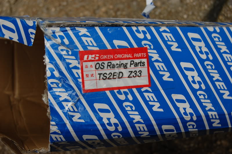
OS Giken Twin Clutch
SVRTech Wastegate Relocation Kit w/open dumps
800cc SARD Injectors
UTEC for Fuel Management
Greddy 1 step colder plugs
AAM Throttle Body Spacer
AAM Oil Pan Spacer
AAM SS Return Lines
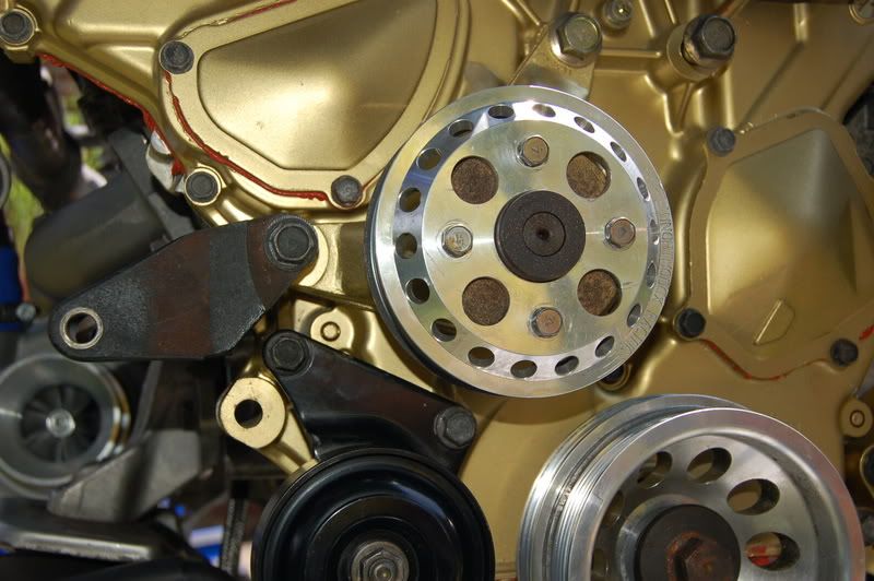
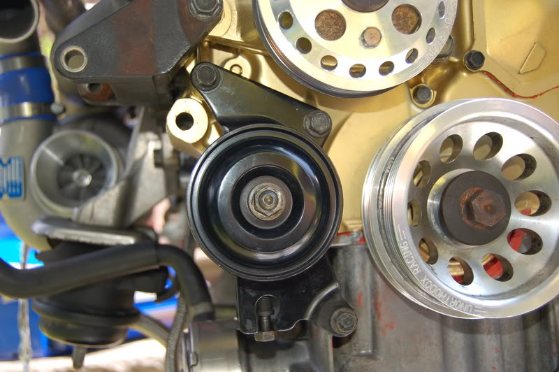
Unorthodox Racing Underdrive Pulleys (Polished)
Samco Hoses
Koyo Racing Radiator
Blitz Radiator Cap
Cusco Catch Can
HKS BOV
HKS EVC VI Boost Controller
I know I'm forgetting a lot, but that about wraps it up for now.
Wish me luck.
2003 350Z
Short Block purchased from Kyle at Import Parts Pro
Consists of Wiseco 8.5:1 compression pistons
Eagle Rods
HKS head gasket
L19 Head studs
Crawford Intake Manifold - Upper Plenum
Greddy Twins
Greddy TT Exhaust
OS Giken Twin Clutch
SVRTech Wastegate Relocation Kit w/open dumps
800cc SARD Injectors
UTEC for Fuel Management
Greddy 1 step colder plugs
AAM Throttle Body Spacer
AAM Oil Pan Spacer
AAM SS Return Lines
Unorthodox Racing Underdrive Pulleys (Polished)
Samco Hoses
Koyo Racing Radiator
Blitz Radiator Cap
Cusco Catch Can
HKS BOV
HKS EVC VI Boost Controller
I know I'm forgetting a lot, but that about wraps it up for now.
Wish me luck.
Here is a little more...
Here is what I did this afternoon after working 16 hours on an ambulance. I was bored. I figured why not put the block back in the car...Easy enough. All I am waiting for at this point is still the never-ending BS with the clutch. I will have it on Monday along with the exhaust.
I figured if I got a head start with the engine I could figure out the harness and have it ready so all that needs to be done is mount the clutch and flywheel and bolt up the transmission.
I also mounted up most of all of the accessories (except the A/C). The harness is a jungle of wires and connectors. I do remember a handful of them, but quite a few of them, I don't...Thankfully Nissan made it very simple by making connectors that don't match, so you can almost never connect something together that isn't supposed to be connected. Whew...lucky me. Or else I'd be in some trouble. I probably should have labeled the harness components too. Labeling the nuts and bolts were a key piece to making sure I didn't lose sny nuts and bolts.
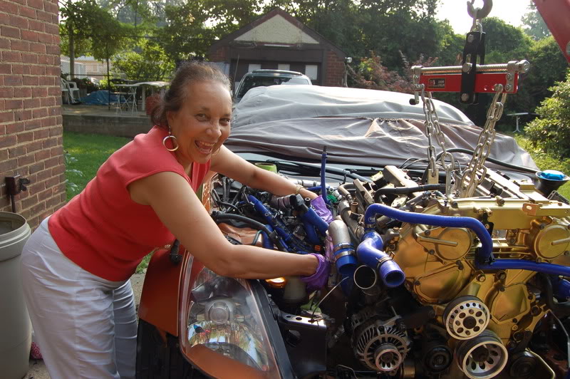
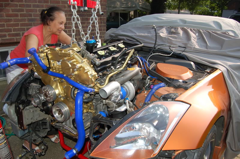
Anyway, Momma ZMedic helped me to make sure I didn't smash into anything important. Funny thing is in the pics, it looks like she is a mechanic. See for yourself.
Here is the car before I got started today.
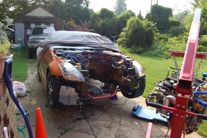
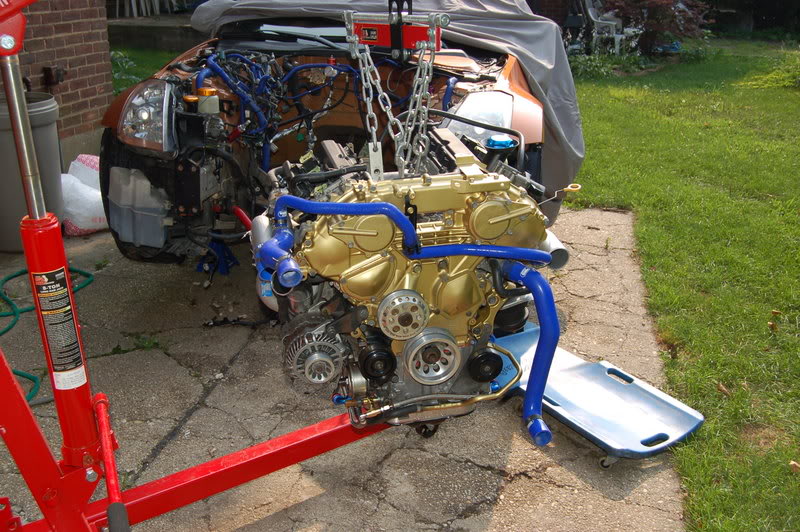
here is the new motor.
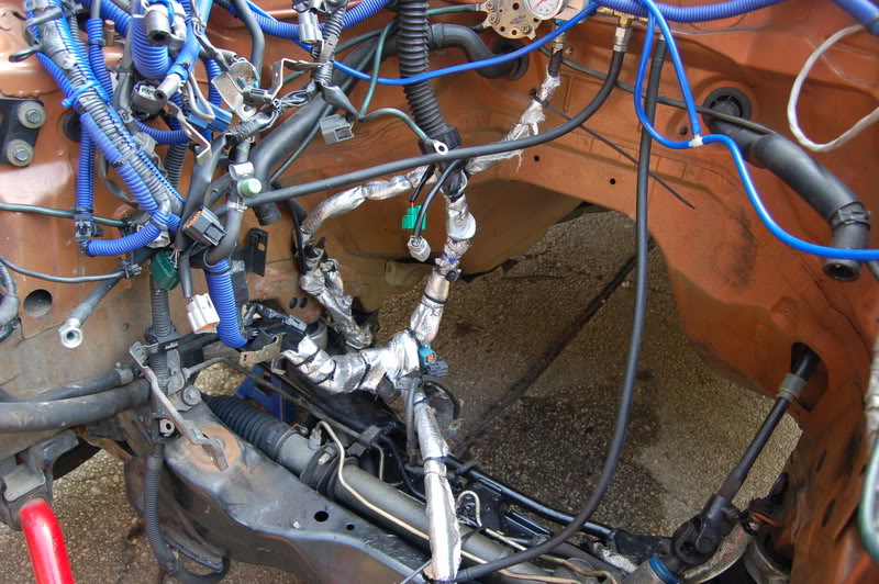
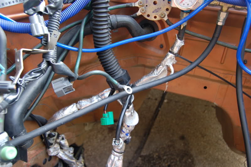
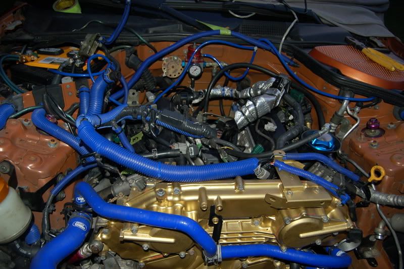
I took the time to do some considerable wire and fuel line heat wrapping for protection. Also not I used safety wire and not zip ties for longevity.
I had no one else available to help me line her up today, so when in doubt call mom.
Bringing her in...easy, easy, easy...
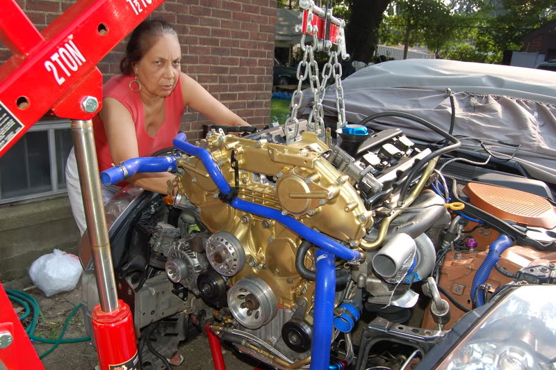
Smile mom, You are making this look too easy.
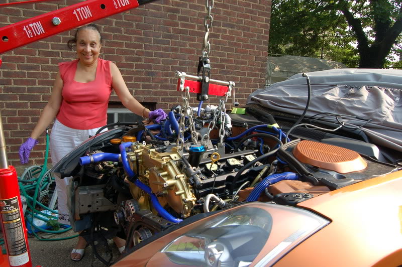
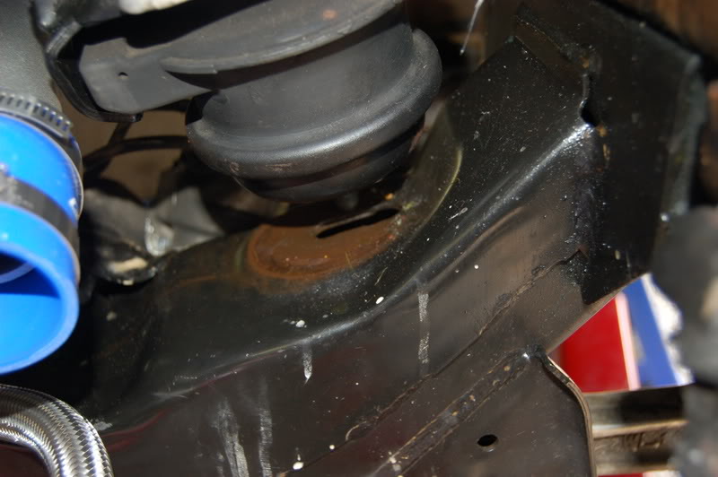
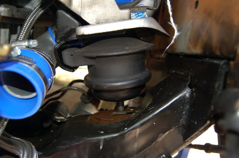
Watch the motor mounts and make sure they line up before you drop her in.
What a mess of wires to sort out.
Thats it for today, night time came all too quickly.
Here is what I did this afternoon after working 16 hours on an ambulance. I was bored. I figured why not put the block back in the car...Easy enough. All I am waiting for at this point is still the never-ending BS with the clutch. I will have it on Monday along with the exhaust.
I figured if I got a head start with the engine I could figure out the harness and have it ready so all that needs to be done is mount the clutch and flywheel and bolt up the transmission.
I also mounted up most of all of the accessories (except the A/C). The harness is a jungle of wires and connectors. I do remember a handful of them, but quite a few of them, I don't...Thankfully Nissan made it very simple by making connectors that don't match, so you can almost never connect something together that isn't supposed to be connected. Whew...lucky me. Or else I'd be in some trouble. I probably should have labeled the harness components too. Labeling the nuts and bolts were a key piece to making sure I didn't lose sny nuts and bolts.
Anyway, Momma ZMedic helped me to make sure I didn't smash into anything important. Funny thing is in the pics, it looks like she is a mechanic. See for yourself.
Here is the car before I got started today.
here is the new motor.
I took the time to do some considerable wire and fuel line heat wrapping for protection. Also not I used safety wire and not zip ties for longevity.
I had no one else available to help me line her up today, so when in doubt call mom.
Bringing her in...easy, easy, easy...
Smile mom, You are making this look too easy.
Watch the motor mounts and make sure they line up before you drop her in.
What a mess of wires to sort out.
Thats it for today, night time came all too quickly.


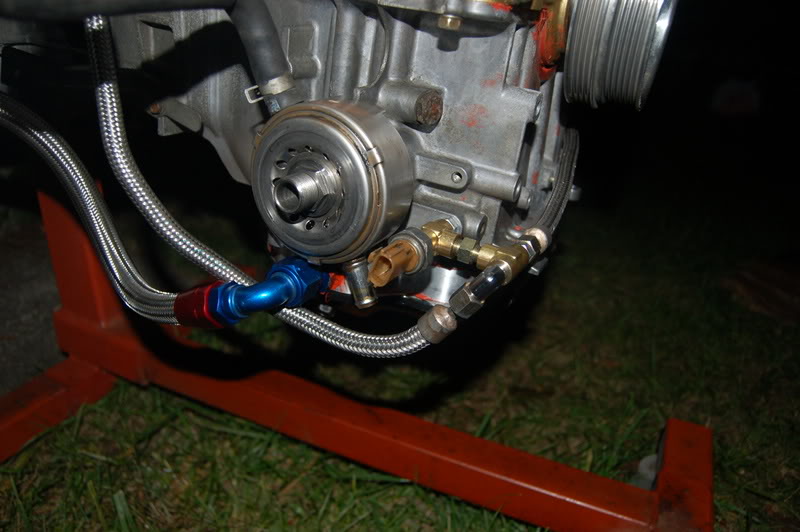
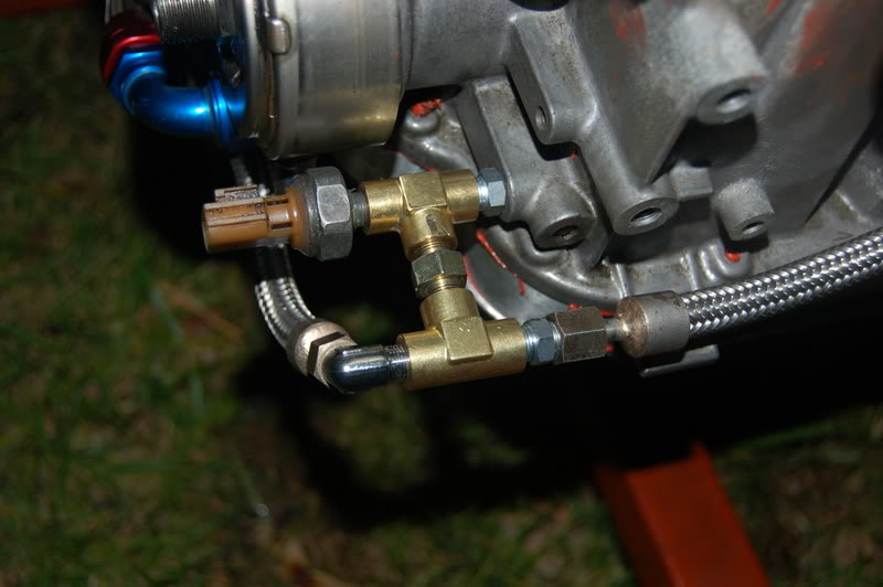
one thing we do different here than the greddy instructions say is to put both tees together and the oil pressure on the end. then we route the driver side under the upper oil pan instead of around the motor, it is plenty long enough and keeps it well out of the way and away from sharp corners where we see the lines get cut up.
nice write up !! this reminds me of how we "used" to do stuff for sure...

I'm back. Married and recovering from my honeymoon! LOL
Hope to get some work done Friday. Looking to install the clutch and flywheel and possibly tranny. Just got my new transmission jack to help in aligning/installing the tranny.
I miss my car so much!!!
Any advice on clutch install
Do I grease the pilot bearing and throw-out bearing ???
Need some advice ASAP. Do's and don't's!!!

Originally Posted by rrmedicx
I'm back. Married and recovering from my honeymoon! LOL
Hope to get some work done Friday. Looking to install the clutch and flywheel and possibly tranny. Just got my new transmission jack to help in aligning/installing the tranny.
I miss my car so much!!!
Any advice on clutch install
Do I grease the pilot bearing and throw-out bearing ???
Need some advice ASAP. Do's and don't's!!!
Hope to get some work done Friday. Looking to install the clutch and flywheel and possibly tranny. Just got my new transmission jack to help in aligning/installing the tranny.
I miss my car so much!!!
Any advice on clutch install
Do I grease the pilot bearing and throw-out bearing ???
Need some advice ASAP. Do's and don't's!!!
I'd also put a thin film of grease on the inside of the throw-out bearing so that it will slide up and down the transmission snout.

Looks good, except I'd be worried about the oil backing up in those turbo oil return lines. It looks like they dip down and start going upward as they feed back into the pan. You want a constant downward flow on those return lines.
As far as the oil return lines, they happen to be very thick SS lines from AAM. I bought them for added security and leak protection, but unfortunately they dont bend very easily. I'll see about that, thanks for the heads up...
I was thinking about taking Jeremy's advice and adjusting the set-up pertaining to the oil sender T's.

Other than that todays effort to accomplish more was ***!!!
I feel like I accomplished absolutely nothing. Apparently the short block I purchased already had a Pilot Bushing in place. But being that I already bought one, I figured why be cheap and take the easy way out, so I attempted to remove the old bushing...Not an easy task without the proper tools. After about 1 hour of fighting with it, I managed to remove it. I replaced it with new one. Pictures to follow. I also had a terrible time with installing the fly wheel...I broke a bolt head off and had to shop for the proper tool to remove the broken half... Good news I got it out with no damage to the crank. If I screwed that one up, I would have to start all over.
So after all of that drama, I decided to call it a short day and continue another day. See pics below.
I was thinking about taking Jeremy's advice and adjusting the set-up pertaining to the oil sender T's.
Other than that todays effort to accomplish more was ***!!!
I feel like I accomplished absolutely nothing. Apparently the short block I purchased already had a Pilot Bushing in place. But being that I already bought one, I figured why be cheap and take the easy way out, so I attempted to remove the old bushing...Not an easy task without the proper tools. After about 1 hour of fighting with it, I managed to remove it. I replaced it with new one. Pictures to follow. I also had a terrible time with installing the fly wheel...I broke a bolt head off and had to shop for the proper tool to remove the broken half... Good news I got it out with no damage to the crank. If I screwed that one up, I would have to start all over.
So after all of that drama, I decided to call it a short day and continue another day. See pics below.
I used to use a large tap to remove pilot bushings.
Start threading the tap into the bronze pilot bushing. Put some grease on it to keep the chips from going all over. Once the tap threads its way into the pilot bushing it will hit the end of the crankshaft... keep turning and the tap will walk the pilot bushing out of the end of the crankshaft.
Start threading the tap into the bronze pilot bushing. Put some grease on it to keep the chips from going all over. Once the tap threads its way into the pilot bushing it will hit the end of the crankshaft... keep turning and the tap will walk the pilot bushing out of the end of the crankshaft.
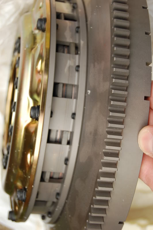
Here we go..Here is the Clutch OS Giken Twin:
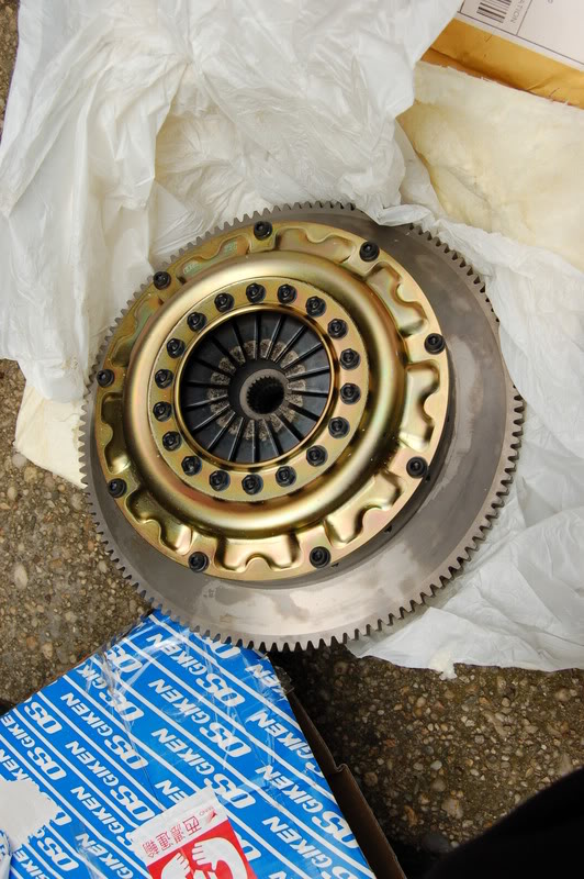
Looks Beautiful
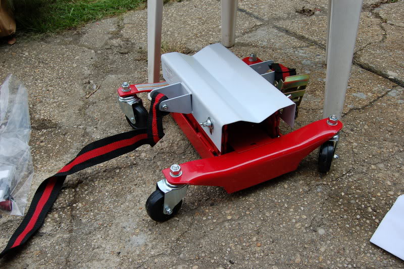
Here is my newly purchased cheapo E-bay Transmission Jack for $35 bucks...
Here is what it looks like now.
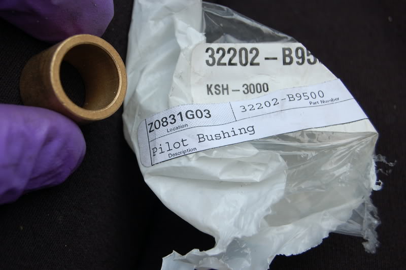
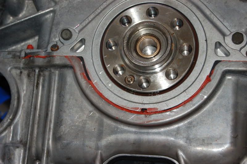
New Pilot Bushing fresh from Nissan
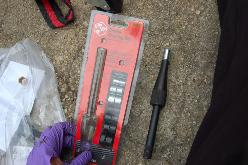
New Universal Clutch alignment tool $37 from Auto Parts Store
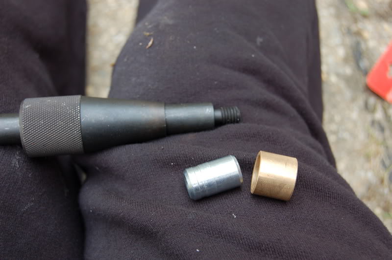
Select the right sized head that fits the Pilot Bushing:
Here we go.
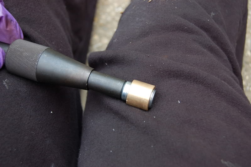
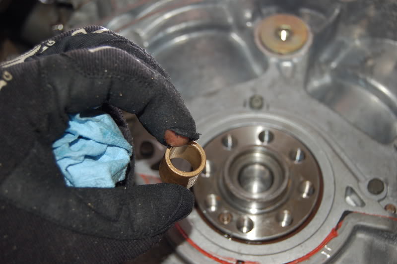
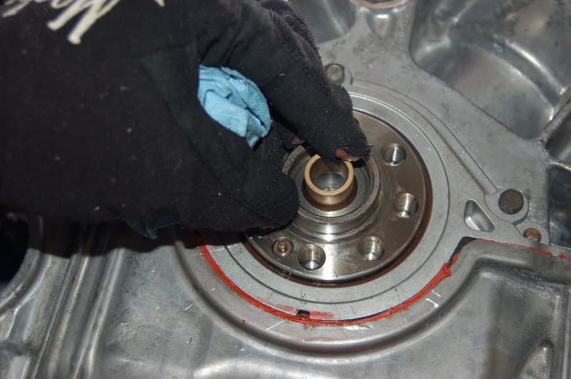
Installing the new pilot bushing...didn't just fall in...required a little lubrication...touch of motor oil, and ease it in with a spark plug socket and light taps of the hammer.
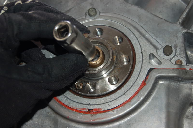
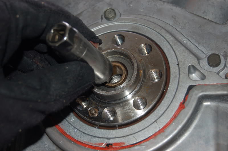
Ready for the Flywheel portion of the new clutch unit.
Look for the tiny Dolly Pin to align the flywheel. The flywheel has only one tiny hole to match up.
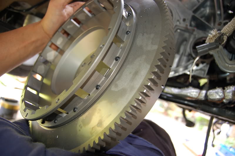
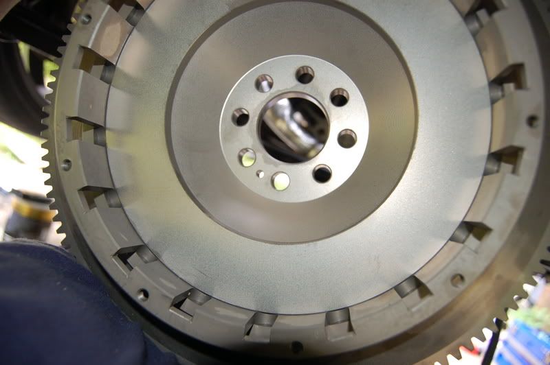
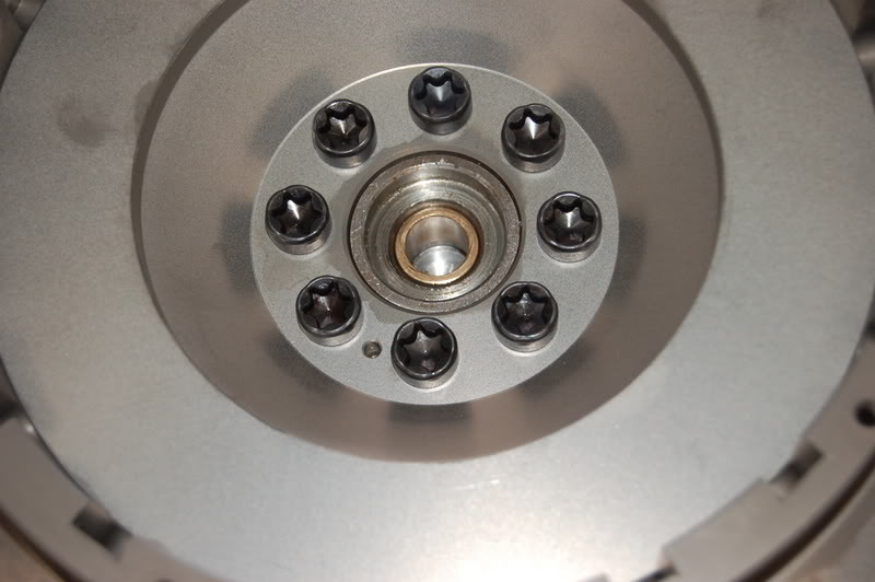
Tighten like you would a spare tire, in opposing sequence. There are 8 bolts which are Torx head #55.
I broke one of the bolts trying to get to 92lbs of torque. I think I will use loctite and go to 85lbs. Hopefully I won't break any more. What a beatch to get out. Well fortunately I got the broken bolt out but I decided to call it quits, since it just started raining.
Looks Beautiful
Here is my newly purchased cheapo E-bay Transmission Jack for $35 bucks...
Here is what it looks like now.
New Pilot Bushing fresh from Nissan
New Universal Clutch alignment tool $37 from Auto Parts Store
Select the right sized head that fits the Pilot Bushing:
Here we go.
Installing the new pilot bushing...didn't just fall in...required a little lubrication...touch of motor oil, and ease it in with a spark plug socket and light taps of the hammer.
Ready for the Flywheel portion of the new clutch unit.
Look for the tiny Dolly Pin to align the flywheel. The flywheel has only one tiny hole to match up.
Tighten like you would a spare tire, in opposing sequence. There are 8 bolts which are Torx head #55.
I broke one of the bolts trying to get to 92lbs of torque. I think I will use loctite and go to 85lbs. Hopefully I won't break any more. What a beatch to get out. Well fortunately I got the broken bolt out but I decided to call it quits, since it just started raining.