TrackPack's Turbo Fab Thread...
#41
what made you design the header to flow towards the back, then reverse that and bring it to the front? Just thinking it would be more efficient if you designed the manifold to flow forward.
#42
Thread Starter
Registered User
iTrader: (1)
Joined: Nov 2006
Posts: 143
Likes: 0
From: Winnipeg, Mb, Canada
Originally Posted by fstrnldr
what made you design the header to flow towards the back, then reverse that and bring it to the front? Just thinking it would be more efficient if you designed the manifold to flow forward.
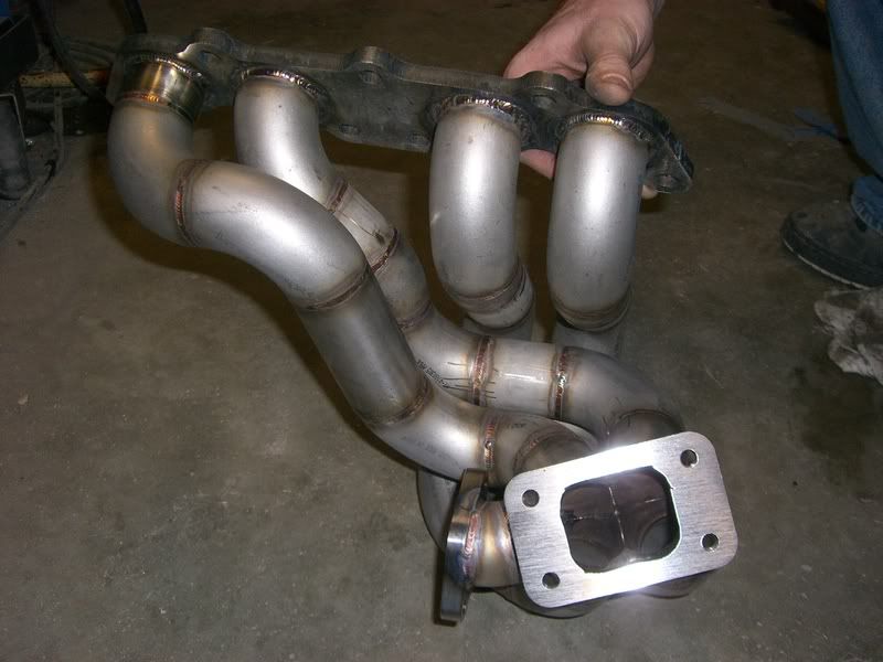
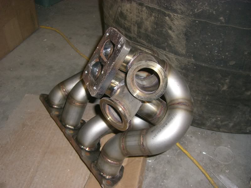
That being said, I wanted to merge both sides of the exhaust as close to the turbo as possible, keeping both banks separated as long as possible, you cant really tell from the pics so far but if you look at the fist pic there, right before the flex is the merge, right above the ac compressor. and in order to merge that late I needed the space provided by going back first, if it went forward first you would have a very hard time getting another tube through(probably imposable with ac..) Plus it increases manifold length on drivers side....that much closer to equal length lol
....manifolds should be twisty anyways.....


keep the comments coming guys! thanks.
#43
Originally Posted by TrackPack
The intent with this project from day one was to build a turbo kit that required removing nothing...

#44
Originally Posted by go-fast
get a lincoln 110 mig to start
The POwerMig 140 unit looks nice, or the SP140T.
#45
Originally Posted by QuadCam
I can't seem to find that model........is that a model or are you suggesting a 110Volt unit?
The POwerMig 140 unit looks nice, or the SP140T.
The POwerMig 140 unit looks nice, or the SP140T.
#46
Thread Starter
Registered User
iTrader: (1)
Joined: Nov 2006
Posts: 143
Likes: 0
From: Winnipeg, Mb, Canada
Originally Posted by rcdash
What a novel concept! Great work! Was that a flexible exhaust section a few posts back going to the wheel well? Are you worried about all the plastics in that area melting? Not sure how the manifolds fit together with the turbos that are way up in front... 

#47
Originally Posted by TrackPack
The intent with this project from day one was to build a turbo kit that required removing nothing and not having to deal with modifying anything like ac lines and the likes. I also intend on having this car as rattle free as it started...
That being said, I wanted to merge both sides of the exhaust as close to the turbo as possible, keeping both banks separated as long as possible, you cant really tell from the pics so far but if you look at the fist pic there, right before the flex is the merge, right above the ac compressor. and in order to merge that late I needed the space provided by going back first, if it went forward first you would have a very hard time getting another tube through(probably imposable with ac..) Plus it increases manifold length on drivers side....that much closer to equal length lol
....manifolds should be twisty anyways.....


keep the comments coming guys! thanks.
That being said, I wanted to merge both sides of the exhaust as close to the turbo as possible, keeping both banks separated as long as possible, you cant really tell from the pics so far but if you look at the fist pic there, right before the flex is the merge, right above the ac compressor. and in order to merge that late I needed the space provided by going back first, if it went forward first you would have a very hard time getting another tube through(probably imposable with ac..) Plus it increases manifold length on drivers side....that much closer to equal length lol
....manifolds should be twisty anyways.....


keep the comments coming guys! thanks.
#48
Originally Posted by 350Z400rwhp
This looks like it is for a bank of 4 cylinders, or am I just not looking at this right? I'm sure you know what you are doing but isn't taking all of that to such a small pipe to the turbo restrictive? Keep this thread up, I love the pics!
#49
Originally Posted by Vq.turbo.DremZ
I am not sure what your referring to but the one you pictured there is for a 4-banger car. And in terms of what your referring to as restrictive, that manifold looks great for a twin scroll turbo, and the vbands for dual wastegates looks BA...
#51
Very nice work, and welding. I'm a fabricator myself and always apreciate good work when I see it. I bet most people on here don't know how long things liket this take. Fabrication is soooooo timeconsuming. I'v been welding tig for a while now and would consider myself as a very good welder, so I know how it goes.. Did you purge all your piping with argon while welding? I hate the crap that can build up on the inside. I fabricated this kit for my other car: http://s137.photobucket.com/albums/q...tboston004.jpg
It's a 97 Ford probe GT with an Eaton M62 supercharger. It runs high 12's (car weighs only 2750lbs full interior) so I'm happy with it.
One day I will probably do something like that with the 350z. Good choice on the 10ga stanless on the headers, that should be bullet proof.
Keep up the good work.
It's a 97 Ford probe GT with an Eaton M62 supercharger. It runs high 12's (car weighs only 2750lbs full interior) so I'm happy with it.
One day I will probably do something like that with the 350z. Good choice on the 10ga stanless on the headers, that should be bullet proof.
Keep up the good work.
Last edited by BoostedProbe; 07-16-2008 at 07:28 PM.
#52
Thread Starter
Registered User
iTrader: (1)
Joined: Nov 2006
Posts: 143
Likes: 0
From: Winnipeg, Mb, Canada
Awesome work on the probe, very innovative! I like that alot, I can appreciate all forms of forced induction an any car, heck I think all cars should be boosted, good work!
As for purging the piping, no that wasnt done but being that the header material is so thick, if you dont penetrate all the way through you shouldnt have that problem, you can also use flux power to prevent that buildup, have you tried it? Flux was used in certain spots in the build.
Thanks guys, keep the comments coming!
ohh and those 2 last pics were just examples of twisty headers, because some one asked about my header design, how it goes back first then forward. sorry for confusion there.
#53
Originally Posted by TrackPack
you can also use flux power to prevent that buildup, have you tried it? Flux was used in certain spots in the build.
I'm in the food processing industry and the welds have to be absolutley perfect, especially when welding tubing. If the weld is bad on the inside it is difficult to wash and there is a chance of baceria growth and contamination.
It's mostly .065 wall so I turn the Amperage down.
With my Probe build accuracy was very important. The transfer shaft hits 15,000rpm at times so everything has to be perfectly alighned. Never had any problems, just have to use hybrid ceramic bearings.
Last edited by BoostedProbe; 07-17-2008 at 01:34 PM.
#56
Thread Starter
Registered User
iTrader: (1)
Joined: Nov 2006
Posts: 143
Likes: 0
From: Winnipeg, Mb, Canada
Originally Posted by wunfstmax
I was thinking of putting my turbo there as well. How do you plan on running the downpipe?
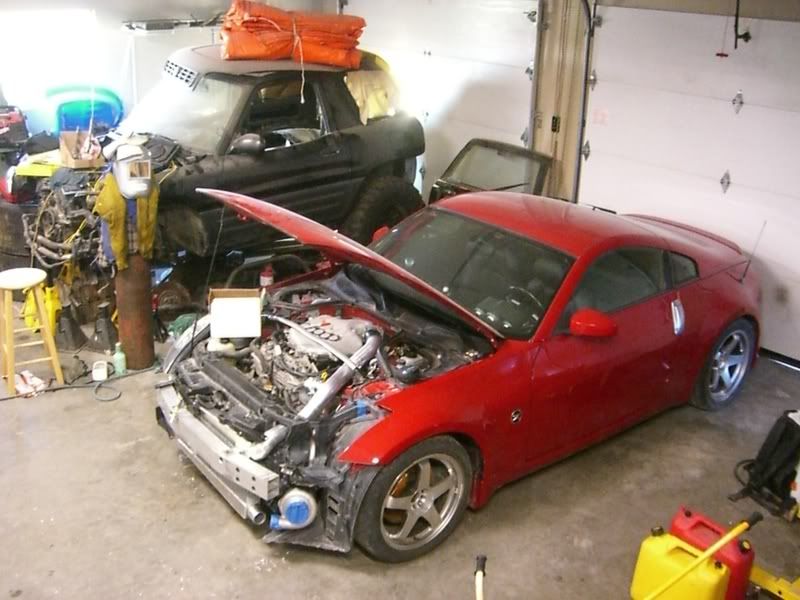
Well guys, heres another terrible quality pic brought to you by non other than myself lol!

Just a far away teaser to show you where the project stands.
Starting to come together nicely, I'll have better pics soon.
later.


