My soon to be 350z in S14 240sx clothing


 01-29-2009, 07:50 PM
#482
Registered User
iTrader: (3)

Join Date: Oct 2007
Location: reading
Posts: 4
Likes: 0
Received 0 Likes
on
0 Posts
great work i just started to do a vq35de in my s14. the only thing imglad about is that i got a donor 350z for 1000 bucks at a junk yard with only 17,000 miles.
keep up the good work
keep up the good work
 01-30-2009, 12:44 PM
#484
Registered User
Thread Starter
iTrader: (5)

Join Date: Apr 2008
Location: Cincinnati, Ohio
Posts: 230
Likes: 0
Received 0 Likes
on
0 Posts
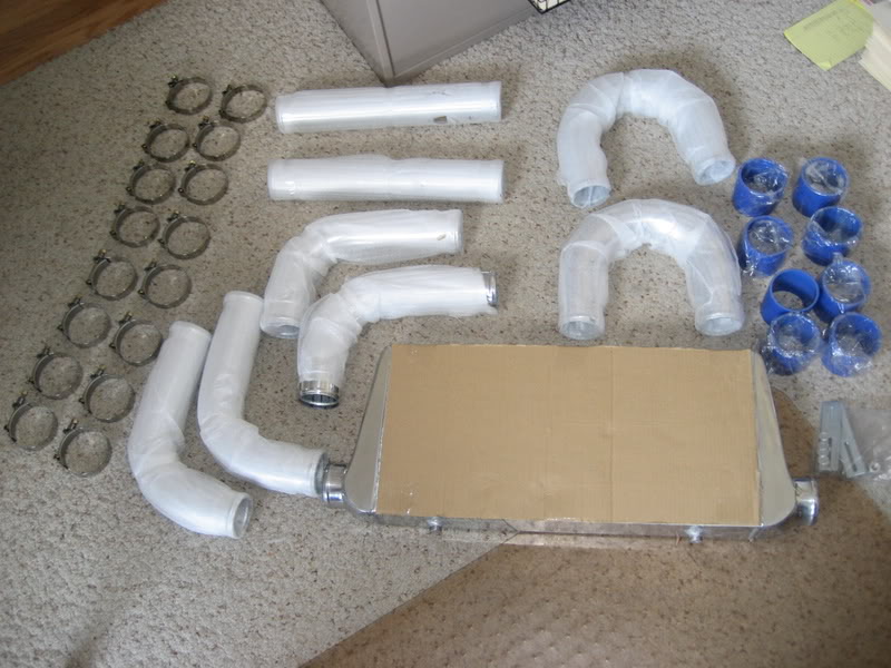
Got these in the mail today, although the blue couplers will be traded out for black ones eventually. Should have it all installed this weekend. Pics soon.

 01-30-2009, 01:56 PM
#486
Registered User

Join Date: Mar 2008
Location: Jacksonville, Fl
Posts: 271
Likes: 0
Received 0 Likes
on
0 Posts
i just saw this thread and all i have to say is you are my hero...every compliment that you got in this thread doesnt even come close to acurately describing your craftsmanship and talent, great job


 02-01-2009, 10:15 AM
#490
Registered User
Thread Starter
iTrader: (5)
Join Date: Apr 2008
Location: Cincinnati, Ohio
Posts: 230
Likes: 0
Received 0 Likes
on
0 Posts
Well I didnt get her all piped in yet due to the fact I was working on my brothers car and mine but I got the intercooler mounted.
DEAR GUY WHO OWNED MY CAR BEFORE ME,
The following is the correct way to cut holes into your chassis for intercooler piping:
Step 1:
Get a drill with a metal hole saw. Make sure metal hole saw is 1/2" bigger in diameter than the intercooler piping you are working with. In my case I used a 3 1/2" hole saw because I am using 3" pipe.
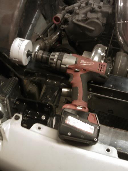
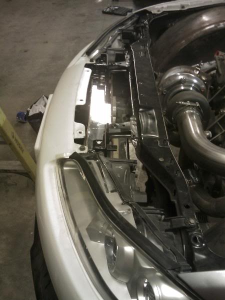
Find out where you want your pipes to go through the chassis and drill. Use a metal file to file down any sharp edges. Mine turned out like so:
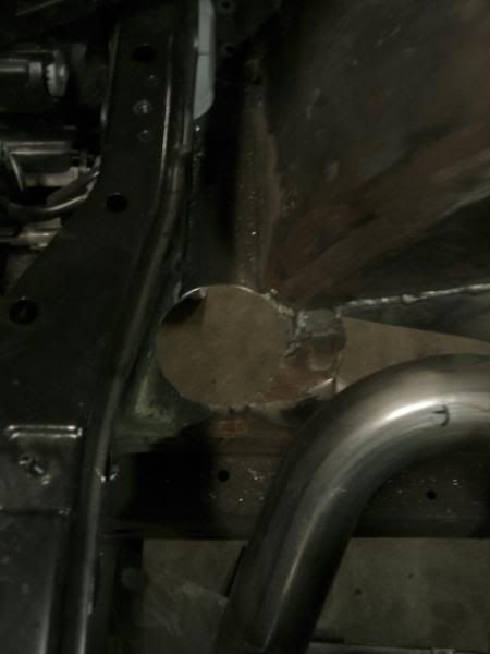
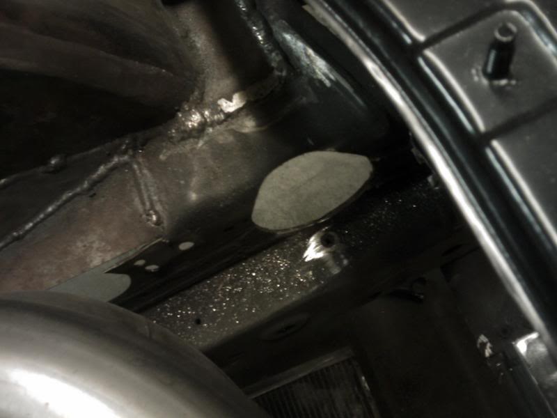
Once you are done, you need to put some sort of plastic or rubber around the hole to keep the intercooler piping from rubbing against the chassis which could eventually cause a hole in the piping. The extra 1/2" in diameter of the hole should allow for this.
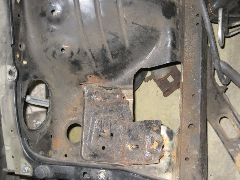
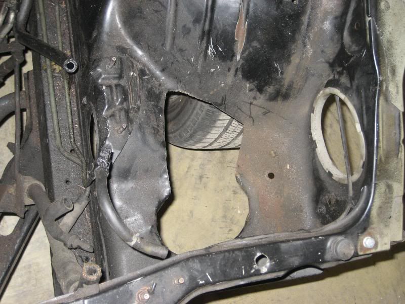
Following these simple directions will keep the engine bay of your chassis from looking chitty and poorly done like this:
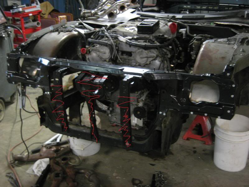
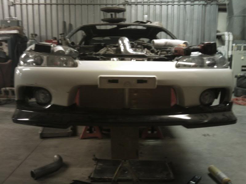
So I cant get over how well this intercooler mounted up to the car the way I wanted it to. The dimensions of the intercooler are 31" long by 12" high by 3" wide with 3" inlets. First thing I had to do was remove the hood latch support. Going to have to come up with a plan to re-mount it as I dont really want to have hood pins if I can avoid it. Second I had to cut the outer supports enough to clear the intercooler but leave enough to support the head light brackets. A microsoft paint rendition of the removing that occured is shown below.
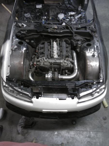
To my suprise I was happy to find out that once this stuff was all removed and I lined the intercooler up with the opening of the front bumper, the intercooler mounting points lined up with both inner headlight brackets. All I had to do was drill holes in the brackets and they bolted up like so:
Not only does the intercooler act as the two reinforcement points that were removed, but it also leaves enough room to cram my radiator, ac condensor and fans in between it and the turbo. Its a real tight fit but I love how it all fell into place.
As of right now I have the intercooler supported from the bottom with a scissors jack and a block of wood until I can get Mike out to weld the metal brackets I have fabricated up to the chassis to support the intercooler from the bottom.
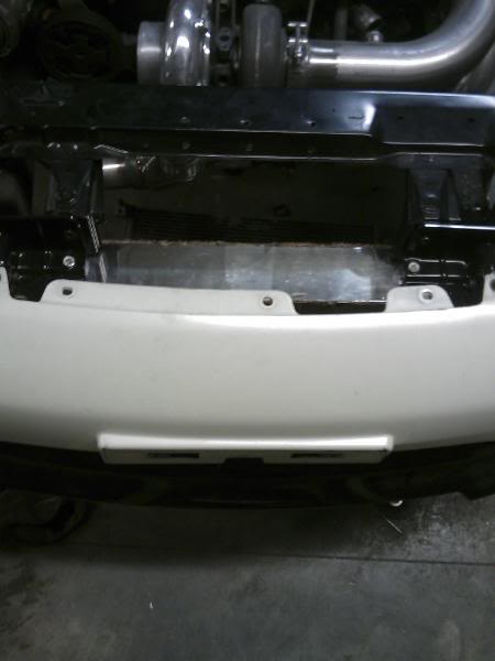
From the front it looks like so:
Side view of the intercooler mounted:
And a random cool shot my brother took:
Once I get the brackets welded to the chassis to support the intercooler then I will run the piping.
Man I am running out of room for stuff in the engine bay, lol.
DEAR GUY WHO OWNED MY CAR BEFORE ME,
The following is the correct way to cut holes into your chassis for intercooler piping:
Step 1:
Get a drill with a metal hole saw. Make sure metal hole saw is 1/2" bigger in diameter than the intercooler piping you are working with. In my case I used a 3 1/2" hole saw because I am using 3" pipe.
Find out where you want your pipes to go through the chassis and drill. Use a metal file to file down any sharp edges. Mine turned out like so:
Once you are done, you need to put some sort of plastic or rubber around the hole to keep the intercooler piping from rubbing against the chassis which could eventually cause a hole in the piping. The extra 1/2" in diameter of the hole should allow for this.
Following these simple directions will keep the engine bay of your chassis from looking chitty and poorly done like this:
So I cant get over how well this intercooler mounted up to the car the way I wanted it to. The dimensions of the intercooler are 31" long by 12" high by 3" wide with 3" inlets. First thing I had to do was remove the hood latch support. Going to have to come up with a plan to re-mount it as I dont really want to have hood pins if I can avoid it. Second I had to cut the outer supports enough to clear the intercooler but leave enough to support the head light brackets. A microsoft paint rendition of the removing that occured is shown below.
To my suprise I was happy to find out that once this stuff was all removed and I lined the intercooler up with the opening of the front bumper, the intercooler mounting points lined up with both inner headlight brackets. All I had to do was drill holes in the brackets and they bolted up like so:
Not only does the intercooler act as the two reinforcement points that were removed, but it also leaves enough room to cram my radiator, ac condensor and fans in between it and the turbo. Its a real tight fit but I love how it all fell into place.
As of right now I have the intercooler supported from the bottom with a scissors jack and a block of wood until I can get Mike out to weld the metal brackets I have fabricated up to the chassis to support the intercooler from the bottom.
From the front it looks like so:
Side view of the intercooler mounted:
And a random cool shot my brother took:
Once I get the brackets welded to the chassis to support the intercooler then I will run the piping.
Man I am running out of room for stuff in the engine bay, lol.
 02-04-2009, 04:53 PM
#494
Registered User
iTrader: (14)

Join Date: Dec 2007
Location: Middletown, DE
Posts: 603
Likes: 0
Received 0 Likes
on
0 Posts
Awesome progress man ... wish I was closer to see this build in person. If you don't wind up with some serious magazine/media coverage after you're done it'd be a damn shame.
 02-04-2009, 07:48 PM
#496
Registered User
Thread Starter
iTrader: (5)
Join Date: Apr 2008
Location: Cincinnati, Ohio
Posts: 230
Likes: 0
Received 0 Likes
on
0 Posts
Yes, yes it does.
On a side note Nissan shafted me literally. Went to see what the progress was on my driveshaft today. Found out literally NOBODY makes an aftermarket u-joint spline setup for the 350z/G35. Nissan uses an odd ball size and the one company that makes it wont sell it because Nissan apparently has the exclusive rights. So what has to happen in order for me to have a shaft made? They have to cut the spline off the end of the driveshaft, weld it to a serviceable american u-joint setup since Nissans u-joints arent serviceable. Then machine it smooth so it can be mated to a 3 1/2" diameter driveshaft with heavy duty u-joints to handle 700+ hp. Because of all the labor it makes the shaft expensive. Thanks Nissan.
02-04-2009, 08:58 PM
#499
Phenom

iTrader: (17)
Join Date: Aug 2005
Location: Greenville SC
Posts: 8,639
Likes: 0
Received 0 Likes
on
0 Posts
Dude, you, your car, and this entire thread wreak of awesome. I can't wait to see this thing on the road. So many times projects like this grind to a halt half way through, but its so refreshing to see you making steady progress and seeing through to completion.