
Crankcase Ventilation Mod w/Pics

 04-01-2010 | 09:40 AM
#82
Using 2 breathers right on the valve covers pretty much eliminates any chance of crankcase pressure build up and will work just fine. I like a fresh air pull through set up a bit better since it doesn't smell as much, helps to actively pull fuel vapors out, and helps to maintain vacuum in the crankcase for better ring sealing during idle/cruise (consider the pressure differential between the crankcase and combustion chamber during decel - oil will move in that direction).
I think for any FI setup, drilling out the PCV and opening up the driver's side valve cover orifice a bit is always helpful. My driver's side valve cover hasn't been touched, so that is a point of restriction in my setup which I haven't addressed because the setup is working fine as is. As blow by increases with engine age, I may need to drill that out...
I think for any FI setup, drilling out the PCV and opening up the driver's side valve cover orifice a bit is always helpful. My driver's side valve cover hasn't been touched, so that is a point of restriction in my setup which I haven't addressed because the setup is working fine as is. As blow by increases with engine age, I may need to drill that out...
Last edited by rcdash; 04-01-2010 at 09:43 AM.

 04-01-2010 | 10:35 AM
#84

Well I thought I would post some pics of my vent system, havent done any testing with it yet. It may be overkill though. I plan on capping the fittings on the rear of the valve covers and only using it if I have to. the valve covers are tapped for -8 AN fittings, no check valves. let me know what you guys think....
04-01-2010 | 11:19 AM
#85
^ya thats way overkill and overly complicated. but will work nonetheless
although, i think its been shown that the turbos dont draw enough vacuum to prevent smoking.
although, i think its been shown that the turbos dont draw enough vacuum to prevent smoking.
Last edited by str8dum1; 04-01-2010 at 11:21 AM.
04-01-2010 | 11:51 AM
#86
Well the greddy only uses the drivers side inlet to pull vacuum under boost. Now each turbo will pull from their own valve cover, it should be enough, but if not then I will put breathers on the rear valve covers. I ran open breathers on my turbo ford probe and also had the oil smell, just trying to eliminate that.
04-03-2010 | 06:08 AM
#87

Updating this thread after receiving a PM. The above worked but is overly complicated and not necessary (for me). I realized this by actually logging crankcase pressure (well catch can pressure actually). I was seeing crankcase pressure as high as 4 psi, running 15 psi of boost for less than 10 seconds, depending on various plumbing configurations! Read on for a method that minimizes this...
My current set up entails having a breather filter on the drilled out PCV nipple on the passenger side. This breather is designed to allow fresh air into the crankcase unless blow by is excessive (happens under extended boost conditions - I've data logged it!). The driver's side valve cover vent has a 1/2" heater hose connection that goes to my single greddy square catch can up front. That catch can is stuffed with a sponge to trap oil vapor and the outlet goes to a tee fitting. One end of the tee has a check valve and goes to the plenum port. The other end of the tee also has a check valve and goes to the driver's side turbo air intake piping (this is required for me because of my recirculating bov that dumps air into that tube on throttle lift).
This set up works well (crank case pressure reaches max 1 psi even with extended boost) and eliminates smoking issues I've had in the past. With the tubing and check valves I have in place I draw about 4-6 mm Hg (2-3 psi) of vacuum during idle, which helps to maintain piston ring seal during idle/low load conditions. I think the mirror image of my current set up will work also (swapping driver's side and passenger's side valve cover functions) but I haven't had a chance to actually test it and data log it. The size and length of tubing used has a direct impact on ability to evacuate crankcase pressure!

I have the filter on the passenger side near the firewall but the valve cover nipple is not bored out to increase inside diameter.

So if I put in a T fitting/check valve in that hose and route it to the catch can where is the 2nd hose to the catch can going to go?
Here?

This is why Revups burn oil because the piston ring does not seal at idle?
Last edited by Andrei; 04-03-2010 at 06:44 AM.
04-03-2010 | 06:44 AM
#88

^^
That is what I did kinda. I put a breather on the back of the driver side cover and where the PCV was. I drilled the PCV out though. I actually ran two individual hoses from the inner portion of the valve cover (where you show a T) all the way to a catch can. Worked great! SP does the same thing as you show on their race car.
I had my catch can receiving suction from the inlet of the turbo on my car.
04-03-2010 | 06:47 AM
#90
^^
That is what I did kinda. I put a breather on the back of the driver side cover and where the PCV was. I drilled the PCV out though. I actually ran two individual hoses from the inner portion of the valve cover (where you show a T) all the way to a catch can. Worked great! SP does the same thing as you show on their race car.
I had my catch can receiving suction from the inlet of the turbo on my car.
That is what I did kinda. I put a breather on the back of the driver side cover and where the PCV was. I drilled the PCV out though. I actually ran two individual hoses from the inner portion of the valve cover (where you show a T) all the way to a catch can. Worked great! SP does the same thing as you show on their race car.
I had my catch can receiving suction from the inlet of the turbo on my car.
 I'm interested in rcdash's setup since he said he has low crankcase pressure at idle to seal the piston rings.
04-03-2010 | 06:57 AM
I'm interested in rcdash's setup since he said he has low crankcase pressure at idle to seal the piston rings.
04-03-2010 | 06:57 AM
#91

You can see the two 1/2" hoses come from the center of the valve covers near the fuel rails. They go to a swirl pot catch can that I have tucked in the front bump under the headlight. The catch can is about 12" tall and 6" in diameter with twin inlets that are at an angle to promote spinning of air with internal baffles to keep the air in suspension as long as possible. Then there is a large suction tube which you can see is the -12AN fitting that is on the intake of the turbo.
That suction tube pulls a vacuum through the the valve covers like crazy. Fresh air is brought in through the breather filters on each cover, one of which you can see on the passenger side cover where the PCV should be.
04-03-2010 | 09:16 AM
#92
Quamen, I'd be interested to know how much oil you pull into your catch can with your setup. When I tapped into the cross over hose between valve covers, I ended up pulling out more oil than I anticipated. Perhaps those nipples are not internally baffled as well as the PCV nipples?
Last edited by rcdash; 04-03-2010 at 07:51 PM.
04-03-2010 | 08:43 PM
#93

^^
That is what I did kinda. I put a breather on the back of the driver side cover and where the PCV was. I drilled the PCV out though. I actually ran two individual hoses from the inner portion of the valve cover (where you show a T) all the way to a catch can. Worked great! SP does the same thing as you show on their race car.
I had my catch can receiving suction from the inlet of the turbo on my car.
That is what I did kinda. I put a breather on the back of the driver side cover and where the PCV was. I drilled the PCV out though. I actually ran two individual hoses from the inner portion of the valve cover (where you show a T) all the way to a catch can. Worked great! SP does the same thing as you show on their race car.
I had my catch can receiving suction from the inlet of the turbo on my car.
I was just planning the two breathers in the same location as you, removing the PCV and the back of the DS valve cover. I wasn't planning on seeing if a catch can is required or not, although i have had one sitting in my garage for about a year now maybe I should just put it in.
If I use the catch can I was thinking of a breather in place of the PCV leave the hose that connects the 2 covers. Have a hose from the DS rear valve cover to a catch can from the catch can to the turbo feed pipe that way it still should see some vacuum? I was thinking of filling the catch can with steel wool to hopefully soak up the oil in the vapors or else it might be the same as no catch can at all
 what do you guys think of that idea? Everything seems complex I want to keep it simple without hoses running all over.
Last edited by Sylvan Lake V35; 04-04-2010 at 07:28 AM.
04-03-2010 | 10:20 PM
#94
It's better to do have it setup like rcdash since he data logged pressure and it's proven so better wait for pics tomorrow.
Check this out on my mothers Murano with 66k miles. Only 6k past the 60k warranty.
Unplugged only one side so the other side could be worse. Oil is leaking in all 3 tubes. 66k miles is ********.


Check this out on my mothers Murano with 66k miles. Only 6k past the 60k warranty.
Unplugged only one side so the other side could be worse. Oil is leaking in all 3 tubes. 66k miles is ********.
Last edited by Andrei; 04-03-2010 at 10:26 PM.
04-04-2010 | 07:30 AM
#95
It's better to do have it setup like rcdash since he data logged pressure and it's proven so better wait for pics tomorrow.
Check this out on my mothers Murano with 66k miles. Only 6k past the 60k warranty.
Unplugged only one side so the other side could be worse. Oil is leaking in all 3 tubes. 66k miles is ********.
Check this out on my mothers Murano with 66k miles. Only 6k past the 60k warranty.
Unplugged only one side so the other side could be worse. Oil is leaking in all 3 tubes. 66k miles is ********.
I would change out the valve covers ASAP before the coil packs swell up from the oil and you will end up replacing them as well $$$$$$$$.
04-04-2010 | 07:34 AM
#96
04-04-2010 | 07:40 AM
#97
I had one of the o-rings go on my Titan and I never changed it right away the oil caused the coil pack to "swell" or something of that nature and I ended up haveing to replace a coil pack as well. Trust me it is alot cheaper to do just the valve covers, the coil packs are not cheap. I would make sure you tell you mom it is a possibility if she lets it go too long.
04-04-2010 | 01:59 PM
#98
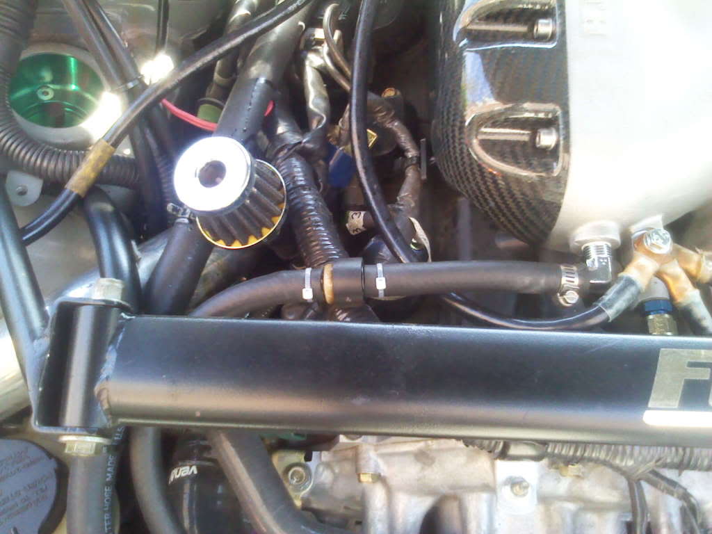
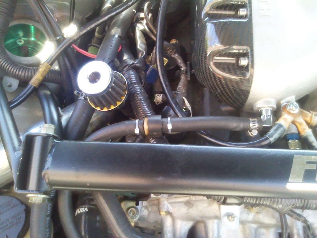
Okay, I think these are the two best pics that reflect my current setup. There's no good way to take a pic of the 1/2" hose going to the driver's side rear port, but suffice to say it just goes directly to the catch can and travels to the left of the breather as pictured below.
Here you can see the breather, the 1/2" hose going to the driver's side port on its left and the check valve on the right going to the intake manifold:
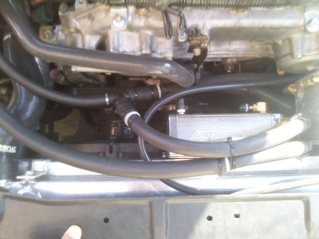
Here is the catch can with the t-junction also pictured, that sucks gases both into the intake manifold and driver's side turbo intake.

Here you can see the breather, the 1/2" hose going to the driver's side port on its left and the check valve on the right going to the intake manifold:
Here is the catch can with the t-junction also pictured, that sucks gases both into the intake manifold and driver's side turbo intake.
04-04-2010 | 10:20 PM
#100

Okay, I think these are the two best pics that reflect my current setup. There's no good way to take a pic of the 1/2" hose going to the driver's side rear port, but suffice to say it just goes directly to the catch can and travels to the left of the breather as pictured below.
Here you can see the breather, the 1/2" hose going to the driver's side port on its left and the check valve on the right going to the intake manifold:
Here is the catch can with the t-junction also pictured, that sucks gases both into the intake manifold and driver's side turbo intake.
Here you can see the breather, the 1/2" hose going to the driver's side port on its left and the check valve on the right going to the intake manifold:
Here is the catch can with the t-junction also pictured, that sucks gases both into the intake manifold and driver's side turbo intake.
can you plz draw a diagram,and mark how you place the check vavle.???