New winter new turbo build


I have a boner for these threads, being bored at work reading the old thread and now the new thread in 2 days does it for me... Nice work, i am interested in getting this kit however the wife is not, but that is a different subject!
Last edited by ErkTheJerk73; Dec 29, 2009 at 05:41 AM.


Couple more things that I have not coverd. This is what I really went to school for and where most of my attention to detail originates from. I made the electrical system for the scavenge pumps as simple as possible. Basically all one needs to be able to do is follow the labled wires and pull/plug a fues in:
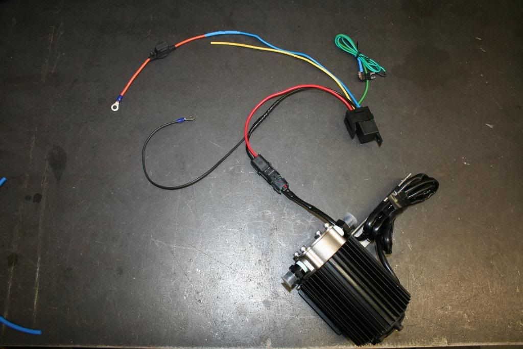
The relay:
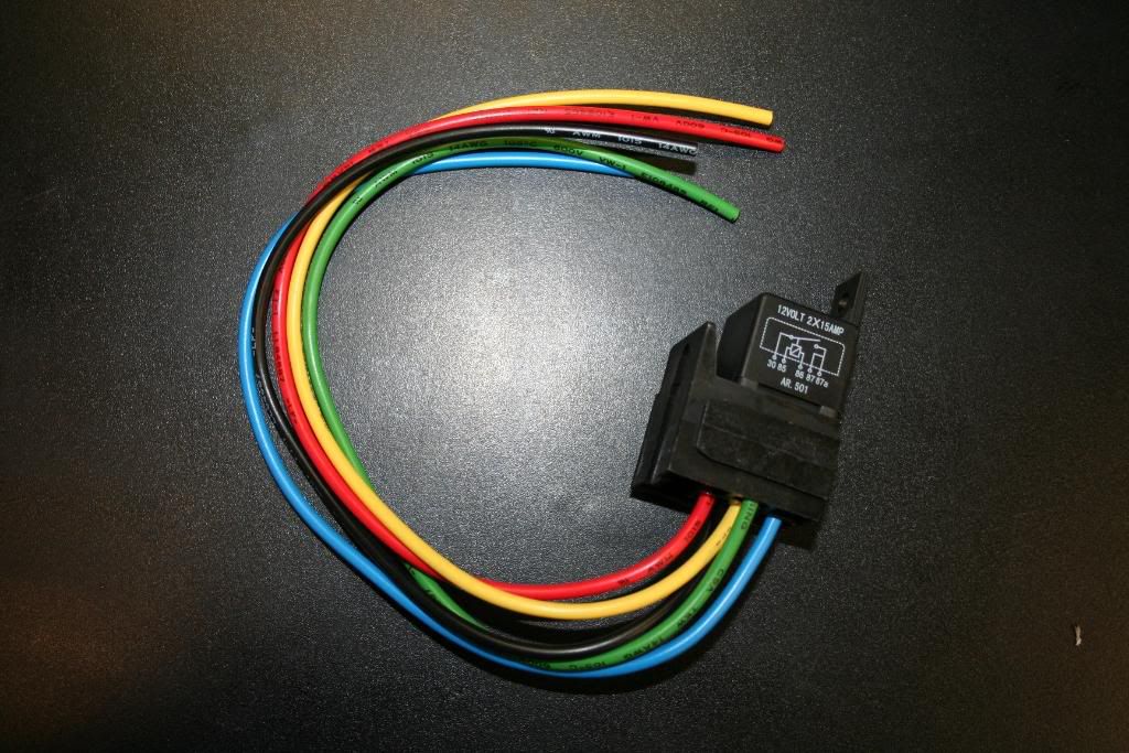
Pin 30 to +12 power (battery)
Pin 85 +V is signal on off (plug to OEM fuse box)
Pin 86 Chassy ground or negative battery terminal
Pin 87 Scavenge pump power
Pin 87a (yellow) spare, I would suggest one runs the power for boost gauge and wideband off of this. This is a good idea because if you loose your lights on the boost gauge/wideband you know that your fuse is blown and scavenge pump is not running. This is how I ran my setup for a year and it works great. Never had blown fuses either, and it is highly unlikely that it will happen.
Water tight connector kit:
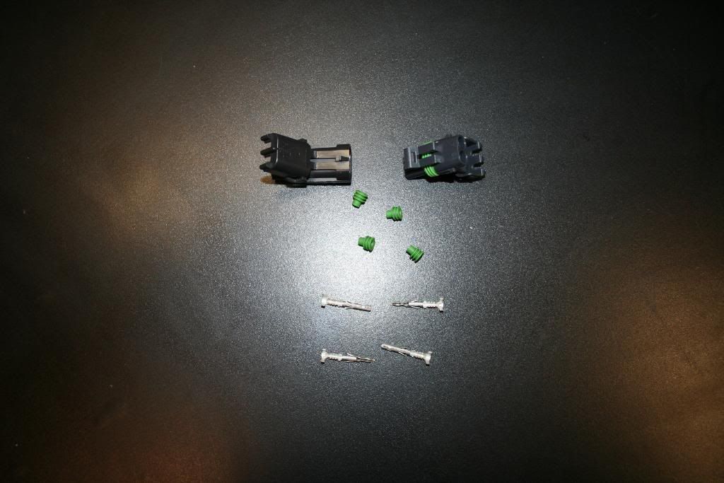
I did not just crimp them on there, I also soldere evrything once crimped. No chance of ever seperating.

Connector done:
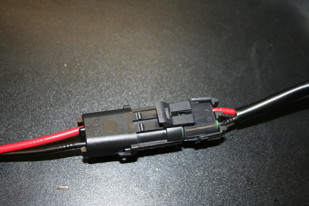
Very important to "tin" the wires before soldering them together. This ensures that the entire wire has been coverd with solder, making it much stronger once soldered to another wire.

This is my favorite thing. It is an "Add a circuit kit" and allows one to add to the existing OEM circuit without affecting them at all. It simply plugs in to the fuse box and provides you with additional output signal. In this case it is pluge in to the windshield washer circuit. The 10A fuse used to be where the "add a circuit" connector goes, and by pluging it in where it is, it remains as a part of the OEM circuit. The 5A fuse is for the new relay on/off signal.
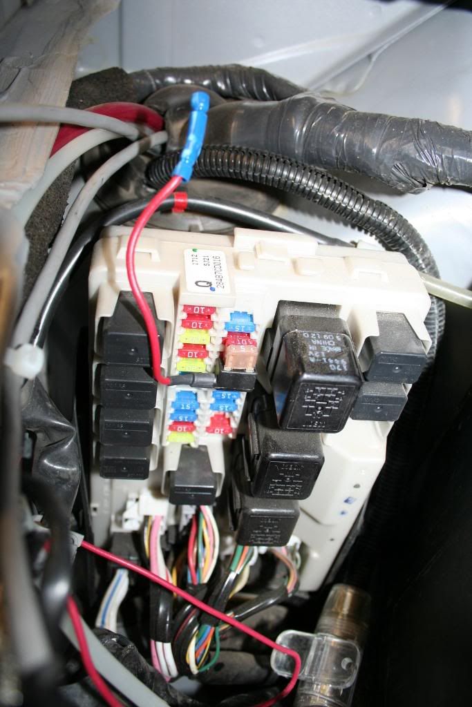
Tested and working, this is how it will be setup/premade ready to go. Like mentioned above, the yellow wire is an additional +12v circuit and I would suggest running the boost gauge/wideband off of it. Very much a plug and play setup:
The relay:
Pin 30 to +12 power (battery)
Pin 85 +V is signal on off (plug to OEM fuse box)
Pin 86 Chassy ground or negative battery terminal
Pin 87 Scavenge pump power
Pin 87a (yellow) spare, I would suggest one runs the power for boost gauge and wideband off of this. This is a good idea because if you loose your lights on the boost gauge/wideband you know that your fuse is blown and scavenge pump is not running. This is how I ran my setup for a year and it works great. Never had blown fuses either, and it is highly unlikely that it will happen.
Water tight connector kit:
I did not just crimp them on there, I also soldere evrything once crimped. No chance of ever seperating.
Connector done:
Very important to "tin" the wires before soldering them together. This ensures that the entire wire has been coverd with solder, making it much stronger once soldered to another wire.
This is my favorite thing. It is an "Add a circuit kit" and allows one to add to the existing OEM circuit without affecting them at all. It simply plugs in to the fuse box and provides you with additional output signal. In this case it is pluge in to the windshield washer circuit. The 10A fuse used to be where the "add a circuit" connector goes, and by pluging it in where it is, it remains as a part of the OEM circuit. The 5A fuse is for the new relay on/off signal.
Tested and working, this is how it will be setup/premade ready to go. Like mentioned above, the yellow wire is an additional +12v circuit and I would suggest running the boost gauge/wideband off of it. Very much a plug and play setup:
Last edited by BoostedProbe; Dec 30, 2009 at 11:49 AM.


 Nice job!


I would rather use a woodhead connector than the ones your using if they are to be under the car. Those type of connectors will get water in them. I used to do electronics on oil rigs, and we used those. They had a much higher failure rate than the wood head type connectors.
I would rather use a woodhead connector than the ones your using if they are to be under the car. Those type of connectors will get water in them. I used to do electronics on oil rigs, and we used those. They had a much higher failure rate than the wood head type connectors.


Some good news. Look like Osiris/Uprev will be the EMS for the kit. I have been talking with them the last couple of days and we have a deal.
Looking at about $5400 (maybe less) for a complete kit.
I am also seting up a vendor account for my350z.com at this time, so I should be good to go by the end of next week.
Looking at about $5400 (maybe less) for a complete kit.
I am also seting up a vendor account for my350z.com at this time, so I should be good to go by the end of next week.
I actually screwd up a bit. It was suposed to be on the oppisite side of the BOV. Hard to explain but it's done.
The breather is there to allow the oil to drain in to the reservoir after the car has been shut off. If it wasn't there, the oil would just sit inside the bearing housing of the turbo. If you leave it sitting it eventually leaks past the seals in to the compressor housing. Doesn't damage the seals at all, it just seeps through overnigh. If the breather wasn't there, the air that the oil displases has no place to go.
The breather is there to allow the oil to drain in to the reservoir after the car has been shut off. If it wasn't there, the oil would just sit inside the bearing housing of the turbo. If you leave it sitting it eventually leaks past the seals in to the compressor housing. Doesn't damage the seals at all, it just seeps through overnigh. If the breather wasn't there, the air that the oil displases has no place to go.
Can't air come in through the seals? If oil can go out, air surely must be able to come in. Did your testing indicate that the breather really was necessary? Perhaps you would end up pulling the oil off the bearings and that would not be good from the point of start up wear and tear. Never mind...
 I just wonder if oil will saturate the breather at some point and start dripping (probably not if it's pointed up)?
Last edited by rcdash; Jan 8, 2010 at 07:10 AM.
Thank you, I really tried to make things as simple as posible. I am a perfectionist.
The air can come through the seals but not fast enough. As the oil suply line drains, it displaces more air than the seals can allow to pass. The reservoir is there to simulate traditional gravity draining to the oil pan, and yes I did do the tests. It works well, I had no sighns of oil in my IC piping at all.
Keep in mind that you can't really pull the oil from the bearing. Top is pressure side, botom is drain. The oil has to go through the bearing, it's the only way out. So no, it would not cause additionlal ware, the pump shuts off with the ignition. Whatever is left in the turbo will drain, just like it would on a top mount turbo setup.
As far as saturation, the kit will come with a hose. So if you are worried about someting like that, you can just run the hose to your catch can. There is a solution for everything...
Can't air come in through the seals? If oil can go out, air surely must be able to come in. Did your testing indicate that the breather really was necessary? Perhaps you would end up pulling the oil off the bearings and that would not be good from the point of start up wear and tear. Never mind... I just wonder if oil will saturate the breather at some point and start dripping (probably not if it's pointed up)?
I just wonder if oil will saturate the breather at some point and start dripping (probably not if it's pointed up)?Keep in mind that you can't really pull the oil from the bearing. Top is pressure side, botom is drain. The oil has to go through the bearing, it's the only way out. So no, it would not cause additionlal ware, the pump shuts off with the ignition. Whatever is left in the turbo will drain, just like it would on a top mount turbo setup.
As far as saturation, the kit will come with a hose. So if you are worried about someting like that, you can just run the hose to your catch can. There is a solution for everything...

That solution involves people that don't work on cars themselves to stop questioning crap.
Like stated by sasha, the reservoir will allow the turbo to drain just like a top mount. People aren't having problems with vortech superchargers or powerlab kits draining do they?
Like stated by sasha, the reservoir will allow the turbo to drain just like a top mount. People aren't having problems with vortech superchargers or powerlab kits draining do they?
 I didn't pay him to say that. It's all right though, every time someone questiones something it makes me think. That is a good thing, because it never hurts to rethink something for the 10th time.
 I think I have been very thoroughl with everything. There won't by any issues.
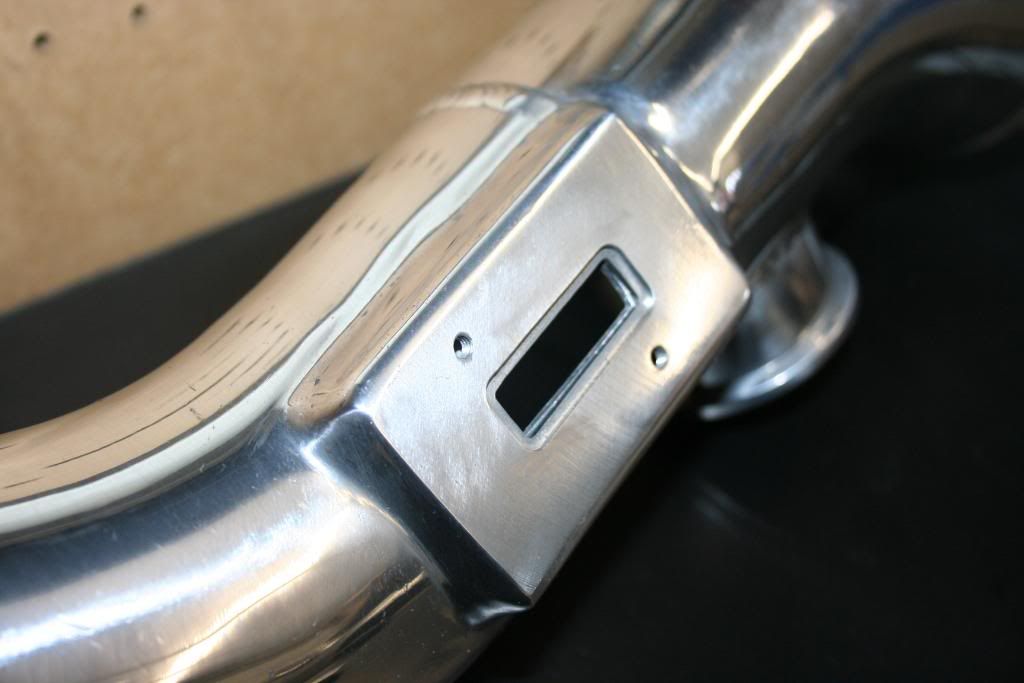
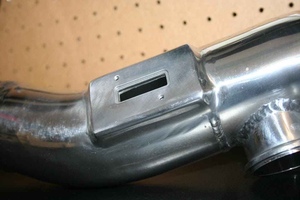
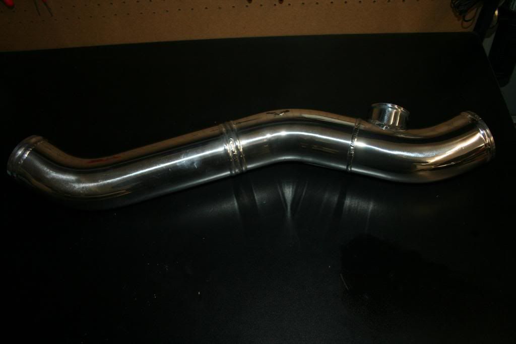
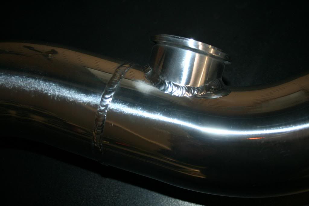
On a side note, I just love the way the MAF sensor housing turned out. Couple of good pictures: