
New winter new turbo build


A few more shots:
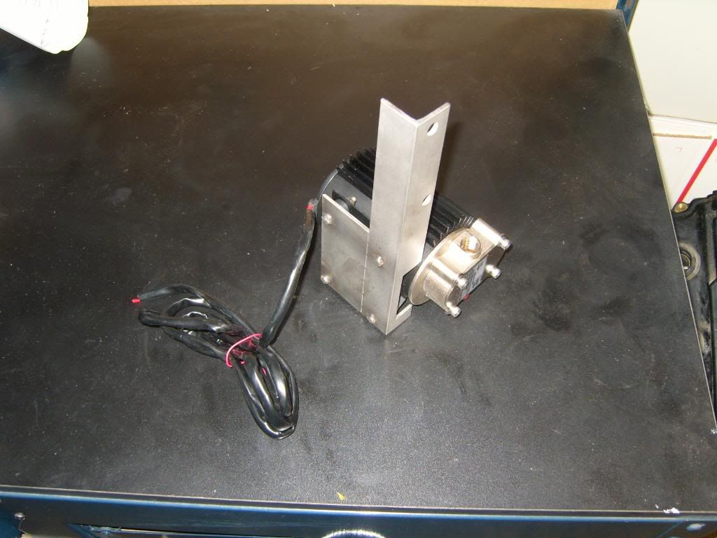
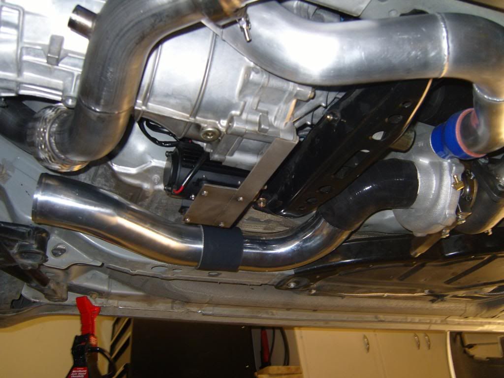
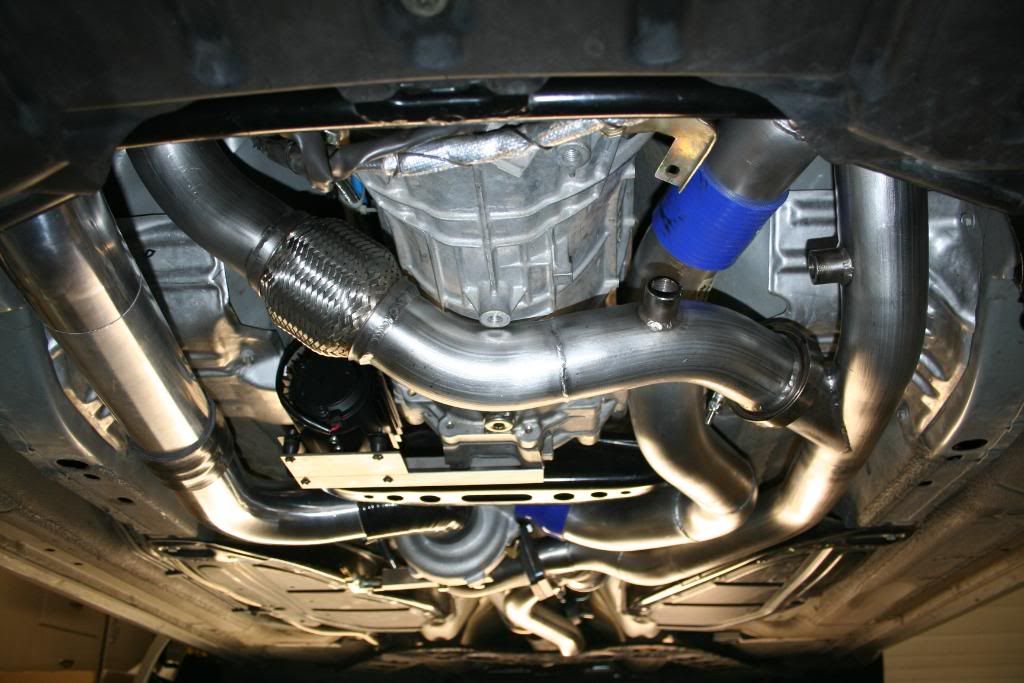
Scavenge pump bracket:
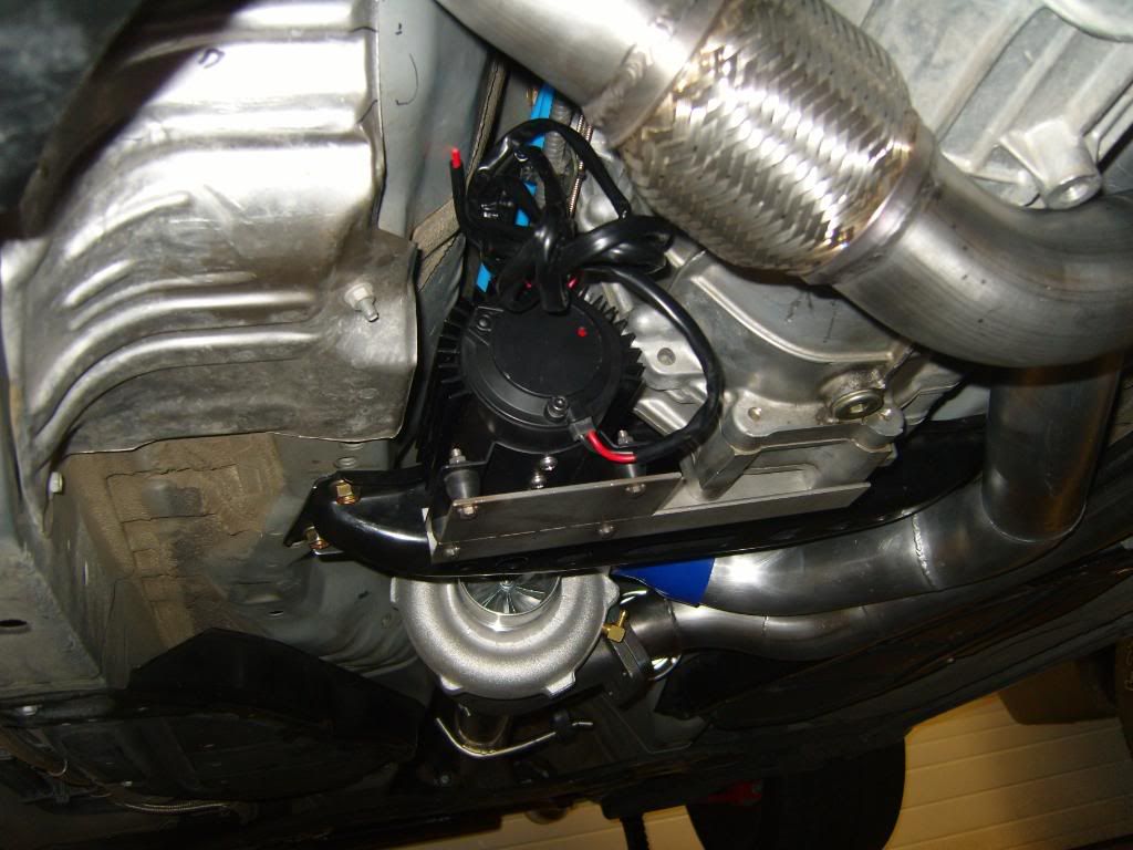
Installed:
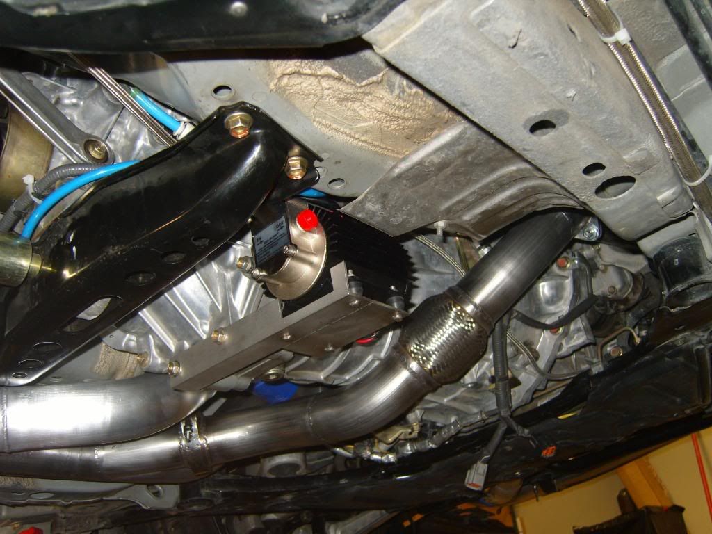
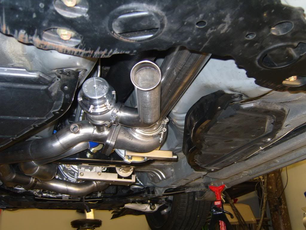
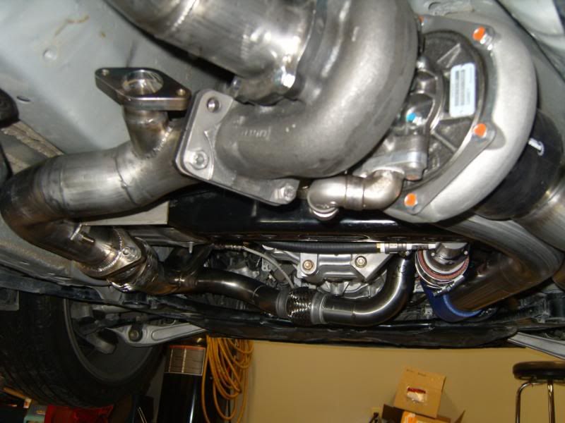
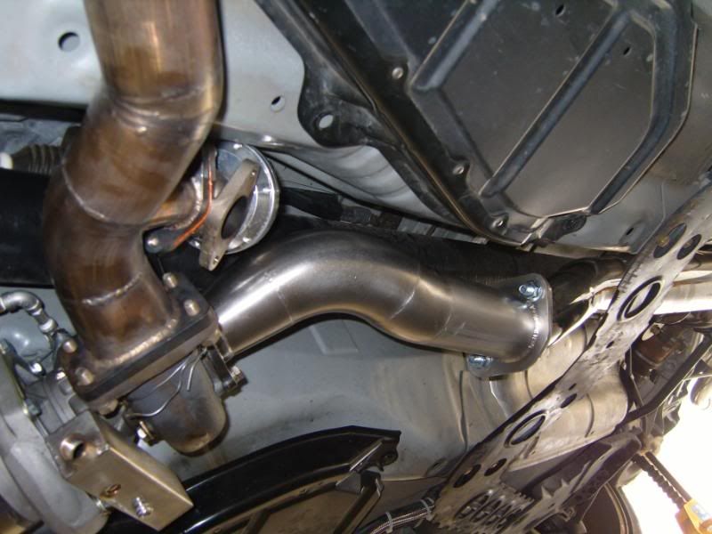
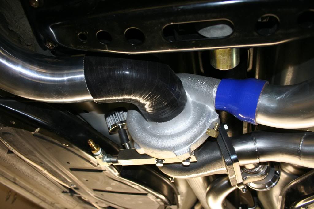
Dump pipe:

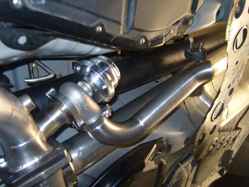
You can see the O2 sensor bung, intended for a wideband just before the waste gate:
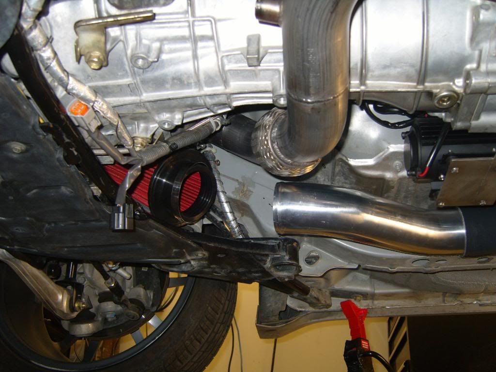
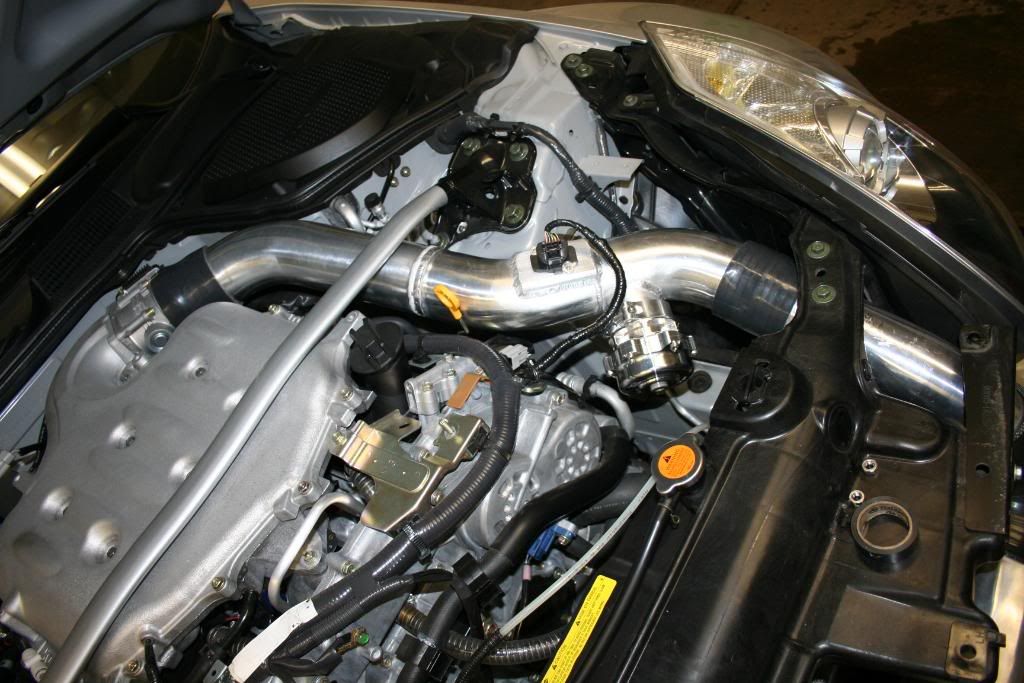
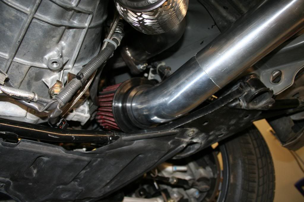
Going to the air filter:
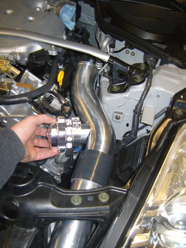
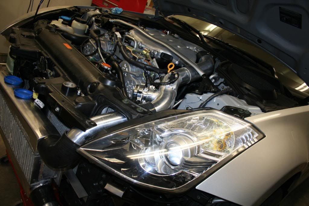
IC to TB finally comming together. I just got the new shipment of 3" piping. The stuff after the coupler will be one pipe:
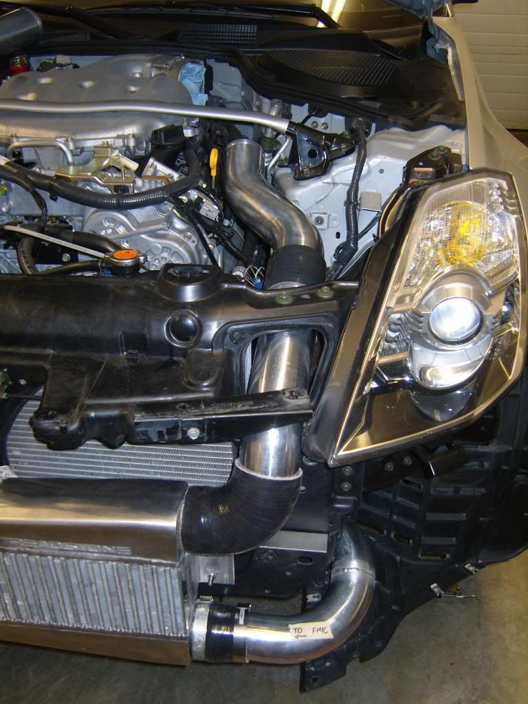
BOV will go here:
Scavenge pump bracket:
Installed:
Dump pipe:
You can see the O2 sensor bung, intended for a wideband just before the waste gate:
Going to the air filter:
IC to TB finally comming together. I just got the new shipment of 3" piping. The stuff after the coupler will be one pipe:
BOV will go here:
Last edited by BoostedProbe; Dec 21, 2009 at 08:56 PM.


Registered User
Joined: Dec 2002
Posts: 498
Likes: 0
From: USA
This kit looks great. The exhaust routing makes more sense than TN's routing, no 180 bends or unneccessary distances. But the intake position is too low imo. When you drive through water there's a chance that it'll suck in water.
That's what I thought.
To be honest i photochoped all the pictures in this thread. I have sooooo much time to just sit there and play on the computer.
Thanks. I think that this setup has less combined piping than any other ST kit out there. The big advantage being the hot side of the setup.
The filter you see in the picture above is sitting low because it is not attached to anything. The pipe you see going to it has to be extended, and the filter will sit beside the starter, below the passenger side header.
No chance of picking up any water.
To be honest i photochoped all the pictures in this thread. I have sooooo much time to just sit there and play on the computer.
No chance of picking up any water.
Last edited by BoostedProbe; Dec 22, 2009 at 06:35 AM.

you might have some boost creep with the wastegate mounted like that. watch it closely.it would be better to move it away from the turbo a bit and change the angle of the inlet.
Last edited by tig488; Dec 22, 2009 at 11:03 AM.

Found a couple of pictures from the old build:
The angle is a bit different, though. But the wastegate is bigger as well. From what I understand, the pressure in the exhaust before the turbo can get to 10psi. With that much pressure, and the wastegate opening, it will vent just fine.
Then I see what the "pros" do:
http://hktuning.com/Ready/CivicTurboManifold.jpg
http://image.dhgate.com/upload/20093...6069440895.jpg
Last edited by BoostedProbe; Dec 22, 2009 at 01:16 PM.


3/8" hose from turbo to pump (about 14"), pump to engine 3/8" hose
(about 3').
The kit wil come with a JWT oil pan spacer, and it will be taped to 3/8" NPT just beside the oil filter. No need to tap upper OEM oil pan.
It's all good. To be honest, I wouldn't even know how to photoshop it in there.
Last edited by BoostedProbe; Dec 22, 2009 at 05:01 PM.

Thank you for pointing that out, valid point. I had the identical setup running only 4.5psi with an even smaller wastegate (38mm vs current 44mm). I had no issues with boost creep at all, on a comparable size turbo.
Found a couple of pictures from the old build:
The angle is a bit different, though. But the wastegate is bigger as well. From what I understand, the pressure in the exhaust before the turbo can get to 10psi. With that much pressure, and the wastegate opening, it will vent just fine.
Then I see what the "pros" do:
http://hktuning.com/Ready/CivicTurboManifold.jpg
http://image.dhgate.com/upload/20093...6069440895.jpg
just here to help, remember im the one that told you to make the oil reservoir. its best to have your WG travel perpendicular with your manifold if possible, yours looks like it actually has a slight angle the opposite direction. im sure it will be fine, but id hate for you to build the entire kit, have some overboost or creep, then have to redo it. in your prior kit it is on a perpendicular angle.

I understand the physics behind the angle at which the w/g is located. If it's at the "wrong angle" it will act like a ventury and won't vent.
For this particular kit, the customer requested that I use the 44mm w/g. It is a bit larger than the 38mm so fitment is a bit of a P.I.T.A. I may change it after all, I will sleep better, even though I don't think it will be a problem in this case.
For the other kits I will use the new Tial 38mm V-band waste gate. It is much smaller than the old style, see link below:
http://www.xtremefabrications.com/st...an_compare.jpg
These will be very easy to fit in thre.
A few more pics. IC to TB piping with the MAFs sensor adapter welded in place:

Also added a breather to the reservoir under the turbo:

I contacted the manufacturer of the Exa scavenge pumps to see if I can reverse the direction. Now, I know with a DC motor it's just a matter of reversing the polarity, and since it is a gear pump it shouldn't be a problem at all. After talking to them, we agreed that it is ok.
Just to make sure, I rigged it up in the garage to a spare battery and some new engine oil. With the polarity reversed it pumps/draws the same as with "suggested" polarity. So I am good to go there. With the pump sitting where it does, this will make the oil line routing a bit simpler.
Turbo intake side of things:

Mase of piping, all in it's place, nice and high:
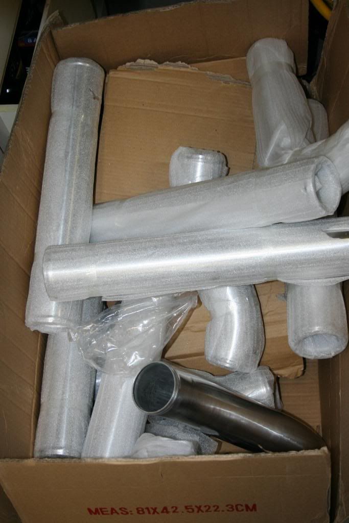
I had a ton of stuff show up today, enough to do a few more of these:

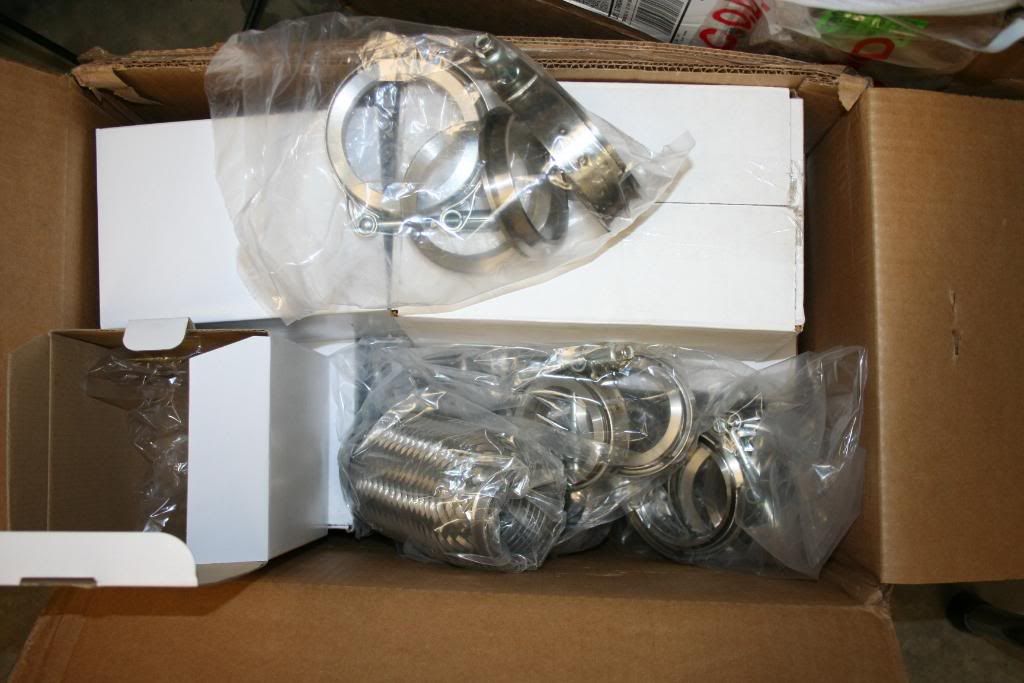
T-bolt clamps anyone:

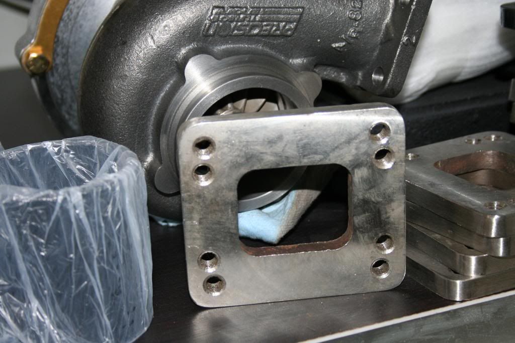
These are the flanges being used on the turbo inlet side. As you can see there are four holes. This means you can bolt up a T3 or a T4 turbo to this setup:
Made 5 sets of IC brackets and scavenge pump brackets. Just have to weld the studs on there and off they go for bead blasting:

I think that is all. Project complete, just have to do the two oil lines.
Also added a breather to the reservoir under the turbo:
I contacted the manufacturer of the Exa scavenge pumps to see if I can reverse the direction. Now, I know with a DC motor it's just a matter of reversing the polarity, and since it is a gear pump it shouldn't be a problem at all. After talking to them, we agreed that it is ok.
Just to make sure, I rigged it up in the garage to a spare battery and some new engine oil. With the polarity reversed it pumps/draws the same as with "suggested" polarity. So I am good to go there. With the pump sitting where it does, this will make the oil line routing a bit simpler.
Turbo intake side of things:
Mase of piping, all in it's place, nice and high:
I had a ton of stuff show up today, enough to do a few more of these:
T-bolt clamps anyone:
These are the flanges being used on the turbo inlet side. As you can see there are four holes. This means you can bolt up a T3 or a T4 turbo to this setup:
Made 5 sets of IC brackets and scavenge pump brackets. Just have to weld the studs on there and off they go for bead blasting:
I think that is all. Project complete, just have to do the two oil lines.
but why wouldnt you position it on its side or on the bottom? even just for aesthetics?
nice clean piping and then that MAF ruining the clean lines. just a suggestion for future builds.
also, whats the breather for again? SP or APS doesnt use one?
nice clean piping and then that MAF ruining the clean lines. just a suggestion for future builds.
also, whats the breather for again? SP or APS doesnt use one?
Last edited by str8dum1; Dec 25, 2009 at 07:28 AM.