When you click on links to various merchants on this site and make a purchase, this can result in this site earning a commission. Affiliate programs and affiliations include, but are not limited to, the eBay Partner Network.
This intake has been one can of worms over the past few weeks. Building the airbox wasnt bad... luckily I had all the material I needed. I didnt have a solid plan on how to mount the airbox to the chassis - just figured there were a handful of OEM threaded bolt/nut locations I could fab up brackets to even if was temporary/short term.
It became apparent that the airbox needed a more solid mounting solution. I added a 3/4" square tube frame structure that mounts direction to the str bumper mounts on the car. It's not where I want it and needs a little touch-up work and quite possibly one more leg added.
Also have some velocity stacks coming for charge pipes ...
not necessarily a merge but separate 3" holes in the side of the box...that needs a little more work and though...I may weld-in the velocity stacks to the box and have couplers connect to the stacks outside of the box. The alternate is to run the 3" pipes through the box, have it seal off some how and use a coupler to connect the stacks. TBD.
I've been caught in light rain showers but I usually don't take the car out if the weather is potentially bad.
Nice turbulent free airflow feeding the turbos, I like it.
Clearance looks pretty tight. Looks like you already cut some holes on the left hand wall. Are they large enough to accept the wide end of the V stacks or just the smaller end?
I don't think you can really go wrong by welding the wide end of the v stacks to the box, in any location possible towards the back of it. The whole box will be pressurized so they will lead the air into the turbo pipes nice and smooth no matter how you slice it.
But if you have the entire V stacks inside the box I believe you would be reducing the effects you're going for by creating turbulence in the box
I needed to cut holes into the box to align it with the IC pipes coming off the blowers...so I will have to trim the stacks (think Venn diagram style). Those holes are 3.5" in diameter - so slightly bigger than the pipes.
My initial thought is to weld them flush within the box - it may be need some alterations.
My next mental exercise is to determine the best place for the pre-turbo water/meth nozzles. Equal distance from each blower in the 3" pipes? a single bigger nozzle mounted on the box? two smaller nozzles mounted on the box? and if they are on the box are should be on the back/slanted side? or the side opposite the stacks(would require some modification to the box)?
As close to the compressors as possible... You don't want ANY condensing pre-turbo. I would think a 90 degree oriented towards nozzle so it goes straight into the turbo compressors (probably industry standard). Just far enough away to let it mix with the air, so it doesn't condense upon compressor wheel contact.
High pressure, low volume for best atomization as you know.
Would be SICK to set some acrylic tubing up for testing with a HD or slow motion camera on it as you drive
Also I heard bad things about using a lot of water. The alcohol will evaporate and not freeze, water not so much.
Definitely post up what you do, but be careful bro...
That video was sick, but it got a little hairy at the end when he let off
I would consider using boost to activate but throttle pedal position to deactivate. I'd have to see the methanol injection setup to see what the easiest way to achieve that would be with some type of module I would guess. Any means 2 achieve shut off simultaneously with blow off valve opening would do. Takes a second for the Boost to Decay when the blow off valve opens so that's a lot of water on the compressor wheel and it might make it fall on its face when you get back on it not sure
By freezing I mean that stuff would literally turn into snow if your intake air temps were cold enoughlol
Could you program an output from your haltech to turn on above a certain throttle pedal voltage?
Not sure if the AEM controller logs errors, it would cause an "open" error temporarily (probably a way to avoid that), but...
Wiring a relay into that output set up to cut power to the solenoid valve(s) below X throttle pedal voltage would cut off the water meth instantly upon releasing the throttle pedal as opposed to waiting for boost to come down in the manifold. (I'm just realizing that referencing post throttle body would make it react pretty quickly, I was thinking pre TB before) BUT it would cut off water a few hundred milliseconds sooner if it referenced the throttle pedal voltage.
Food for thought after you get some videos to examine
I dont know if I can log errors between the AEM and the Haltech. The AEM does output a duty cycle and I can feed that to the haltech and program a user defined table(I believe) ... Cux350z was helping me out with this and I deleted his PM - Cux - if you're reading this will you recap how the AEM & Haltech interact??
The AEM has some built-in error faults so I'm not too entirely worried as I dont intend to tune with the water meth quite yet...I want to get my feet wet and ease in to it.
The velocity stacks came in and they are bigger than I anticipated ... I think I'm gonna have to revise how the two 3" pipes enter the box...
I don't think the AEM and the haltech would be interfacing at all, my concern was tripping that "open" LED that I saw in a photo of the AEM, which would maybe make it not spray, or maybe it would immediately go away when the additional relay closed.
Although it would be nice for the haltech to know that the AEM has a low level error or any other error for that matter to prevent... carnage...
That's neat that it outputs duty cycle. Knowing the duty cycle would probably be adequate depending on how capable the programming interface in the haltech is. In for some info on that one Cux.
James, post up some pics of those things. Any material that can be removed? (I think that's sort of comical lol, sorry though)
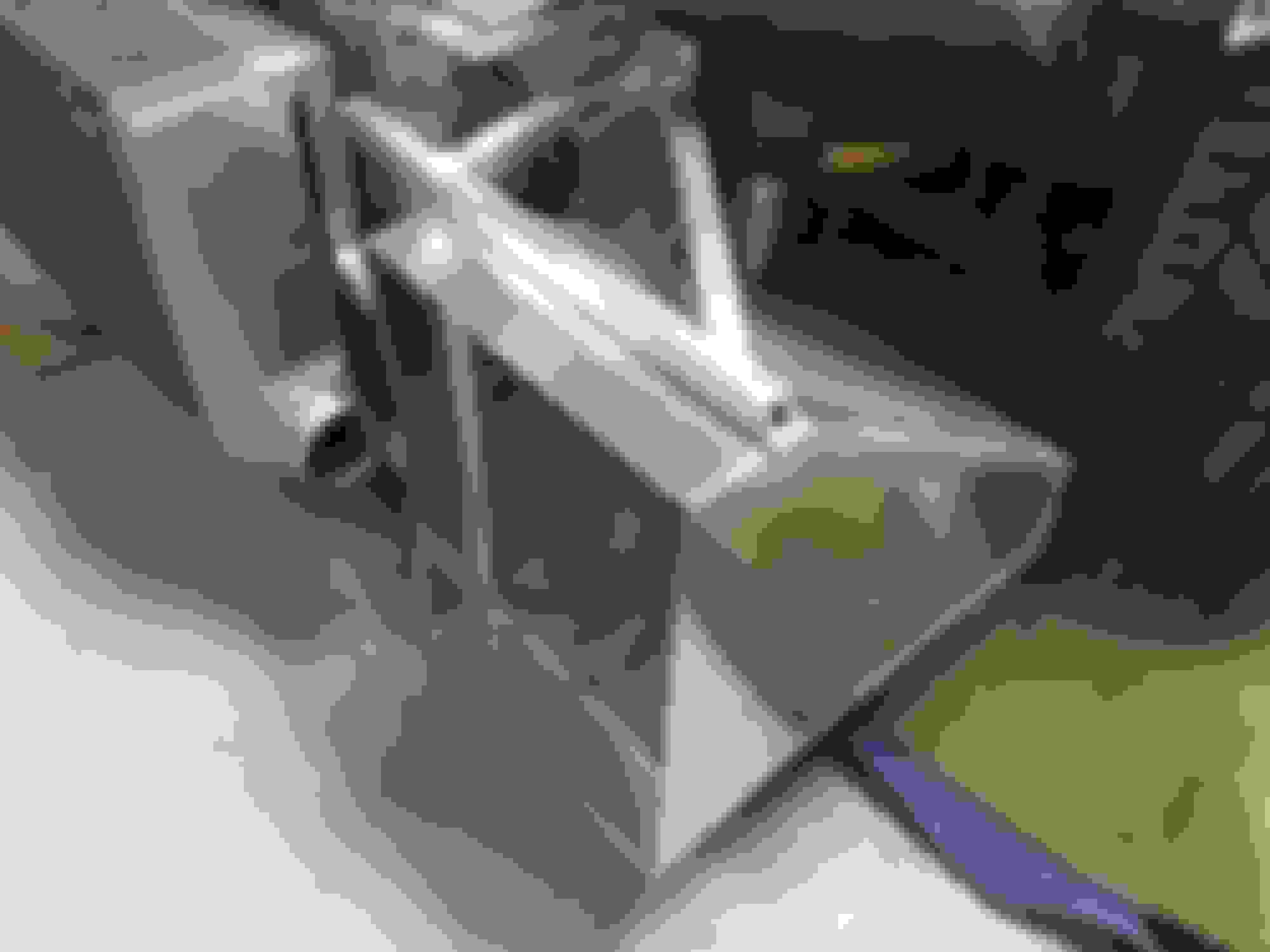
Rewinding a bit...knowing I'd have a few days off in late December/January I decided to knock out the revised radiator & IC mounts out...filled the argon tank and went to town.
With no real plan for the IC I was open minded to solutions ... All I knew was that I wanted it to attach / detach relatively easily and I wanted to keep things modular where I could unbolt them in a few minutes and not hours(which is how the mild-steel rack was).
The angle aluminum was added back in 2012 and I really didnt want to take it off...but decided to mod it a little bit to anchor to. (I'll get some better pics).
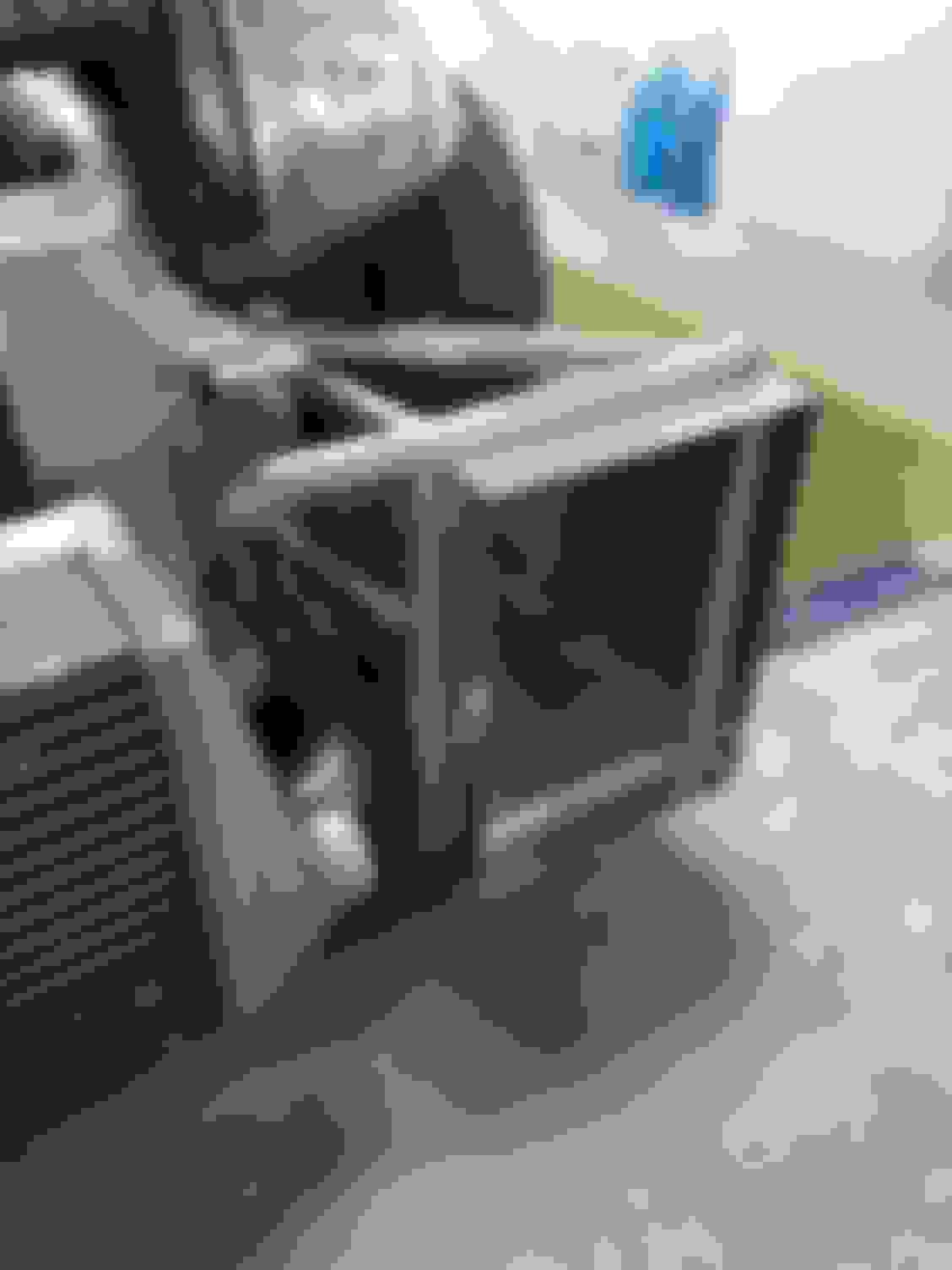
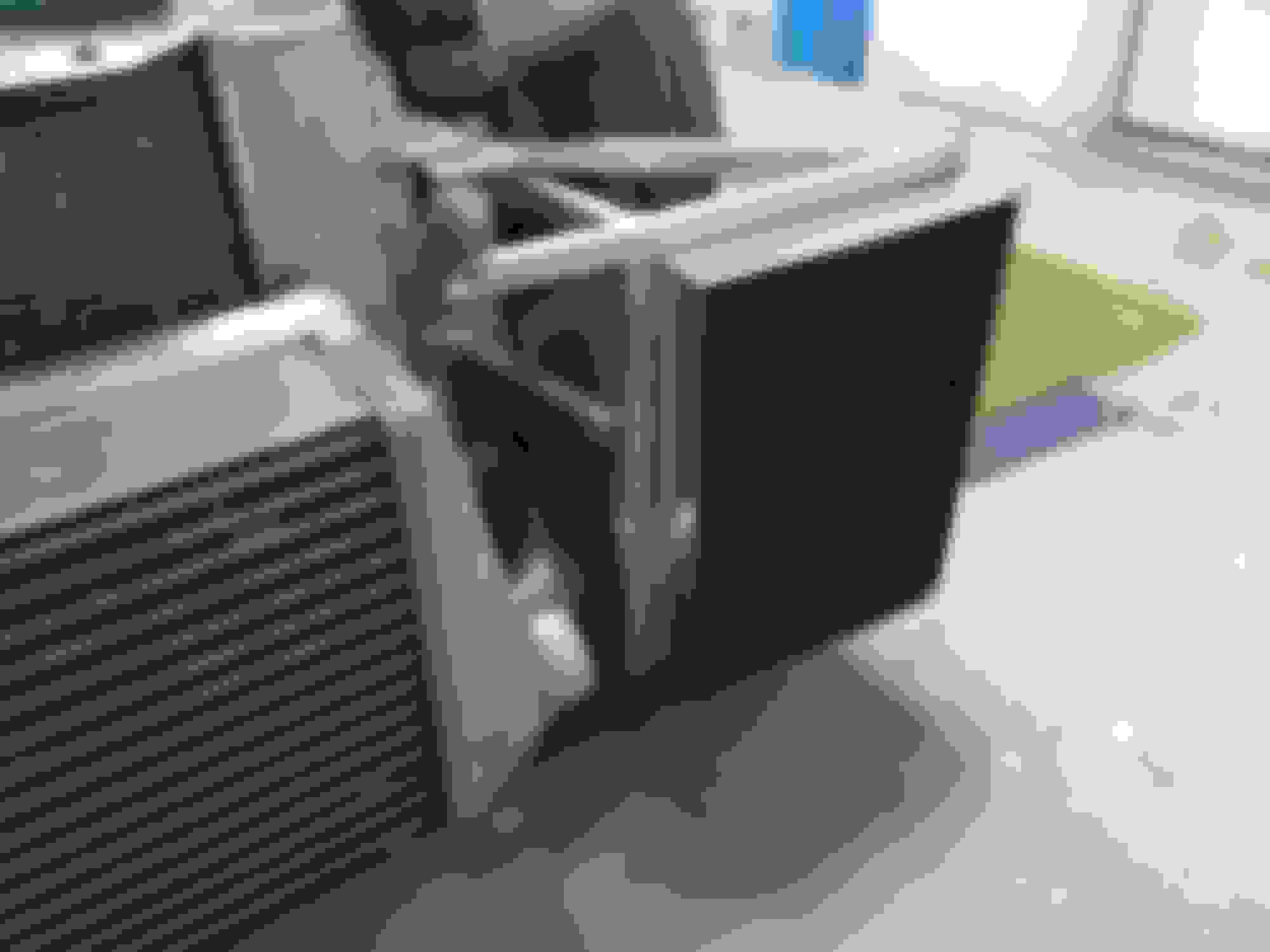
I have a good amount of the 1" tube. I think the 1" square tube is stout enough with a single run on each side but I may add a second tier up the radiator mount points. I was able to hang the radiator off a the drivers side arm without the passenger side welded on. Granted, I put quite a bit of heat into the aluminum.
I'll get some better pics ... it'll all make sense soon.
Yeah, not much on the stacks - prob started as a 1/8" piece of 6061 and I dont know how I'm gonna get them in there - they are way bigger than I anticipated.
I may be able to trim them down. as currently planned they will hit each other and they'll hit the bottom of the air box.


 01-10-2018, 06:45 AM


 !
!