When you click on links to various merchants on this site and make a purchase, this can result in this site earning a commission. Affiliate programs and affiliations include, but are not limited to, the eBay Partner Network.
So this summer I finally got tired of waiting for the Haltech software on my car pc to connect up and display my gauges. So I started designing and building my own Haltech gauge software. Built my own can bus cables as I've got the box and widebands, but no 'expander'. Figured out what they were doing so I can make up any number of ports without one. Hooked up to a box with a canbus adaptor this fall and recorded a quick log of the traffic.
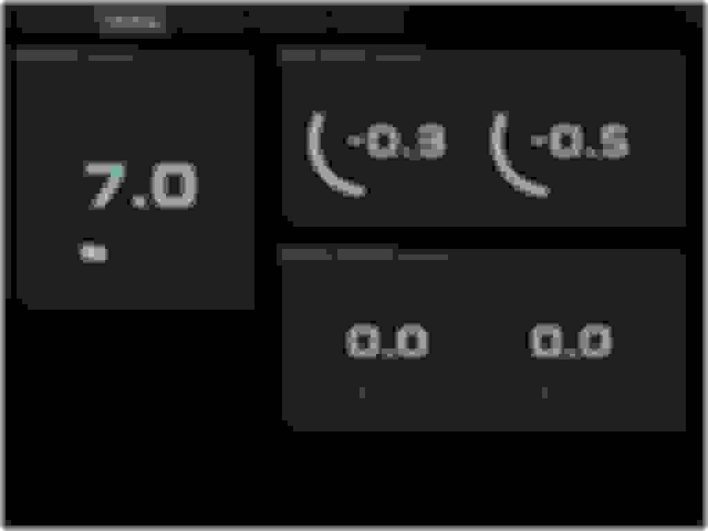
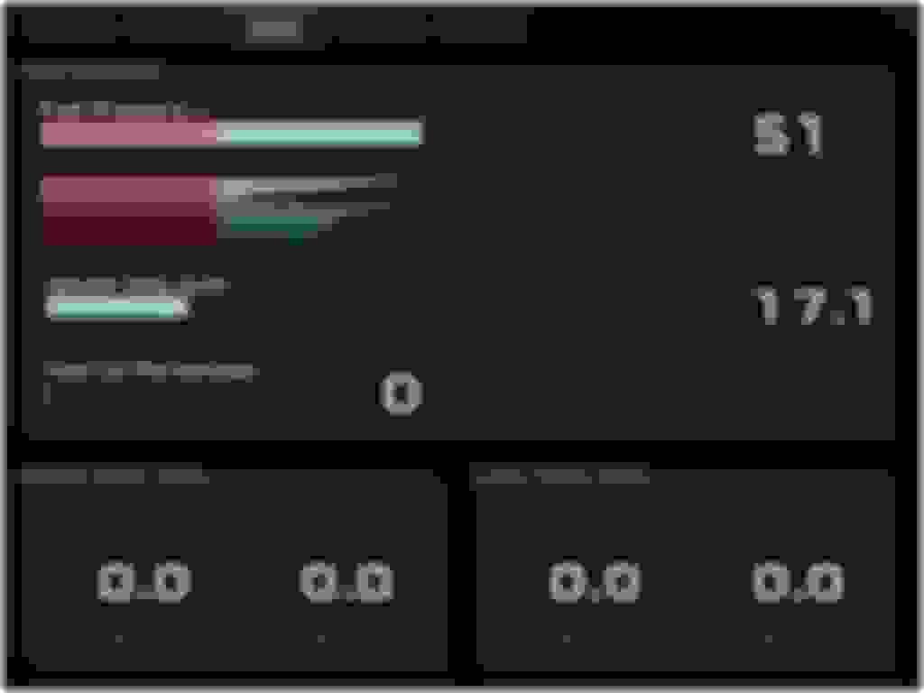
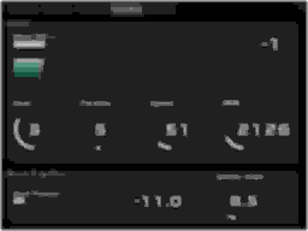
I've been picking away at it while the car is in storage for the winter on my desktop. Got it working to where I'm happy with it, just need to validate full screen operation on the car pc itself with mouse cursor hiding. The res on the 7" touch screen is only 1024x768 so I didn't go crazy trying to make gauges that looked like physical ones, I decided to embrace the screen and go for a boxy easy to read look.
Here's a look:
The section under the boost bar scrolls down to show the recent history. Some of the values have a peak hold feature so I can read that after getting off the throttle. This isn't activated until 75% throttle.
Others like oil pressure have a low pass filter on the indicator and number display to lower the flutter.
My traction maps use the current gear and wheel speed diff front to rear to pull boost and timing to keep the wheel slip in check without slowing down the acceleration more than needed.
Once I get it into the car, I can adjust the color match. The logging records the full data on the can bus for later and auto cleans up files.
The auto dim, uses the sunrise and sunset times to fade the screen down so I'm not lighting up the interior (something I couldn't do before).
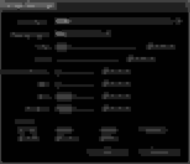
The gauges and tabs can be added/moved and rearranged at will.
The screens installed where the nav would have been (mine didn't have it) and the nav buttons are now a functional keyboard so I've set the software up to use the page up/down or left/right keys to switch tabs, or the left and right 1/4 of the touch screen.
If you can crimp wires to a pin the cables are easy and cheap to make. The connectors/pins are a few bucks on mouser and I just used a ethernet patch cord for the twisted pair wiring.
If you can crimp wires to a pin the cables are easy and cheap to make. The connectors/pins are a few bucks on mouser and I just used a ethernet patch cord for the twisted pair wiring.
Haltech Can connectors are TE Connectivity 1379659-5, pins are 1123343-1.
If there's enough interest, I'm thinking of doing a port to one of my raspberry pie's as a low cost gauge setup (for those that don't have a full windows PC in their car). A few of people up here in the z car club have expressed interest.
this is the best thing to come out the forums in years. We can just act like stance never happened
Originally Posted by bealljk
can we please?
In my (delusional) mind, it never did...I never signed off on that ****
I have to agree, this is some serious and seriously cool shid!! So refreshing to view real innovation and not have to read about people's sorry problems that's Autoshop 101 grade level crap (which is my gripe equivalent to the stance comments, HAR HAR!). And do I worry anyone will be offended? Nope, they won't get this far after going through aarrgghh's original post.
Haltech Can connectors are TE Connectivity 1379659-5, pins are 1123343-1.
If there's enough interest, I'm thinking of doing a port to one of my raspberry pie's as a low cost gauge setup (for those that don't have a full windows PC in their car). A few of people up here in the z car club have expressed interest.
perfect. This will make it much easier than programming for a windows pc environment with so many variables.
I would prefer arduino since that is what I use but it may not have the capabilities.
I have a double din radio with HDMI input. No car PC.
Ok I've had several people interested in a potential product both though PM's and in the local Z club, so I'm going ahead with a Raspberry Pi port so the cost to install can be low.
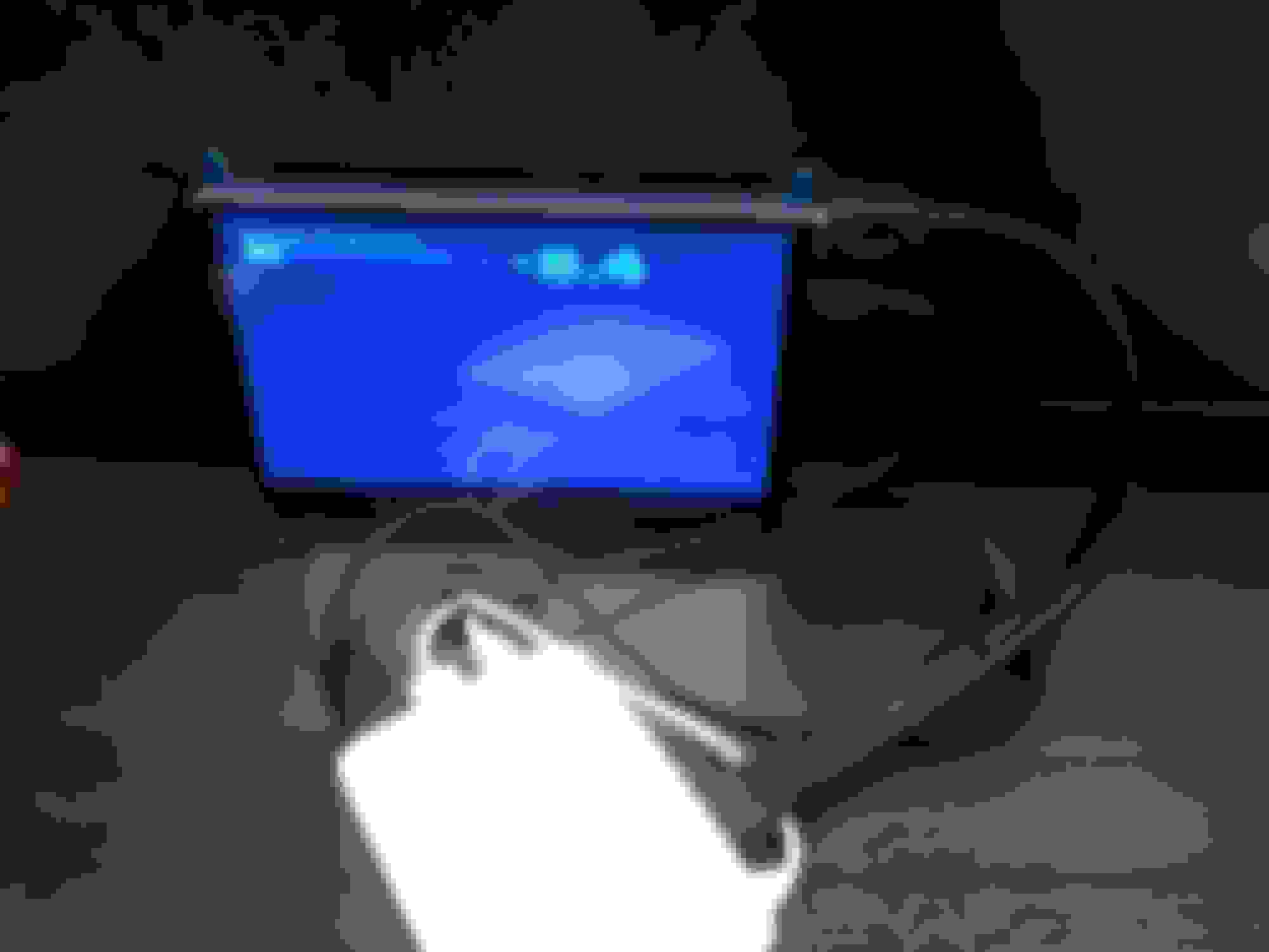
So since then I've upgraded my desktop dev PC, setup a Pi and a Linux box as remote dev targets and started building a full screen GTK app and porting. App runs and I've ported one of the gauge types. Here's the first working gauge:
It's not that blue in person, couldn't get a pic on my phone with the right coloring/lighting without washing out the screen (colors are the same as the above screen shots). For reference the screen is a 7" touch with no case so it can be mounted. Many on Amazon, Pi's in the foreground in the white case.
Still have to port the code for the rest of the gauge drawing, and then port the editor code.
I've also put together a circuit design for a suitable power supply triggered by the accessory power that will turn on the Pi and signal it when ACC is off. It then gives it 60 seconds to shut down before it cuts power. Idle current draw is < 0.5uA, so basically nothing.
Both versions should be available soon. I've almost got the pi version to parity, but I need to remove several hard coded things in both. Currently, that's the location for sunrise/set calculation, the locations of log files, and can communications config. The setup tab, and size of the tabs themselves are currently fixed, targeted at a 1024x768 res.
too late Arrggghhh � jumped to link � can you write the code for the Link G4? thanks, much appreciated!
Had a deeper look at the link. Although there ins't a standard can gauge output format, it can be configured to match the gauge requirements instead. So for the short term, all you'd have to do is setup the can outputs to match the Haltech gauge doc for the values you're displaying.
I'll probably add the ability to specify the data config in a selectable text description file to support just about anything CAN bus.