
Varis/Titek Duct Performance Gains?


Thread Starter
Registered User
Joined: May 2008
Posts: 548
Likes: 2
From: Tulsa, OK
Well, the reason it would take so long is because I would have to do 2 sets of 8 iterations, two minutes each... I guess I was also thinking that it would be better to let the intake air temps increase to high levels again (90-100 deg) before each run (a few more minutes for each iteration); that way, it would be possible to measure and compare the rate of temperature decrease over time at each speed. I mean, I guess I could just take temperature measurements at each speed, but I think it might only get half the picture - the rate of temperature decrease could be pretty important in the case that the nominal difference in final intake temperature isn't too large.
and then repeat all three tests...
i suspect the open bumper test (no flexible tube) and the closed bumper with flexible tube routing air to the hole will be very very similar.
Thread Starter
Registered User
Joined: May 2008
Posts: 548
Likes: 2
From: Tulsa, OK
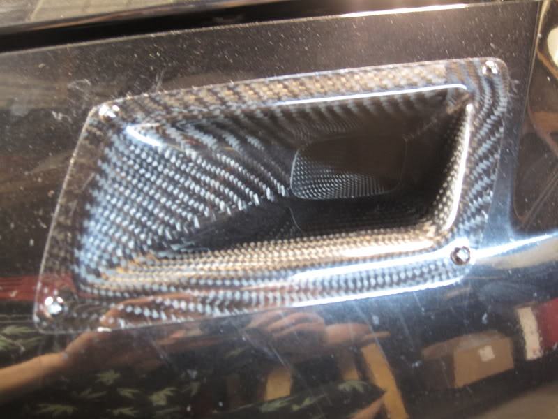
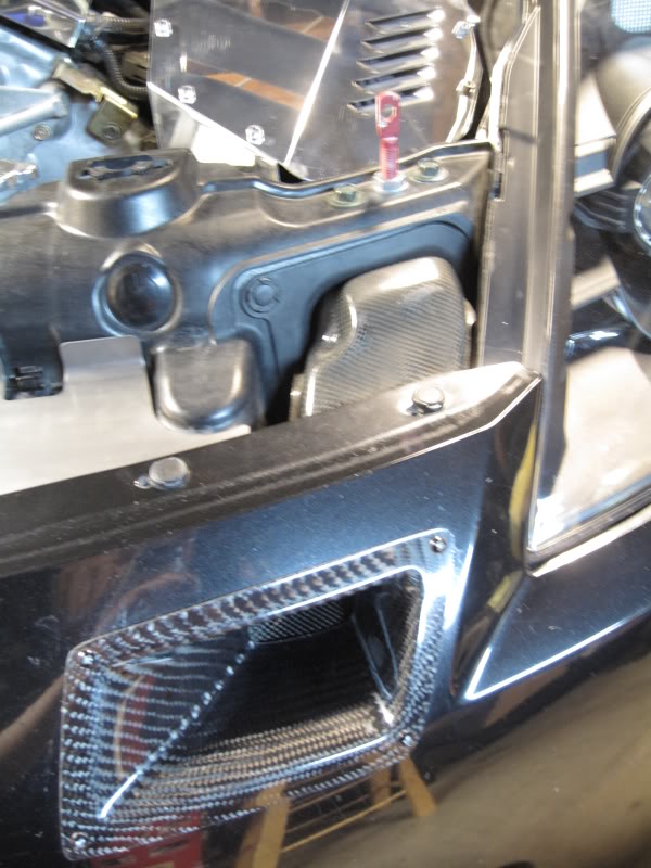
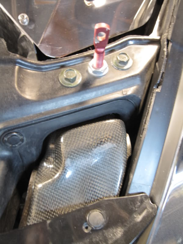
another thing that i am suggesting is adding a flexible tube (think dryer tube ala home depot racing) that is right in the middle of the airstream, near where the OEM tow hook goes, with the other end going up to the hole in the radiator support frame where the intake is, and sealing your bumper hole...
and then repeat all three tests...
i suspect the open bumper test (no flexible tube) and the closed bumper with flexible tube routing air to the hole will be very very similar.
and then repeat all three tests...
i suspect the open bumper test (no flexible tube) and the closed bumper with flexible tube routing air to the hole will be very very similar.


Thread Starter
Registered User
Joined: May 2008
Posts: 548
Likes: 2
From: Tulsa, OK
Thread Starter
Registered User
Joined: May 2008
Posts: 548
Likes: 2
From: Tulsa, OK
UPDATE:
I ran some 3rd gear 25-80mph tests. I'll wait until I complete the other tests before posting the results, but in summary: the average mass flow rate and temperature improvements were there, but were negligible (in the realm of 1%). Average times (assuming I'm using the program correctly to read it) were practically identical.
Just wanted to provide an update. I anticipate sometime next weekend (once I get finished with finals) I'll be able to complete the testing process and provide a full assessment of the situation, complete with colorful charts and graphs.
Thread Starter
Registered User
Joined: May 2008
Posts: 548
Likes: 2
From: Tulsa, OK
My last final is tomorrow morning. Fiancee graduates on Saturday. I should be able to finish testing on Monday, assuming I don't die before then. Sorry this is taking so long.
Finals suck.
Finals suck.

On my OEM bumper setup, I run a Varis air duct teamed up with a C-west CF air duct. My "cold air" setup is connected all the way from the front of the bumper all the way to the intake box. It would be awesome to see your results.
Thread Starter
Registered User
Joined: May 2008
Posts: 548
Likes: 2
From: Tulsa, OK
Okay, it's taken me forever to get a good opportunity with time to spare. I was practically eaten alive by my finals and everything that ensued after that. At any rate, I managed to get a few more tests in, and have decided to stop at this. I'm going to change out my intake (to a K&N drop-in), and I believe that will render any previous tests completely moot if I try to keep testing.
So, I'll start with the very beginning.
0-60 mph Tests
Multiple 0-60mph tests conducted under both "closed" and "open" settings. Specific measurements were taken for mass flow rate and temperature in covered and uncovered settings. Ambient temperature did not fluctuate and tests were alternated to account for any heat soak or other factors.

The uncovered run was 5.19 while the covered run was 5.4. I think the launch on the covered run was worse, though I tried to drop in from 3K rpm each time. (As a side note, I'm thinking that these runs were faster, because a large portion of the data recording has time running, but speed = 0 mph. I'll have to look into this. For the time being, just treat them as 0.2s apart for whatever reason.) This also resulted in the data being somewhat off at the very end on the chart.
Nonetheless, the data shows graphically noticeable decrease in air temperature and increase in mass flow rate. Perhaps this resulted in the 0.2s difference, but it would be unwise to draw that conclusion given the many variables.
I feel dumb because I lost the original Excel data for this test. The graph will have to suffice, but I think it does a solid job of representing the difference, however minimal.
25-80mph Tests
Tests conducted and data averaged. The test was conducted on the same road in 3rd gear at WOT with. Specific measurements taken for mass flow rate and temperature in covered and uncovered settings. Ambient temperature did not fluctuate and tests were alternated.
This data should indicate whether or not there is any substantial "ramming" effect from the duct as well as whether or not it aids in temperature reduction.

The results, along with some further data analysis show a very small increase in average and median mass air flow, in the realm of 0.61% and 0.72%, respectively. Temperature improvements were slightly more impressive, showing a steady drop in temperature while open to a level lower than closed by one degree. Even still, the data is rough, and the gains are minimal.
0mph To Constant 30mph Tests from 100 Deg.
This tests combines the situation of a launch from 0mph w/ high intake temperatures with approximately 1/4 mile of driving at constant speeds.
The problem I encountered here, completely out of my control, was the decrease in ambient air temperature for the "closed" tests. This, logically, would lead to an increased rate of temperature change and a lower minimum intake air temperature for that data. Nonetheless, I went forward with it, because, while I'm willing to do way too much work for this, I have to draw the line somewhere - I'm ready to be done testing this crap.
The ambient temperature, between tests, dropped from 70 degrees to 68 degrees.
Here's the data with intake air temperature over time:

The rate of temperature decrease was practically identical in the beginning, but tapered off for the "open" setting in relation to the "closed" setting. Taking into account the difference in ambient temperatures and the expected effects of that on the rate of decrease, this fell pretty much in line with expectations, assuming no extreme difference due to the duct. As a result, the gains while arguably present at the beginning and at the end, were minimal at best. Again, this is somewhat sketchy data, with more variables than I like. For instance, the rate of acceleration, in preliminary tests, had a distinct affect on the rate of temperature decrease, which left much human error in play. Oh well.
CONCLUSIONS
All in all, I'm glad that I managed to get what testing I have done. I apologize for it taking so long, but I hope it aids anyone asking the same questions I originally asked. I may make this into a separate thread, but I'm not sure if anyone else cares enough about it.
As for the actual gains themselves, there ARE gains from the duct - it is not 100% aesthetic. HOWEVER, those gains, for the most part, are minimal. There is a slight increase in air flow at low speeds, and an even smaller increase at higher speeds. This is likely due to the aerodynamics of the vehicle and redirection of flow over the nose of the car versus straight into it; I imagine that a less aerodynamic car would see larger gains. The rate of temperature decrease was greater by a very, very small margin, and the minimum temperature reached during testing was generally lower by 1-2 degrees.
What this means:
As stated above, the gains are there, but are ultimately negligible. The only testing I did not get to perform was long-term cruising temperature comparisons. I feel the results would be fairly similar - lower by 1-2 degrees. Since 10 degrees lower roughly equals 1% horsepower higher, you're looking at an increase in the realm of 0.2% horsepower at most. For a car putting out 250whp, that's 0.5whp or less.
So if you're considering installing a duct of this type, your reasons should be primarily aesthetic, as the performance gains from this mod are present, but negligible.
So, I'll start with the very beginning.
0-60 mph Tests
Multiple 0-60mph tests conducted under both "closed" and "open" settings. Specific measurements were taken for mass flow rate and temperature in covered and uncovered settings. Ambient temperature did not fluctuate and tests were alternated to account for any heat soak or other factors.
The uncovered run was 5.19 while the covered run was 5.4. I think the launch on the covered run was worse, though I tried to drop in from 3K rpm each time. (As a side note, I'm thinking that these runs were faster, because a large portion of the data recording has time running, but speed = 0 mph. I'll have to look into this. For the time being, just treat them as 0.2s apart for whatever reason.) This also resulted in the data being somewhat off at the very end on the chart.
Nonetheless, the data shows graphically noticeable decrease in air temperature and increase in mass flow rate. Perhaps this resulted in the 0.2s difference, but it would be unwise to draw that conclusion given the many variables.
I feel dumb because I lost the original Excel data for this test. The graph will have to suffice, but I think it does a solid job of representing the difference, however minimal.
25-80mph Tests
Tests conducted and data averaged. The test was conducted on the same road in 3rd gear at WOT with. Specific measurements taken for mass flow rate and temperature in covered and uncovered settings. Ambient temperature did not fluctuate and tests were alternated.
This data should indicate whether or not there is any substantial "ramming" effect from the duct as well as whether or not it aids in temperature reduction.
The results, along with some further data analysis show a very small increase in average and median mass air flow, in the realm of 0.61% and 0.72%, respectively. Temperature improvements were slightly more impressive, showing a steady drop in temperature while open to a level lower than closed by one degree. Even still, the data is rough, and the gains are minimal.
0mph To Constant 30mph Tests from 100 Deg.
This tests combines the situation of a launch from 0mph w/ high intake temperatures with approximately 1/4 mile of driving at constant speeds.
The problem I encountered here, completely out of my control, was the decrease in ambient air temperature for the "closed" tests. This, logically, would lead to an increased rate of temperature change and a lower minimum intake air temperature for that data. Nonetheless, I went forward with it, because, while I'm willing to do way too much work for this, I have to draw the line somewhere - I'm ready to be done testing this crap.
The ambient temperature, between tests, dropped from 70 degrees to 68 degrees.
Here's the data with intake air temperature over time:
The rate of temperature decrease was practically identical in the beginning, but tapered off for the "open" setting in relation to the "closed" setting. Taking into account the difference in ambient temperatures and the expected effects of that on the rate of decrease, this fell pretty much in line with expectations, assuming no extreme difference due to the duct. As a result, the gains while arguably present at the beginning and at the end, were minimal at best. Again, this is somewhat sketchy data, with more variables than I like. For instance, the rate of acceleration, in preliminary tests, had a distinct affect on the rate of temperature decrease, which left much human error in play. Oh well.
CONCLUSIONS
All in all, I'm glad that I managed to get what testing I have done. I apologize for it taking so long, but I hope it aids anyone asking the same questions I originally asked. I may make this into a separate thread, but I'm not sure if anyone else cares enough about it.
As for the actual gains themselves, there ARE gains from the duct - it is not 100% aesthetic. HOWEVER, those gains, for the most part, are minimal. There is a slight increase in air flow at low speeds, and an even smaller increase at higher speeds. This is likely due to the aerodynamics of the vehicle and redirection of flow over the nose of the car versus straight into it; I imagine that a less aerodynamic car would see larger gains. The rate of temperature decrease was greater by a very, very small margin, and the minimum temperature reached during testing was generally lower by 1-2 degrees.
What this means:
As stated above, the gains are there, but are ultimately negligible. The only testing I did not get to perform was long-term cruising temperature comparisons. I feel the results would be fairly similar - lower by 1-2 degrees. Since 10 degrees lower roughly equals 1% horsepower higher, you're looking at an increase in the realm of 0.2% horsepower at most. For a car putting out 250whp, that's 0.5whp or less.
So if you're considering installing a duct of this type, your reasons should be primarily aesthetic, as the performance gains from this mod are present, but negligible.

Great research. Your conclusion is similar to this one
http://www.3_0zmotoring.com/forums/m...hopefully.html
Air scoops: There are lots of people that prefer to go with a scoop that is installed into the bumper itself, such as the varis CF air duct, to help force air into the filter of the intake. I'll use the varis as an example for this. The way the varis intake duct is installed, it is inserted into the bumper at the top front of the bumper. This part of the car if you put it in a wind tunnel is not as effective to allow air to get "rammed" into the scoop as say having the scoop located in the mouth of the bumper. The air hits the front of the car, and then goes up and over the top of the bumper so the effects of any scoop similar to the varis won't be too great or noticeable. Also, without having a fully enclosed airbox for the filter, any air that gets shoved into this duct, will create a current, and much of the air will bypass the filter alltogether. Something like this however WILL help lower intake temps slightly. So there are some benefits of course. and IMO it looks cool
http://www.3_0zmotoring.com/forums/m...hopefully.html

Thread
Thread Starter
Forum
Replies
Last Post
Tochigi_236
Feedback & Suggestions for Our Forum
8
Sep 27, 2015 03:40 PM