
Intake Manifold Runner Clean Up


Thread Starter
Registered User
iTrader: (2)
Joined: May 2012
Posts: 35
Likes: 0
From: Farmington Hills
I was talking with my friend who has owned quite a few LS cars in his day, and now owns an LS2 C6, and he was mentioning that there were some decent gains to be made on the LS2 by cleaning up the intake manifold runners. Basically, where the plastic pieces of the intake manifold are glued/welded together, they didn't do a very good job lining them up, so there are ridges and edges sticking out into the runner. By going in and just cleaning up the ridges and basically smoothing out the wall, he claimed people have seen some really number good increases from this (5-10 whp).
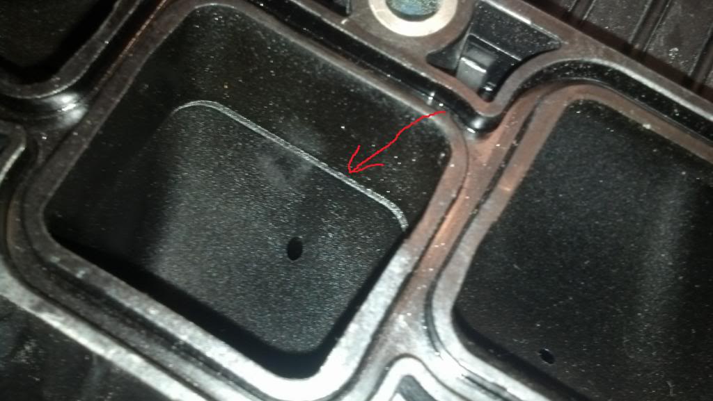
I came home and looked at one of my manifolds, and the HR intake manifolds have the same ridges (see image below). I was wondering if anyone has played around with cleaning up these edges and have some good comparison numbers?
I came home and looked at one of my manifolds, and the HR intake manifolds have the same ridges (see image below). I was wondering if anyone has played around with cleaning up these edges and have some good comparison numbers?

Registered User
Joined: Mar 2013
Posts: 32
Likes: 0
From: Lehigh Valley, PA
I obviously haven't tried it yet but from my reading of other people doing it on a Z32 when i had my Z32, they have made the same claim about grinding down and matching the upper and lower plenums. Same concept me thinks.


Registered User
Joined: Mar 2013
Posts: 32
Likes: 0
From: Lehigh Valley, PA
I have also heard from various people both internet and person who are very car-tech savvy and they say that the manifolds are designed that way to cause the air to, for lack of a better term, swirl and mix better with the fuel. However this is just hear-say, and i have noticed gains from people port matching them.

Registered User
Joined: Mar 2013
Posts: 210
Likes: 1
From: CT and NC
Thread Starter
Registered User
iTrader: (2)
Joined: May 2012
Posts: 35
Likes: 0
From: Farmington Hills
I have also heard from various people both internet and person who are very car-tech savvy and they say that the manifolds are designed that way to cause the air to, for lack of a better term, swirl and mix better with the fuel. However this is just hear-say, and i have noticed gains from people port matching them.
Thread Starter
Registered User
iTrader: (2)
Joined: May 2012
Posts: 35
Likes: 0
From: Farmington Hills
Wow! I hadn't looked at that. I will say, some of the misalignment I have seen with the two pieces of the upper manifold have been rather large. This one is about 1mm, where the largest I would say is 3mm. That misalignment of the upper and lower manifolds looks to be about 2mm per side, which is awful. Thanks for sharing this picture!
Trending Topics
Wow! I hadn't looked at that. I will say, some of the misalignment I have seen with the two pieces of the upper manifold have been rather large. This one is about 1mm, where the largest I would say is 3mm. That misalignment of the upper and lower manifolds looks to be about 2mm per side, which is awful. Thanks for sharing this picture!
keep in mind I looked at both HR and VHR upper / lower intake manifold.
They are all the same. Speaking of the fitting but not the runners lenght or bolt pattern.
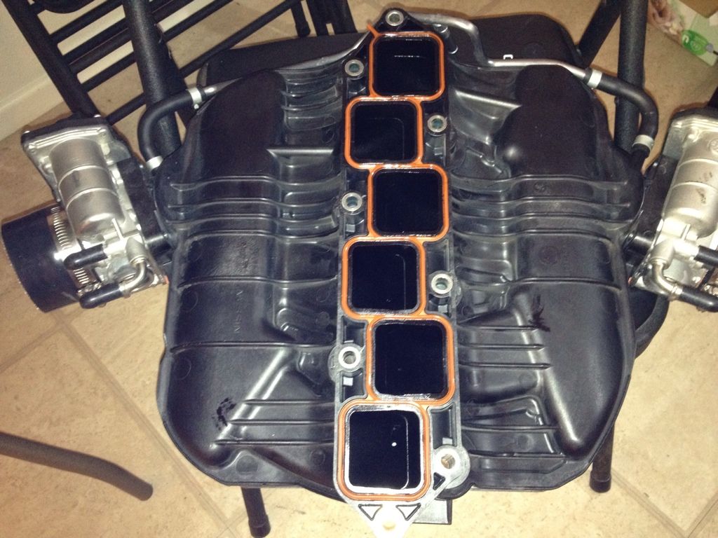
this picture is when I was finish with the matching of the port.


the problem with the HR/VHR is that you cant really do this gasket matched thingy
because the gasket is squares of flexiable rubber.
so the only way is to remove the lower intake manifold and scrach with a small scribber the aera to remove on the intake runner lips with a dremel or something
because the gasket is squares of flexiable rubber.
so the only way is to remove the lower intake manifold and scrach with a small scribber the aera to remove on the intake runner lips with a dremel or something

both pictures I posted is a view from where it would meet the head.
the lower intake manifold is like the cast alluminum and the upper intake manifold is the black looking part ( plastic )
and like I said in my previous post , I used a scriber to scrach on the side where I would need to dremel the side of the plastic port.
it took a couple hours doing it

Thread Starter
Registered User
iTrader: (2)
Joined: May 2012
Posts: 35
Likes: 0
From: Farmington Hills
My original picture was looking into the runner of the upper intake manifold. Nissan injected multiple pieces for the plastic manifold, then glued or plastic welded the pieces together, which is very common practice for plastic manifolds. The problem is the pieces don't fit together very well, so there would be a performance benefit from smoothing out the ports by removing material at the misalignment. I was wondering if anyone had tried it, and how much there was to gain.
Joined: Feb 2008
Posts: 13,406
Likes: 130
From: MexiCali dodging potholes
So I'm attempting this now and it's pretty straight forward on filing and smoothing out the differences...
Who would have the ***** to trim down our stock mainfold
From
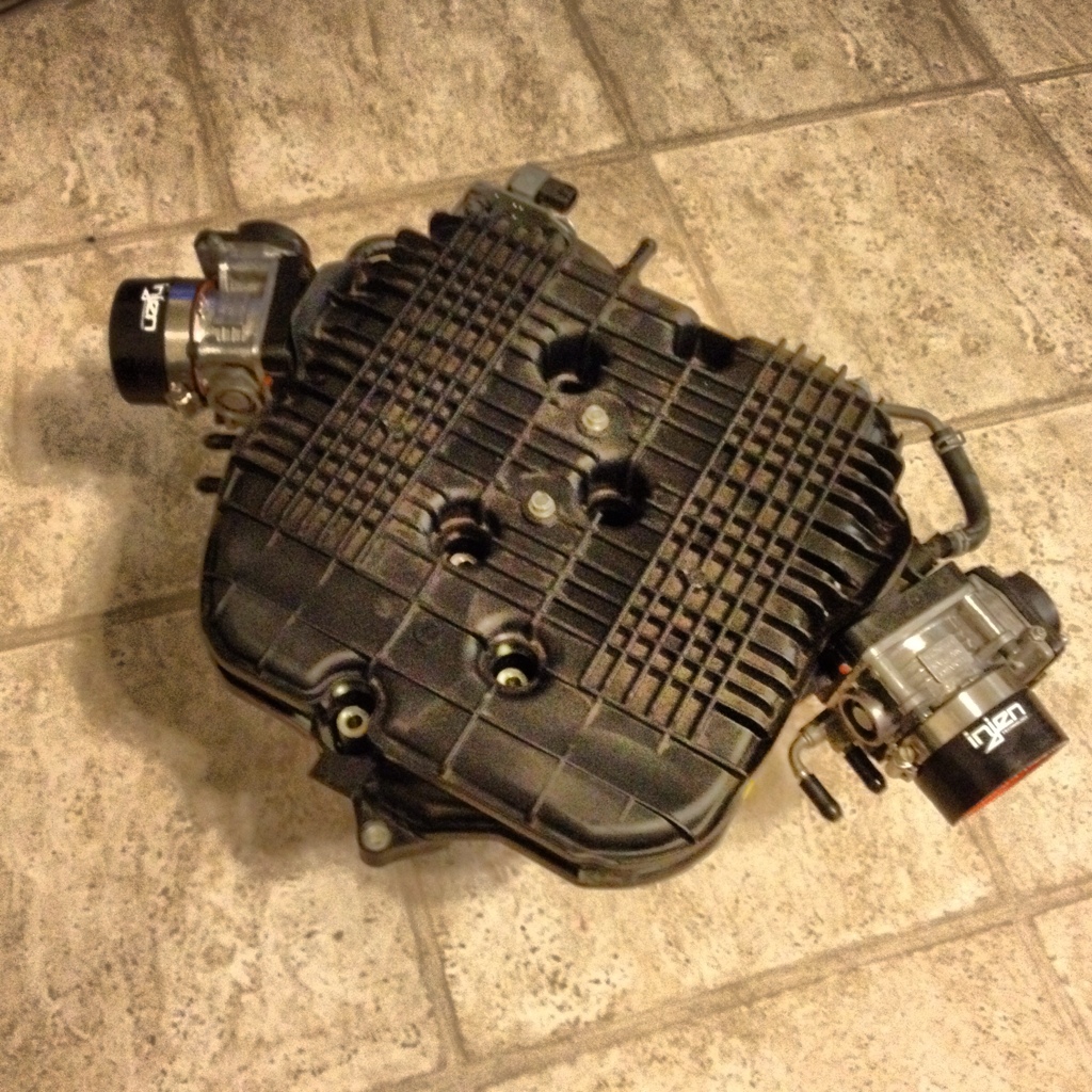
To this

From looking at the bottom, it looks like it can be done?
Who would have the ***** to trim down our stock mainfold
From
To this
From looking at the bottom, it looks like it can be done?
Last edited by KingBaby; Apr 17, 2013 at 03:30 AM.


I know one of the guys from Polk Performance when they were still around back in Arkansas mentioned doing this and finding some gains but I never went through with it. Ill be interested to see what others find out.
Joined: Feb 2008
Posts: 13,406
Likes: 130
From: MexiCali dodging potholes
shoots as a few post above mention. If there is anything to gain it a well worth mod!
Joined: Feb 2008
Posts: 13,406
Likes: 130
From: MexiCali dodging potholes
I'll post pics when I get off work...
Even if this mod only yields 1hp...was easy and worth it to me. Forget what I mention about cutting it up to look like the manifold posted. After looking into the manifold from the TB side it's all one open piece. You CANNOT trim it down.
Even if this mod only yields 1hp...was easy and worth it to me. Forget what I mention about cutting it up to look like the manifold posted. After looking into the manifold from the TB side it's all one open piece. You CANNOT trim it down.

Registered User
Joined: Jan 2008
Posts: 1,580
Likes: 2
From: Tampa, FL
Ive always wanted to somehow split the plastic manifold in half (top and bottom) and add like a half inch of plastic between the two then plastic weld it back together haha.
Then run two 09+ maxima TBs with bigger intake piping (plastic, not metal) going to the stock air boxes with TiTek ram air scoops feeding directly into the air boxes , also my filters would magically disappear at that point. Just for ***** and giggles of course
Then run two 09+ maxima TBs with bigger intake piping (plastic, not metal) going to the stock air boxes with TiTek ram air scoops feeding directly into the air boxes , also my filters would magically disappear at that point. Just for ***** and giggles of course