
Wanted: UpRev Tuning DIY - Tuning 101?
 09-17-2013, 02:46 PM
#281

i�m starting a new tune because i made some mods and my 1 tune isnt perfect.
for my first tune i used only the fuel compensation, but know i whant to tune by MAF first and fuel in the end.
can you give me some advise on this?
 09-17-2013, 04:48 PM
#282

We can't just put it in 3rd at 50mph and shut down at 90mph in 5 seconds.
3rd goes up to 105mph, and starting at 50mph, it takes ~20 seconds. We can't really be discreet, we need a lot more distance. You can probably get 4-5 logs before I'm done finishing a 3rd log, except I'd be in the next town over.
Last edited by T_K; 09-17-2013 at 04:54 PM.
09-17-2013, 06:09 PM
#283

Then use 2nd. Absolute numbers don't matter. You just need to be able to compare runs against each other.
I usually do my runs in 3rd from 1k to 6k which is 80 mph with my stock gearing. I used to do the same when I was NA.
If you are tuning 6k to 7k using some other measure like afr or bfs on the street you still need to get your engine up to those speeds at wot with load so I'm not sure how you are doing that if you are concerned about doing the same to get hp numbers.
Because we aren't boosted and have to cover another 1000rpm.
We can't just put it in 3rd at 50mph and shut down at 90mph in 5 seconds.
3rd goes up to 105mph, and starting at 50mph, it takes ~20 seconds. We can't really be discreet, we need a lot more distance. You can probably get 4-5 logs before I'm done finishing a 3rd log, except I'd be in the next town over.
09-18-2013, 07:27 AM
#284
New Member
iTrader: (5)

Join Date: Jul 2010
Location: FL
Posts: 62
Likes: 0
Received 0 Likes
on
0 Posts
I beg to differ,
on a solid tune when I get a very stable AFR back to back then When I put the new CAM data, the AFR went leaner, meaning it was flowing more air into the engine by the CAMS allowing more air to be sucked up into the engine.
More air but equal fuel as before equal leaner condition.
the power might not be very big but it can defiantly make more power.
this how we tune cams on the street then confirm on the dyno.
not just with seeing AFR change ... MAF voltage and everything as you mentioned.
09-18-2013, 10:31 AM
#285

You're not quite understanding me. "more air but equal fuel as before equal leaner condition" is true, but the point is that in a mass-flow system more air should automatically mean more fuel. This is a fundamental concept of mass-flow fuel injection systems. There is more air, so there is more MAF voltage, so there is more fuel injected, assuming the system is configured correctly. Leaning out is only a side effect if you are not tuned/tuning properly. Increasing airflow into the engine by tuning cams shouldn't affect AFR just like increasing airflow into the engine by increasing the throttle position doesn't.
So knowing the fuel compensation map is all set 100 in every Cell.
the MAF Table has been tuned at WOT from 3000-7500rpm for a very stable AFR pull after pull.
How can you explain that with the new cams degree setup, the system is now leaner ?
you say bad tuning .
but I say the MAF Table was tuned at wot and the AFR for every rpm point was hiting where it was suppose to be.
having the Fuel Comp at 100 in every cell , remove a variable that can affect your result while tuning certain part of the tuning process.
Im not arguing against you but this whole Cam tuning is new to me because I didnt had to deal with that for the pass 3 years on the VVEL engine of the 370z.
anyway after all of those thoughts Im leaving the cams tuning stuff for the dyno. I came up with 2 theory that fight agaisnt each other.
Like now, if its leaner its because the MAF Voltage is like .04 lower at a given RPM point which actualy give less fuel , so less fuel = leaner...
Last edited by XChacalX; 09-18-2013 at 10:36 AM.
09-18-2013, 02:40 PM
#286
So knowing the fuel compensation map is all set 100 in every Cell.
the MAF Table has been tuned at WOT from 3000-7500rpm for a very stable AFR pull after pull.
How can you explain that with the new cams degree setup, the system is now leaner ?
you say bad tuning .
but I say the MAF Table was tuned at wot and the AFR for every rpm point was hiting where it was suppose to be.
having the Fuel Comp at 100 in every cell , remove a variable that can affect your result while tuning certain part of the tuning process.
Im not arguing against you but this whole Cam tuning is new to me because I didnt had to deal with that for the pass 3 years on the VVEL engine of the 370z.
anyway after all of those thoughts Im leaving the cams tuning stuff for the dyno. I came up with 2 theory that fight agaisnt each other.
Like now, if its leaner its because the MAF Voltage is like .04 lower at a given RPM point which actualy give less fuel , so less fuel = leaner...
You're not quite understanding me. "more air but equal fuel as before equal leaner condition" is true, but the point is that in a mass-flow system more air should automatically mean more fuel. This is a fundamental concept of mass-flow fuel injection systems. There is more air, so there is more MAF voltage, so there is more fuel injected, assuming the system is configured correctly. Leaning out is only a side effect if you are not tuned/tuning properly. Increasing airflow into the engine by tuning cams shouldn't affect AFR just like increasing airflow into the engine by increasing the throttle position doesn't.
Consider the case of the steady-state, constant voltage, non-oscillating air flow: at any given time, if we measure the mass of air behind the sensor, we get a fixed value.
Now consider the opposite case of high amplitude oscillation about the same constant voltage as the previous example. The amplitude is high when one cylinder is at peak lift, and weakest during the open-close overlap of two consecutively firing cylinders. The average voltage reading of the MAF is the same in both cases, but if you measure the mass of air behind the sensor during peak lift, there will be more than the constant voltage case.
These are extreme examples, but should be effective to illustrate why the MAF doesn't behave exactly as theory should suggest.
09-26-2013, 09:10 PM
#287

If we assume the MAF is working perfectly under all conditions, and that the air flow across the MAF is absolutely continuous and unidirectional and that it's unaffected by localized pressure waves, then the MAF will only read lower if there's less air coming in, which will affect how much fuel it adds. The end result is that it should never run lean or rich for a given MAF voltage once tuned, regardless of modification as long as we don't mess with the MAF tube. We know that's not true.
This only holds true if airflow is absolutely unidirectional, doesn't oscillate, isn't affected by reflecting pressure waves, and ignore the effects of inertia.
Consider the case of the steady-state, constant voltage, non-oscillating air flow: at any given time, if we measure the mass of air behind the sensor, we get a fixed value.
Now consider the opposite case of high amplitude oscillation about the same constant voltage as the previous example. The amplitude is high when one cylinder is at peak lift, and weakest during the open-close overlap of two consecutively firing cylinders. The average voltage reading of the MAF is the same in both cases, but if you measure the mass of air behind the sensor during peak lift, there will be more than the constant voltage case.
These are extreme examples, but should be effective to illustrate why the MAF doesn't behave exactly as theory should suggest.
Some read....
This is not absolute because engines are very complex but a good general idea of what goes on.
Advance both cams-more low end
Retard both cams- More top end, less bottom end
Advance intake cam- more mid range and maybe less top end, rougher idle and perhaps a little loss right off idle
Retard exhaust cam- engine usualy not to senstive to this, same affect as the latter but to less of a degree. Sometimes useful for matching cam to header and can sometimes see good gains, not usualy though, sometimes a little more top end
Advance exhaust cam- NA engines usualy not too senstive to this except cam matching to header. Idles smoother, sometimes a little more bottom end. Spools turbo faster and for small highly backpressured turbos can help all around power
Advance intake, retard exhaust- Rougher idle, more midrange, broader powerband, slight loss of off idle power, sometimes can gain top end on corked up head engines, more senstive to exhaust backpressure and header design
Retard intake, advance exhaust- smoother idle, narrower powerband, good trick on turbo engines with big cams, especialy small turbos on big engines with a lot of backpressure. Less senstive to intake and exhasut tuning and backpressure
Big turbo systems that run close to crossover can get away with cam timing that works on NA motors- more duration and overlap.
Small turbos with lots of backpressure need less duration and less overlap.
and
Tuning Tips – Camshaft phasing is very difficult to tune accurately without the use of a load-based dyno.
Careful tuning can significantly impact both performance and fuel economy, though the window of
opportunity to do so is very narrow and based on several conditions. This is why it is best tuned using
equipment such as a load-based chassis dyno to help quantify the results.
One method some use to validate their cam phasing tuning is to compare the Mass Air Flow logged when
making cam phasing adjustments. If efficiency is improved, you will normally log a higher Mass Air
Flow value for a given condition (Engine RPM and throttle position). This must then be validated with
the use of a dyno.
Last edited by maxjix; 09-26-2013 at 09:11 PM.
10-10-2013, 09:56 AM
#288
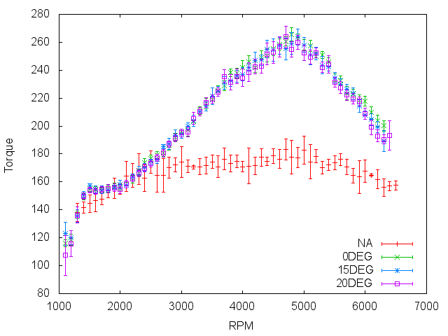
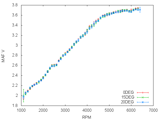
I just finished some testing of intake cam adjustments. I found no benefit to advancing cam timing in the higher load, higher RPM cells. Here are the methods.
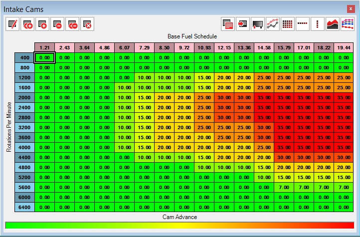
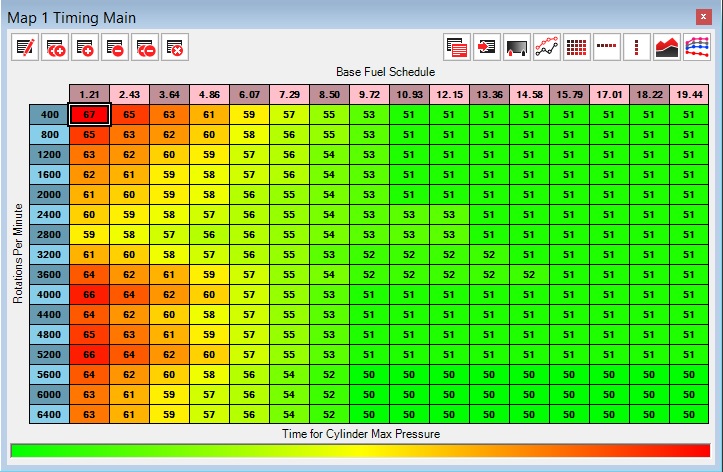
Here is the stock timing table that I used. I'll call it 0DEG.
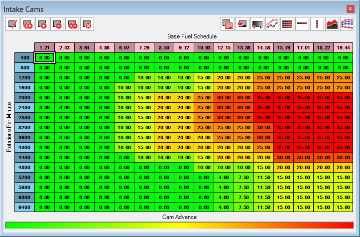
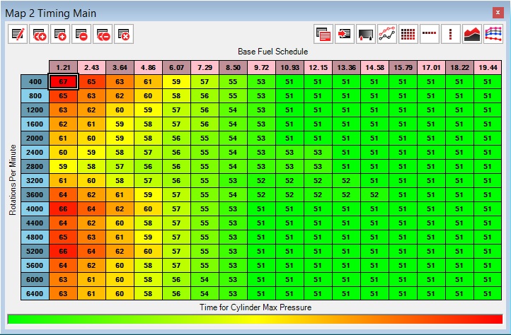
Here is the timing table advanced 15 degrees. I'll call it 15DEG.
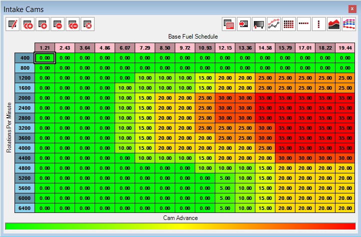
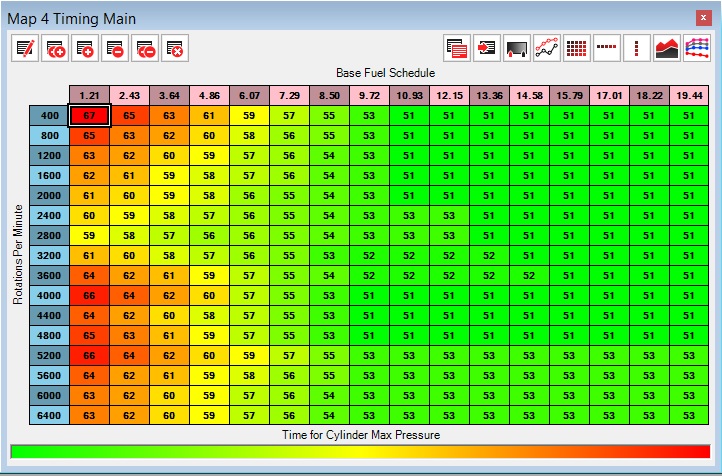
Here is the timing table advanced 20 degrees. I'll call it 20DEG.
0DEG was already loaded on my car. I reset learned fuel trims and then made 4 runs. I then loaded 15DEG and made 4 more passes. I finally loaded 20DEG and made 4 more passes. All passes were made within the same hour to keep atmospheric conditions the same. All passes were done on the same street.
Here's the torque plot. Note that the curves all overlap meaning I found no statistical difference between the different tunes with just 4 passes except for a small blip around 6000 RPM where the 0DEG had a benefit. More passes might have shown a difference. Stock is ploted for reference.
Here's the MAF voltage plot. Again the curves all overlap so there was no change in inflow.
Here is the stock timing table that I used. I'll call it 0DEG.

Here is the timing table advanced 15 degrees. I'll call it 15DEG.

Here is the timing table advanced 20 degrees. I'll call it 20DEG.

0DEG was already loaded on my car. I reset learned fuel trims and then made 4 runs. I then loaded 15DEG and made 4 more passes. I finally loaded 20DEG and made 4 more passes. All passes were made within the same hour to keep atmospheric conditions the same. All passes were done on the same street.
Here's the torque plot. Note that the curves all overlap meaning I found no statistical difference between the different tunes with just 4 passes except for a small blip around 6000 RPM where the 0DEG had a benefit. More passes might have shown a difference. Stock is ploted for reference.

Here's the MAF voltage plot. Again the curves all overlap so there was no change in inflow.
 10-11-2013, 01:32 PM
#289
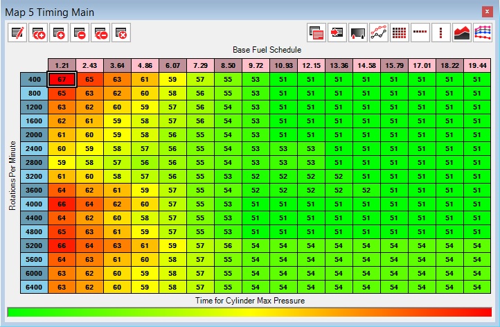
I just did the same sort of testing with ignition timing. I was surprised to see such significant benefits from such small changes. My objective was to flatten my torque curve. Basically what I did to make my test timing tables was to increment the cells in the right lower area by 1 for each map.
Here's the timing table I've been using (50DEG).
Here's 51DEG.
Here's 52DEG.

Here's 53DEG.
Here's 54DEG.
All runs were made within an hour. Ambient temp was 84 deg F, dew point was 68 deg F and baro pressure was 29.89 inches. 4 runs were made for each map. Maps were run sequentially from 50DEG to 54DEG. Knock phones were used. 50DEG, 51DEG and 52DEG had no audible knock. Knock strengths were -1.14 to 0, -0.81 to 0 and -1.7 to 0, respectively. 53DEG had about 2-3 beats of knock heard with the phones around 5500 rpm for each run. Knock strength was -0.57 to 0. 54DEG had an uncountable run of knock heard with the phones around 5k to 6.5k rpm. Knock strength was -2.26 to 0. I had thought that knock strength was a reliable predictor of knock but that does not appear to be the case. Now the results.
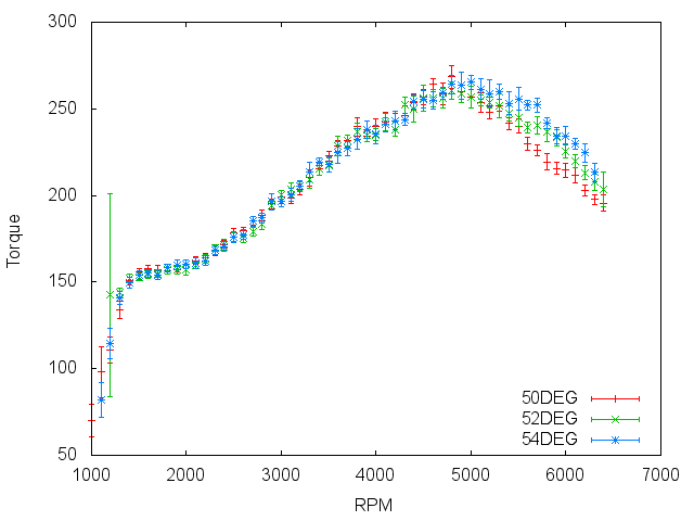
Here's the torque curves which I found very satisfying.
And the hp curves.
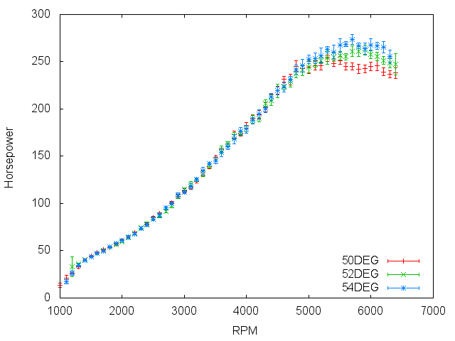
Summary ("error" +/- in parenthesis):
Map=======TQ============HP
50DEG==268(6)@4800====253(3)@5300
51DEG==262(2)@4800====253(4)@5800
52DEG==260(5)@4800====262(5)@5900
53DEG==261(4)@4900====269(3)@5600
54DEG==265(4)@5000====273(5)@5700
Here's the timing table I've been using (50DEG).

Here's 51DEG.

Here's 52DEG.

Here's 53DEG.

Here's 54DEG.

All runs were made within an hour. Ambient temp was 84 deg F, dew point was 68 deg F and baro pressure was 29.89 inches. 4 runs were made for each map. Maps were run sequentially from 50DEG to 54DEG. Knock phones were used. 50DEG, 51DEG and 52DEG had no audible knock. Knock strengths were -1.14 to 0, -0.81 to 0 and -1.7 to 0, respectively. 53DEG had about 2-3 beats of knock heard with the phones around 5500 rpm for each run. Knock strength was -0.57 to 0. 54DEG had an uncountable run of knock heard with the phones around 5k to 6.5k rpm. Knock strength was -2.26 to 0. I had thought that knock strength was a reliable predictor of knock but that does not appear to be the case. Now the results.
Here's the torque curves which I found very satisfying.

And the hp curves.

Summary ("error" +/- in parenthesis):
Map=======TQ============HP
50DEG==268(6)@4800====253(3)@5300
51DEG==262(2)@4800====253(4)@5800
52DEG==260(5)@4800====262(5)@5900
53DEG==261(4)@4900====269(3)@5600
54DEG==265(4)@5000====273(5)@5700
10-16-2013, 05:20 PM
#290
Registered User
iTrader: (8)

Join Date: Jun 2009
Location: Quebec, Canada
Posts: 68
Likes: 0
Received 0 Likes
on
0 Posts
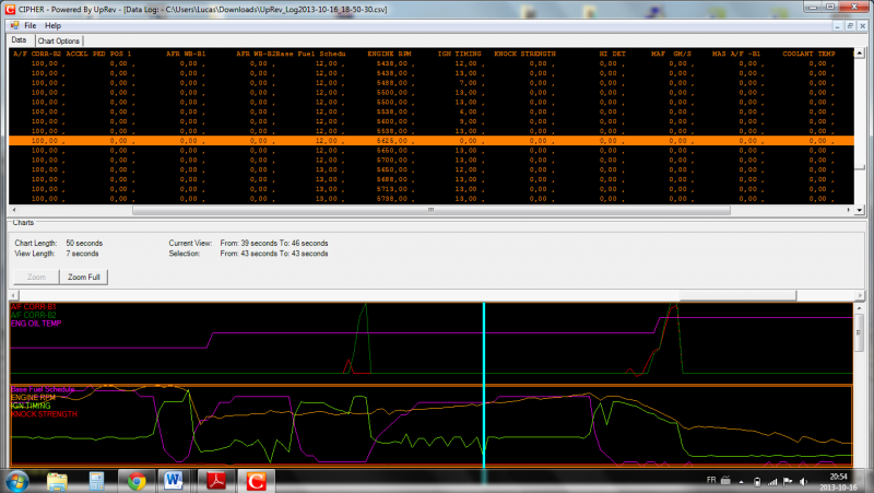
Hi, i have a problem with my timing when i put gas pedal on the floor rapidly...
Timing pass of 13 to 0 deg. and the engine hesitate for few second
I have GT maf and when my BFS hit 13, my maf V is around 4.6V
You can see my timing swing 5-6 times
Timing pass of 13 to 0 deg. and the engine hesitate for few second
I have GT maf and when my BFS hit 13, my maf V is around 4.6V
You can see my timing swing 5-6 times

Last edited by lp_turbo; 10-16-2013 at 05:24 PM.
10-17-2013, 01:59 PM
#292

I had this problem when tuning the fuel on the fueling tables. I started over with the fuel all set to 100's, then proceeded to tune fueling with the MAF table. No problems since, and it is way more responsive too. Another thing that can cause it is if you're too rich. When the OEM W/B bottoms out at 11.25, timing gets all screwy sometimes. But the key is NOT making major changes to the fueling table -- keep it all at 100's +/- 5 -- and also keep your A/F from dipping below 11.5.
Last edited by djamps; 10-17-2013 at 02:02 PM.
10-18-2013, 11:16 AM
#293
Registered User
iTrader: (8)
Join Date: Jun 2009
Location: Quebec, Canada
Posts: 68
Likes: 0
Received 0 Likes
on
0 Posts
You think a wrong tune with K value and maf table can do this?
Because my maf V at idle is near to 1.4V (i think is too high?!?) and full load 4.65V... my oem maf maxed out near to 4.8-5V.
Because my maf V at idle is near to 1.4V (i think is too high?!?) and full load 4.65V... my oem maf maxed out near to 4.8-5V.
10-19-2013, 04:15 PM
#294
Registered User
iTrader: (8)
Join Date: Jun 2009
Location: Quebec, Canada
Posts: 68
Likes: 0
Received 0 Likes
on
0 Posts
I had this problem when tuning the fuel on the fueling tables. I started over with the fuel all set to 100's, then proceeded to tune fueling with the MAF table. No problems since, and it is way more responsive too. Another thing that can cause it is if you're too rich. When the OEM W/B bottoms out at 11.25, timing gets all screwy sometimes. But the key is NOT making major changes to the fueling table -- keep it all at 100's +/- 5 -- and also keep your A/F from dipping below 11.5.
**Djamps** Whats your maf V at wideopen/max load ?
Last edited by lp_turbo; 10-19-2013 at 04:52 PM.
10-19-2013, 07:42 PM
#296
Good to know for oem wideband and 11.5 but I doubt that the oem wideband can do varying the timing because timing swing only at wide open throttle and high boost 15-17psi and the ecm don't check wideband when Wideopen ?!?
**Djamps** Whats your maf V at wideopen/max load ?
**Djamps** Whats your maf V at wideopen/max load ?
Don't tune your fuel on the compensation table... this is meant only for minor corrections. Do your fueling on the MAF table, leave the compensation table all 100's.
 10-21-2013, 09:32 PM
#298
Registered User
iTrader: (8)
Join Date: Jun 2009
Location: Quebec, Canada
Posts: 68
Likes: 0
Received 0 Likes
on
0 Posts
In reading more about it and I saw your maf tool.
If I understand it correctly I need to stays in closed loop and correct my maf table to have about 100 everywhere in fuel comp. table and have my afr target?
I think adjusting the K value to be closer to 1V and 4V and fine tune the maf table it's a good idea?!?
Nice tool btw
Thanks!
If I understand it correctly I need to stays in closed loop and correct my maf table to have about 100 everywhere in fuel comp. table and have my afr target?
I think adjusting the K value to be closer to 1V and 4V and fine tune the maf table it's a good idea?!?
Nice tool btw
Thanks!
10-22-2013, 04:30 AM
#299
Set all cells in fuel comp table to 100. Do not touch K unless you max out a value in your MAF table. Tune the MAF table using WOT data since this is where it matters most. New MAF value is calculated as follows:
aAFR = actual AFR (must be >11.25)
tAFR = target AFR
cMAF = current MAF table value
nMAF = new MAF table value
nMAF = cMAF * (1 + (1/tAFR - 1/aAFR) * aAFR)
aAFR = actual AFR (must be >11.25)
tAFR = target AFR
cMAF = current MAF table value
nMAF = new MAF table value
nMAF = cMAF * (1 + (1/tAFR - 1/aAFR) * aAFR)
In reading more about it and I saw your maf tool.
If I understand it correctly I need to stays in closed loop and correct my maf table to have about 100 everywhere in fuel comp. table and have my afr target?
I think adjusting the K value to be closer to 1V and 4V and fine tune the maf table it's a good idea?!?
Nice tool btw
Thanks!
If I understand it correctly I need to stays in closed loop and correct my maf table to have about 100 everywhere in fuel comp. table and have my afr target?
I think adjusting the K value to be closer to 1V and 4V and fine tune the maf table it's a good idea?!?
Nice tool btw
Thanks!