
Interior LED Conversion


Yeah Ive been looking on how to go about changing the needle color...any thoughts?
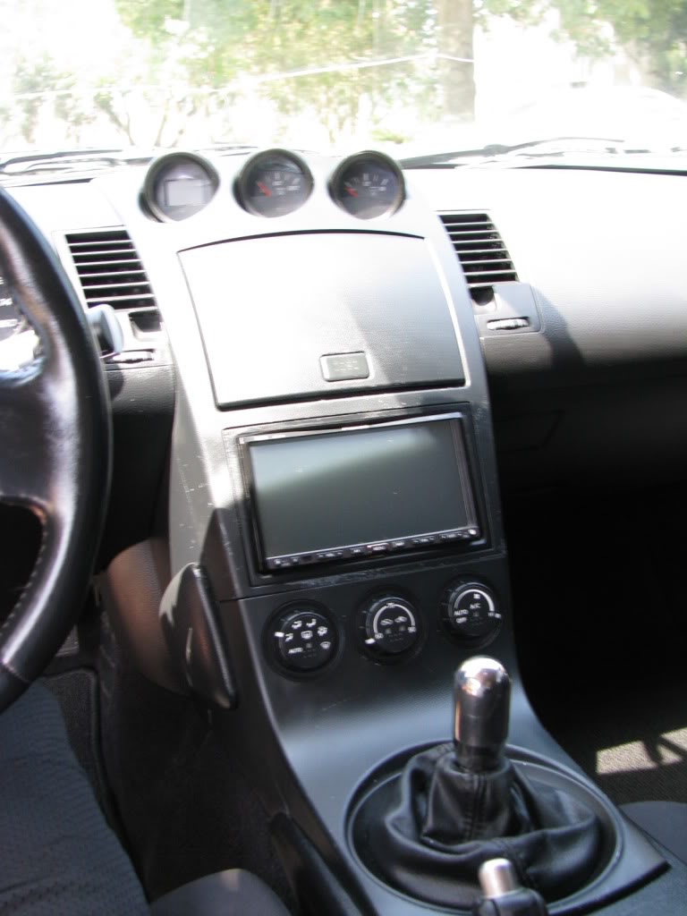
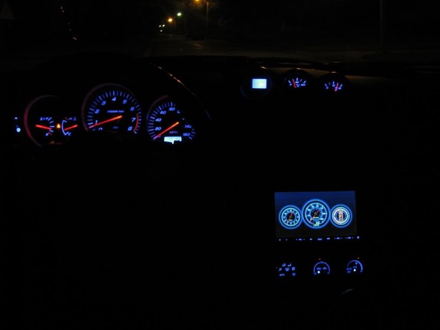
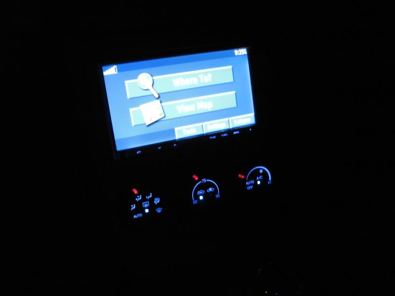
Also tip to anyone doing this.....I painted the inside black plastic peice of the 3 gauge pod center bezel so you dont have those random orange letters saying oil and volts.....stuck out like a sore thumb with all the blue so i painted it all black
Also tip to anyone doing this.....I painted the inside black plastic peice of the 3 gauge pod center bezel so you dont have those random orange letters saying oil and volts.....stuck out like a sore thumb with all the blue so i painted it all black
I have the right angles that i ordered in red to play off the red needles however those things are hard as hell to desolder and solder lol....been prolonging redoing them lol

Nice. You might consider getting a magnifying lamp. I got a small one for $30 or so. Makes working with the small stuff alot easier. On the other hand, you might never use it again unless you do a conversion for someone else....

Just finished this tonight - been quite busy at work so it was spare hours here and there but I'd say it took me ~12 hours. Took it slow and managed not to break any little plastic tabs or anything. Everything came out perfect and it looks awesome - couldn't be happier with the results.
Also did the steering wheel controls, TCS button (has an 0603 in it), the light up ring around the ignition.
Light up ring around the ignition was very easy. Its not an LED but a regular bulb in a small twist socket, so I didn't have anything to replace it with. It has an orange sheath over it that you can remove, revealing a white bulb. I took that off, then cut a piece of an antistatic bag (the silvery ones), and colored said piece with a blue sharpie. The bulb sits in a white plastic housing, and I super glued my piece of blue static paper over where it shines through. Sounds cheap as hell but it looks perfect and took all of 2 minutes.
Only thing left is the pointers on my AC controls...I didn't attempt it. Thinking I might leave the orange LEDs, sand down the orange plastic pieces on the dials and find a way to color them red.
Some pics tomorrow, took some earlier but they were terribad.
Huge thanks to lbz for putting the time in to make the guide, hooking people up with good deals on LEDs, and the patience to answer stupid questions.
Nice timing. I JUST finished doing a single 06 AC controls pointer LED last night. Pics to follow along with the procedure.
I'm pretty sure it will work, I just need to "borrow" an 06 - 08 to test it on. Anyone in LA or OC counties have an 06 - 08 that I could plug it into, I would really appreciate it.
Two of the three ***** on the module were screwed up some during an earlier effort but I can still use them to refine the process.
For now, here's a pic of how the LED that is embedded in the **** is set up. No soldering required inside the ****. The contacts are the little arms on either end of the LED which is a type 0805.
The challenge is dealing with those contacts. If they get too bent out of shape, they won't lay in right and there won't be a good contact. Also, the LED barely lays in the hole. If it's not sitting right, it could go end first into the hole.
I pushed the LED out from the other side using the end of a paper clip. When putting in the replacement LED, I moved the contact arms on the negative end out of the way using the end of an Xacto blade.
Here's a pic of how it looks when first taken apart.
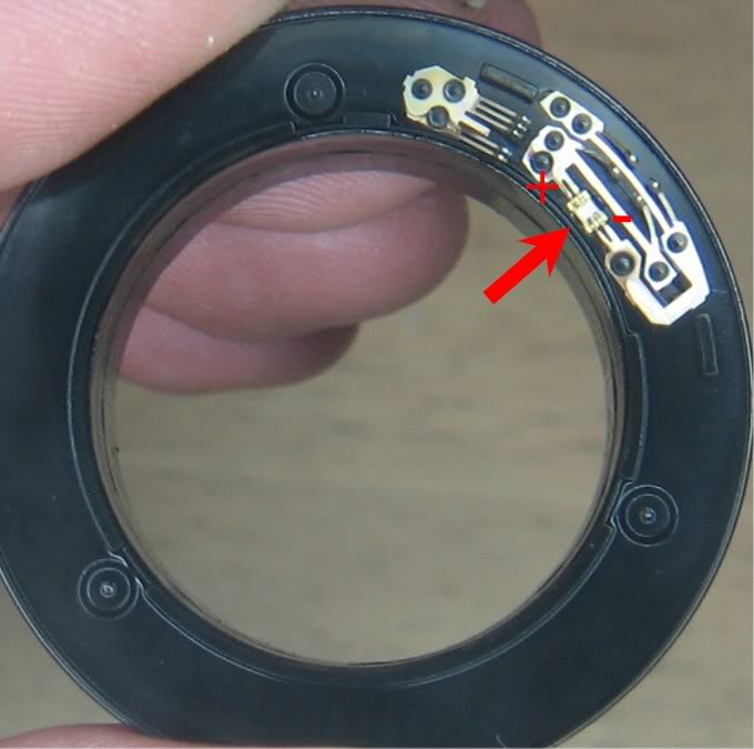
Here's a pic of me putting the new LED into place. You can see one end (positive end in this pic) goes in without having to mess with the contacts on that side. Getting the other end in, under the contacts, I had to bend them up and out of the way (not done yet in this pic). The material is very soft and I figured I only had 1 or 2 shots at it before one or both would fatigue and break.
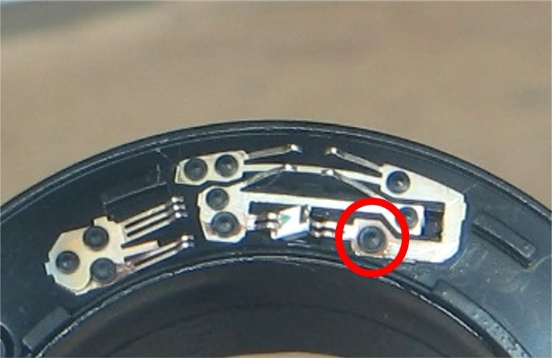
When I try on the ones that got botched, I'm going to see if it's easier to simply shave the melted plastic head off of the negative side contact and lift the entire contact assy out of the way instead of bending anything. After putting the LED in, I would use a bit of super glue on the tip of a sewing needle and glue the contact back into place.
I figure to either shave only the plastic circled in red or also the other one for that contact above it. Whatever allows me to get the LED in without bending the contacts is what I will do.
I'm pretty sure it will work, I just need to "borrow" an 06 - 08 to test it on. Anyone in LA or OC counties have an 06 - 08 that I could plug it into, I would really appreciate it.
Two of the three ***** on the module were screwed up some during an earlier effort but I can still use them to refine the process.
For now, here's a pic of how the LED that is embedded in the **** is set up. No soldering required inside the ****. The contacts are the little arms on either end of the LED which is a type 0805.
The challenge is dealing with those contacts. If they get too bent out of shape, they won't lay in right and there won't be a good contact. Also, the LED barely lays in the hole. If it's not sitting right, it could go end first into the hole.
I pushed the LED out from the other side using the end of a paper clip. When putting in the replacement LED, I moved the contact arms on the negative end out of the way using the end of an Xacto blade.
Here's a pic of how it looks when first taken apart.
Here's a pic of me putting the new LED into place. You can see one end (positive end in this pic) goes in without having to mess with the contacts on that side. Getting the other end in, under the contacts, I had to bend them up and out of the way (not done yet in this pic). The material is very soft and I figured I only had 1 or 2 shots at it before one or both would fatigue and break.
When I try on the ones that got botched, I'm going to see if it's easier to simply shave the melted plastic head off of the negative side contact and lift the entire contact assy out of the way instead of bending anything. After putting the LED in, I would use a bit of super glue on the tip of a sewing needle and glue the contact back into place.
I figure to either shave only the plastic circled in red or also the other one for that contact above it. Whatever allows me to get the LED in without bending the contacts is what I will do.
Last edited by lbz; Oct 2, 2009 at 09:41 PM.
Tested tonight on an 06. The LED lit up but as I turned the **** it cut out in spots. I figure this is due to either the LED not sitting in place exactly right or the contacts not being exactly right or both.
Going to try the alternate method of lifting the entire contact assembly and gluing back in place tomorrow.
Going to try the alternate method of lifting the entire contact assembly and gluing back in place tomorrow.
Update: I realized I can test on my 05. While the controls don't work, the lighting, including the pointer LED, works fine. The one I did earlier, shown above, the pointer LED only lights when I press on the ****. Found out that the LED was not sitting in level.
I bought a used control module off ebay to play with, did the first **** and at first I thought the LED was supposed to snap into the hole but when I did that, the little contact arms did not reach down far enough. I had removed both sets of contacts, put the LED in and then glued the contacts back in place.
Going to try again using the one above since I will not have to deal with the glue situation. I am going to only lift the right contact, as pictured above, slide the LED in under the left contact, drop the right end in place, then glue the contact back down.
Also, I sent an email to black cat custom about creating a set of pieces for in front of the needles / LCD on the center console gauges. The stock pieces in there have amber lettering on them and detracts from the look. I figure he should be able to cut me a set without it being to expensive. I'm suggesting that he include those either with lettering or without in future kits. I think it would really help finish out the look of a conversion.
Last edited by lbz; Oct 11, 2009 at 03:20 PM.

Here is what I did:
I used a 603 style led and dropped it down the "hole". This way I didnt have to bend the little leads. I also tinned the leads of the led with a small amount of solder so that when it sat on the leads i could apply a little heat and they would attach themselves. A word of warning though this way will take a lot of time unless you figure out a good way of getting these leds down the hole. They have to be oriented correctly and that can take quite a bit of time. Anyway good luck with the project!
I used a 603 style led and dropped it down the "hole". This way I didnt have to bend the little leads. I also tinned the leads of the led with a small amount of solder so that when it sat on the leads i could apply a little heat and they would attach themselves. A word of warning though this way will take a lot of time unless you figure out a good way of getting these leds down the hole. They have to be oriented correctly and that can take quite a bit of time. Anyway good luck with the project!
^ Thanks for the tip. I confirmed that I was shoving the 0805 type LED too far down into the hole. It doesnt have to "click" in like I thought. I was able to correctly position a red 0805 tonight but the little contact arms were tough to work with. I took one side of contacts off, put in the LED, then glued the contacts back into place.
I got the little arms to stay permanently touching the LED contacts but for some reason, when I put everyting back together, the LED does not stay lit at the 10 oclock, 12 oclock, 1 oclock and 2 oclock positions.
If I press on the dial, like to turn it, it lights up, or if I turn it to the positions near either end, it lights up and stays lit.
I'm going to take the switch apart again tomorrow, see if I can figure it out. I assume that I may not have the assembly re-built tighly enough but I double checked those fingers on the metal retainer, everything in place, made sure the two legs that solder in are good and tight in the board, the switch is level relative to the board. Just cant' figure out why it cuts out in the center....
Figured out the amber coating on the 06 - 08 AC Controls pointers. No sanding or grinding required. The more I looked at it, the more it looked like a flexible coating and sure it enough, once I dug at the edge a bit with an Xacto blade, it opened right up. When I got this much of it up, I just peeled the rest off.
Some scraping was required on the lower end, I think maybe a spot of adhesive was used there, and some scraping on the underside but that only took a few minutes.
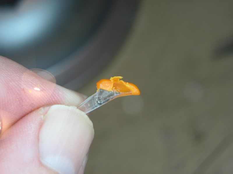
Here's a pic of it lit up with a red LED.

The downside is that the pointer will be clear / nuetral instead of amber in the daylight. I guess if someone really had to have a colored pointer, they could look into a coating that would work. Not sure if the coating used at the factory has specific luminance properties or not.
Also, maybe not really a down side, but the pointer itself does not stick out from the surface of the dial like it used to. The amber coating is thick enough to cause it to be more of a bump on the surface of the dial. Without it, that bump is reduced by half roughly, just barely higher than flush.
NOW I can finish this section of the procedure. I have a fresh unit from E-Bay to play with and will post what I figure out the steps for best results.
Some scraping was required on the lower end, I think maybe a spot of adhesive was used there, and some scraping on the underside but that only took a few minutes.
Here's a pic of it lit up with a red LED.
The downside is that the pointer will be clear / nuetral instead of amber in the daylight. I guess if someone really had to have a colored pointer, they could look into a coating that would work. Not sure if the coating used at the factory has specific luminance properties or not.
Also, maybe not really a down side, but the pointer itself does not stick out from the surface of the dial like it used to. The amber coating is thick enough to cause it to be more of a bump on the surface of the dial. Without it, that bump is reduced by half roughly, just barely higher than flush.
NOW I can finish this section of the procedure. I have a fresh unit from E-Bay to play with and will post what I figure out the steps for best results.
Last edited by lbz; Oct 18, 2009 at 08:04 PM.
Discovered that I probably misunderstood one of Acree's posts about resistors. Found out recently that changing the resistors can increase the brightness. I just ordered 500 (minimum I could order) of each value needed for the AC and door mounted controls as well as what I think will work for the odometer and the silver buttons on the sides of the main cluster.
I think the odometer would only be an issue when the LCD polarity is reversed as that is pretty hard to see during the daylight.
Anyway, will probably take 1 - 2 weeks to get the resistors in and when I get them I will be experimenting and posting the results.
I think the odometer would only be an issue when the LCD polarity is reversed as that is pretty hard to see during the daylight.
Anyway, will probably take 1 - 2 weeks to get the resistors in and when I get them I will be experimenting and posting the results.


Registered User
Joined: Nov 2008
Posts: 40
Likes: 0
From: PA
I changed the resistors on the triple gauges and it did not change the brightness at all. Maybe I had to change all the resistors in both the tripple gauge and the main gauge cluster for it to work or try different LEDs. In any case, I like everything you have done so far and if the resistor change does work I will definately do it. Let me know. PM me with a price for the reversal film for the odometer LCD please.
PM sent. I went back and reviewed Acree's thread and he posted that changing the resistors on the triple gauge had no effect.
He did say that changing the resistors on the doors and the AC controls had an effect and someone else told me about changing the ones on the main cluster board.
I have found the ones involved with the silver side button lighting and will be changing those as they are a bit weak.
The main thing, besides the odometer, that I'm looking for out of this is improving the AC dial pointers. I noticed on my 05, they are clear but there is a coating of white involved. I'm going to scrape that off a spare that I have and see if it helps.
PM sent.
I went back to Acree's thread on this. He posted that changing the resistors on the triple gauge had no effect. I think that's where I mis-interpreted that to mean the entire system.
He has a post where he lists (with pics) the resistor package types, values and quantities involved with changing the door and AC controls but nothing else. He even makes a correction on the value of a door resistor saying the first value was too low and over drove the LED causing it to burn out.
Here's a link to that thread. https://my350z.com/forum/exterior-an...inished-4.html
My main intent other than the odometer issue is the AC dial pointers. Even as red, which is hotter than blue, they are kinda week. The actual plastic pointer piece is clear but it has a coating of white. I have a spare set of controls so I'm going to scrape the white off one of those and compare it against stock and see if that makes any difference.
I've located the resistors that control the silver side buttons on the main cluster and I'm pretty sure I got a handle on the LCD ones.
Once I have it nailed down I will update the applicable sections in this thread as well as the PDF of the whole procedure.

Couldn't you use a bright led and just paint the tip with a transparent paint. It'd be just like the stock orange that you peeled off? Just the first thought I had when you were talking about this problem.
My first approach will be to replace the resistors and I'm not sure if I will like the painted red pointers in daylight but still, good idea to experiment with.
I have used the transparent paint in the past with really good results, but that was in my old 240sx. If I can ever get around to this project I will try spraying each with some blue transparent paint to see what results I get but it'll prolly be a while before I can get around to it. How hard is it to remove the small amber pieces. If its not too bad I may try it with the stock led's just to see what it would look like....