
Interior LED Conversion


I will sometime in the near future. lbz is sending me some of his left over strips to try out on an extra triple gauge lcd that I have. Will post side by side pictures when completed.
Last edited by brettrr; Jul 29, 2009 at 12:34 PM.

Section 7 - Rocker Switches
Read this procedure through before you get started. This procedure assumes the seat control rocker switches have already been removed from the car.
Pictures of how to remove the rocker switches are not provided but will be added at the first opportunity.
NOTE: WORK ON ONLY ONE SWITCH AT A TIME. This gives you a reference switch if something goes wrong with the one you are working on.
Turn the switch upside down so that the 4 contacts are to your right.
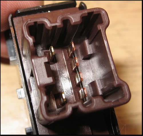
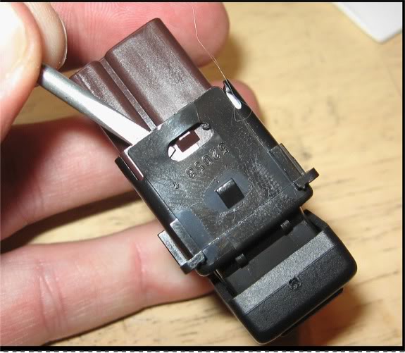
Use a small flat blade screwdriver to pry the ends loose / over the notches. Be careful you don't crack the housing. You don't have to pry too hard. Also, you may have to go back and forth a bit to get both sides over the notches, one side will typically want to snap back into place as you work the other side. Don't hurry this.
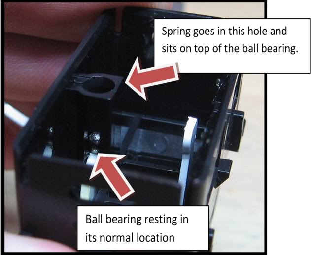
Carefully pull the inside of the switch up and out of the housing. Leave the housing upside down. There is a spring, sitting on top of a bearing, on the left side. If you turn the housing over, the spring and the bearing can fall out. If the bearing rolls away and gets lost, the switch will be ruined.
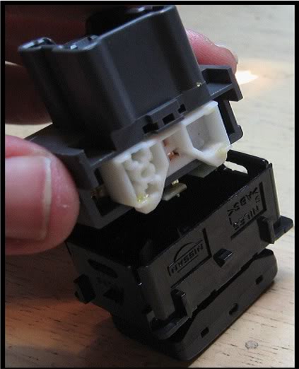
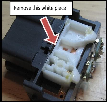
Remove the white piece and place it face down, with the contacts facing up. Do not clean off any of the lubricant off of either surface.
Stand the switch up so that the LEDs are facing up and remove and replace the two LEDs. The cathode end on the larger PLCC-2 LED is facing the right side edge while the cathode for the smaller 0805 is facing towards the left. (Sorry about the poor focus)

Re-insert the white sliding contact piece
In the housing, make sure the ball bearing is resting in the depression in the middle of the base of the white lever / actuator.
Carefully lower the switch piece into the housing and then snap them together.
Repeat the process for the other switch
Read this procedure through before you get started. This procedure assumes the seat control rocker switches have already been removed from the car.
Pictures of how to remove the rocker switches are not provided but will be added at the first opportunity.
NOTE: WORK ON ONLY ONE SWITCH AT A TIME. This gives you a reference switch if something goes wrong with the one you are working on.
Turn the switch upside down so that the 4 contacts are to your right.
Use a small flat blade screwdriver to pry the ends loose / over the notches. Be careful you don't crack the housing. You don't have to pry too hard. Also, you may have to go back and forth a bit to get both sides over the notches, one side will typically want to snap back into place as you work the other side. Don't hurry this.
Carefully pull the inside of the switch up and out of the housing. Leave the housing upside down. There is a spring, sitting on top of a bearing, on the left side. If you turn the housing over, the spring and the bearing can fall out. If the bearing rolls away and gets lost, the switch will be ruined.
Remove the white piece and place it face down, with the contacts facing up. Do not clean off any of the lubricant off of either surface.
Stand the switch up so that the LEDs are facing up and remove and replace the two LEDs. The cathode end on the larger PLCC-2 LED is facing the right side edge while the cathode for the smaller 0805 is facing towards the left. (Sorry about the poor focus)
Re-insert the white sliding contact piece
In the housing, make sure the ball bearing is resting in the depression in the middle of the base of the white lever / actuator.
Carefully lower the switch piece into the housing and then snap them together.
Repeat the process for the other switch
Last edited by lbz; Aug 1, 2009 at 10:06 AM.

Sorry about that, I must have lost track. I just PM'd you, please send me your email address via PM and I will send it today.
Last edited by lbz; Aug 4, 2009 at 03:50 PM.


Section 8
2006 – 2008 Cup Holder LEDs
This section only applies to 2006 – 2008 model years and describes how to convert the LED lighting for the built in cup holders.
Thanks to forum member eodnhoj for the pictures and the chance to document this.
Items you will need:
* Three 8mm T1 style LEDs with the resistors built in. You can often find these at auto parts stores like Pep Boys or on E-Bay.
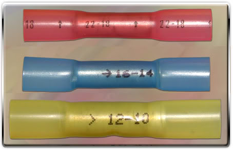
* Crimp butt connectors (see picture below) or heat shrink connectors. I don’t know
the gauge of the wire; it looks to be in the 22 gauge range or possibly higher so look for butt connectors in that range.
* Another option is to plan on soldering the spliced wires together and covering with electrical tape or heat shrink. If you don’t have soldering equipment or skills, the butt connectors should work fine.
* You should have a glue gun handy or some other type of adhesive that you will use to secure the new LEDs in place. “GOOP” brand automotive adhesive would work well in this situation but a glue gun will work best.
* Zip ties will come in handy to wrap up any slack wiring from your new LED. These often come with approximately 3 feet of wiring, most of which is not needed.
* A flat blade screw driver
* A Phillips head screw driver
* A socket wrench with a 6” extension and a 10 mm socket
Heres a pic of butt crimp connectors
- Use the procedure in Section 2A to remove the lower finisher.
- Remove the two screws, small fasteners and “L” brackets from the very front of the horizontal center console
- Remove the two screws, one on each side, at the very back of the horizontal center console.
- Lift the emergency brake handle as high as it will go
- Pull the horizontal center console up from either end to get your hand underneath and disconnect the wiring connector for the LED
- Remove the horizontal center console by sliding it up and over the emergency brake handle. You may have to exert more than the usual force on the handle to get it high enough for the hole in the center console to clear the end of the handle
- One the center console is out, turn it over and you will see the wiring connector and the LED housing.
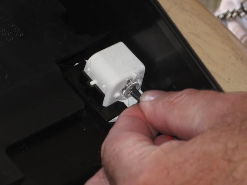
- Twist the LED assembly and pull it out of the housing.
- Leaving 4 or 5 inches of factory wiring coming out of the connector, cut the wires and set your stock LED assembly off to the side. You may wish to keep it if you plan on restoring your car to totally stock in the future.
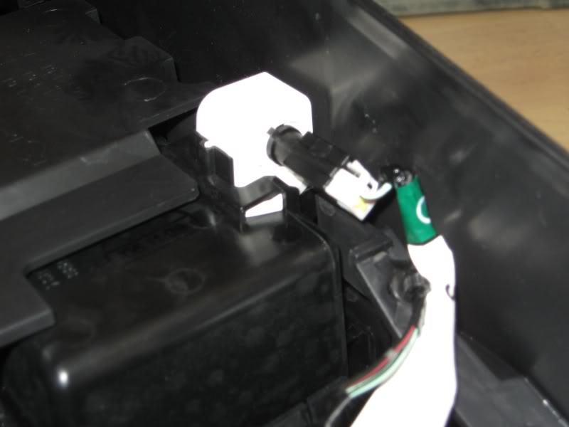
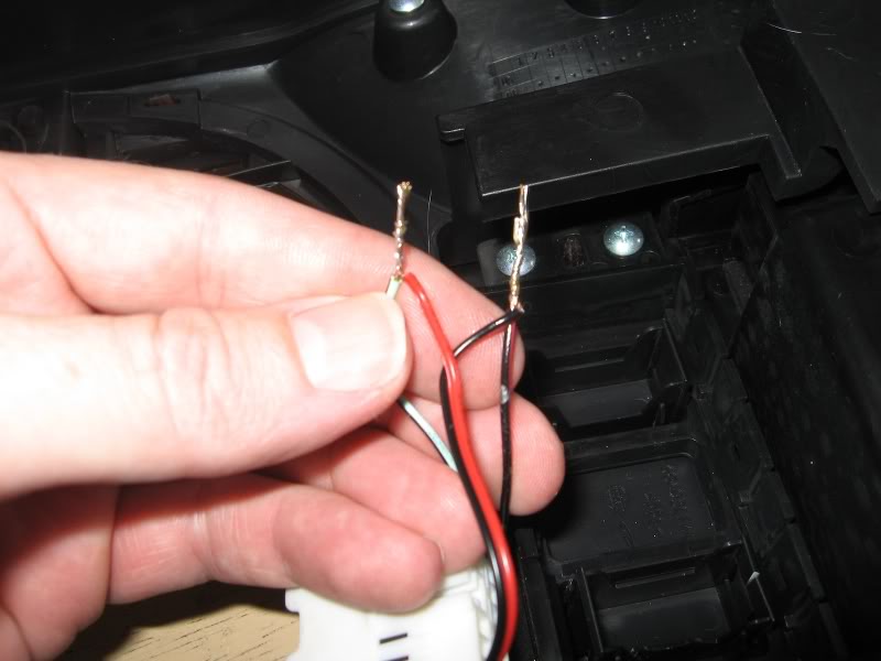
- Splice in the two leads from your new LED. The green lead on the connector is the positive lead and the black lead is ground. On most LEDs that have been pre-wired, the red lead will be positive and the black will be ground. Your completed splice should look similar to that pictured below.
- The picture below shows the leads twisted together and soldered. If you are not soldering, put one end of each pair into a butt connector, crimp the connector with some vise grips, pliers or channel locks and then wrap it with electrical tape.
- Insert the new LED into the hole in the housing. With the 8mm size LEDs, the base of the LED bulb is barely larger than the hole and should stop from going all the way through.
- Hold the base of the LED against the outside of the housing and glue it in place using the glue gun.
- Clean up any excess / slack wiring with zip ties
- Re-install the center console; be sure to reconnect the wiring connector before fastening the console in place with the screws.
- Re-install the lower finisher; be sure you reconnect the AC controls ribbon cable
- Remove the driver’s side door handle by placing the flat blade screwdriver under the rear edge of the handle and prying up until the rear edge snaps out of position.
- Does the same thing to the lower edge, about the center point so that the center of the handle dislodges.
- Pull up on the handle to dislodge it from the door panel
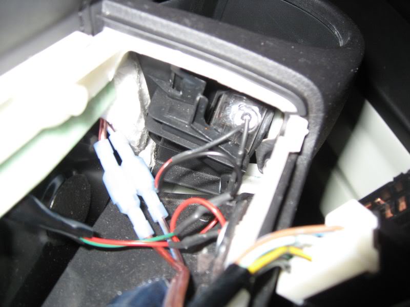
- Like the center console LED, twist the cup holder LED counter clockwise and pull it out of the hole
- Leaving enough factory wire to work with, cut the factory wires and set the factory LED aside
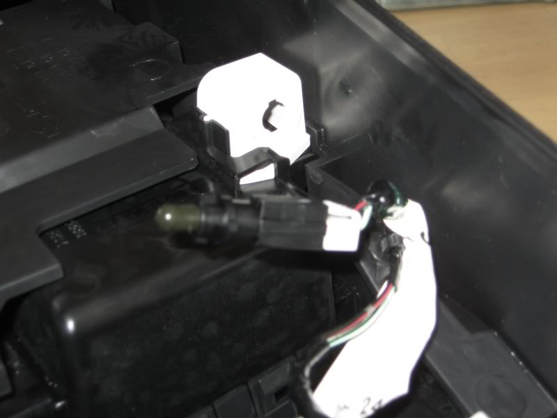
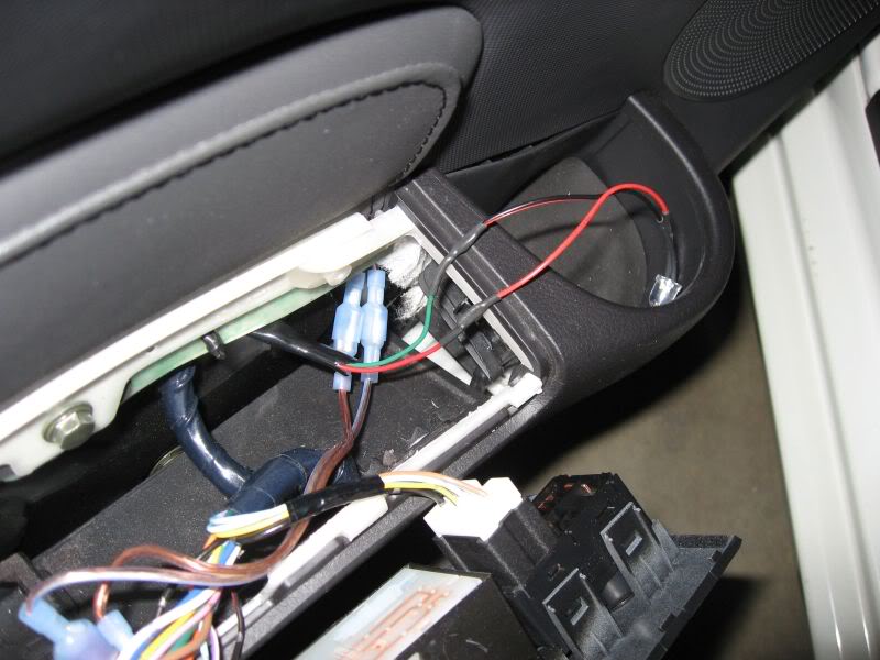
- Strip the factory wiring and the LED leads and splice them together. The green lead from the car is ground and the red lead is positive. Your splice should look like that shown in the picture below.
Note – there are some extra wires in the pictures below that are associated with an after-market sound system installation. If you do not see these wires in your car, do not worry about it.
- Repeat the same process for securing the LED to the LED mounting location. Place the 8mm LED in the hole, hold the base up against the mounting location and use the glue gun to fasten it into place.
- Use zip ties to clean up any excess wiring and snap the door handle back into place.
- Use the procedure in Section 1 to remove the passenger side door handle. This is a different procedure than the driver’s side door because of the passenger OMG handle.
- Once you have the handle separated from the door panel, repeat the steps described above to remove the factory LED, splice the factory wires and the new LED wires together, fasten the new LED in place and re-install the passenger side door handle.
2006 – 2008 Cup Holder LEDs
This section only applies to 2006 – 2008 model years and describes how to convert the LED lighting for the built in cup holders.
Thanks to forum member eodnhoj for the pictures and the chance to document this.
Items you will need:
* Three 8mm T1 style LEDs with the resistors built in. You can often find these at auto parts stores like Pep Boys or on E-Bay.
* Crimp butt connectors (see picture below) or heat shrink connectors. I don’t know
the gauge of the wire; it looks to be in the 22 gauge range or possibly higher so look for butt connectors in that range.
* Another option is to plan on soldering the spliced wires together and covering with electrical tape or heat shrink. If you don’t have soldering equipment or skills, the butt connectors should work fine.
* You should have a glue gun handy or some other type of adhesive that you will use to secure the new LEDs in place. “GOOP” brand automotive adhesive would work well in this situation but a glue gun will work best.
* Zip ties will come in handy to wrap up any slack wiring from your new LED. These often come with approximately 3 feet of wiring, most of which is not needed.
* A flat blade screw driver
* A Phillips head screw driver
* A socket wrench with a 6” extension and a 10 mm socket
Heres a pic of butt crimp connectors
- Use the procedure in Section 2A to remove the lower finisher.
- Remove the two screws, small fasteners and “L” brackets from the very front of the horizontal center console
- Remove the two screws, one on each side, at the very back of the horizontal center console.
- Lift the emergency brake handle as high as it will go
- Pull the horizontal center console up from either end to get your hand underneath and disconnect the wiring connector for the LED
- Remove the horizontal center console by sliding it up and over the emergency brake handle. You may have to exert more than the usual force on the handle to get it high enough for the hole in the center console to clear the end of the handle
- One the center console is out, turn it over and you will see the wiring connector and the LED housing.
- Twist the LED assembly and pull it out of the housing.
- Leaving 4 or 5 inches of factory wiring coming out of the connector, cut the wires and set your stock LED assembly off to the side. You may wish to keep it if you plan on restoring your car to totally stock in the future.
- Splice in the two leads from your new LED. The green lead on the connector is the positive lead and the black lead is ground. On most LEDs that have been pre-wired, the red lead will be positive and the black will be ground. Your completed splice should look similar to that pictured below.
- The picture below shows the leads twisted together and soldered. If you are not soldering, put one end of each pair into a butt connector, crimp the connector with some vise grips, pliers or channel locks and then wrap it with electrical tape.
- Insert the new LED into the hole in the housing. With the 8mm size LEDs, the base of the LED bulb is barely larger than the hole and should stop from going all the way through.
- Hold the base of the LED against the outside of the housing and glue it in place using the glue gun.
- Clean up any excess / slack wiring with zip ties
- Re-install the center console; be sure to reconnect the wiring connector before fastening the console in place with the screws.
- Re-install the lower finisher; be sure you reconnect the AC controls ribbon cable
- Remove the driver’s side door handle by placing the flat blade screwdriver under the rear edge of the handle and prying up until the rear edge snaps out of position.
- Does the same thing to the lower edge, about the center point so that the center of the handle dislodges.
- Pull up on the handle to dislodge it from the door panel
- Like the center console LED, twist the cup holder LED counter clockwise and pull it out of the hole
- Leaving enough factory wire to work with, cut the factory wires and set the factory LED aside
- Strip the factory wiring and the LED leads and splice them together. The green lead from the car is ground and the red lead is positive. Your splice should look like that shown in the picture below.
Note – there are some extra wires in the pictures below that are associated with an after-market sound system installation. If you do not see these wires in your car, do not worry about it.
- Repeat the same process for securing the LED to the LED mounting location. Place the 8mm LED in the hole, hold the base up against the mounting location and use the glue gun to fasten it into place.
- Use zip ties to clean up any excess wiring and snap the door handle back into place.
- Use the procedure in Section 1 to remove the passenger side door handle. This is a different procedure than the driver’s side door because of the passenger OMG handle.
- Once you have the handle separated from the door panel, repeat the steps described above to remove the factory LED, splice the factory wires and the new LED wires together, fasten the new LED in place and re-install the passenger side door handle.
Last edited by lbz; Aug 28, 2009 at 10:50 PM.

Good luck and feel free to PM me if questions. If you can swing it, I highly recommend a magnifying lamp set up. The little ones, like the one I have, are like 3X and cost around $30 or so. Made working on those little 0603's much easier.


This is the most nice interior modfied i ever seen. Can anyone do this in Atlanta area?


<div style="width:640px; text-align: center;"><embed type="application/x-shockwave-flash" wmode="transparent" src="http://w890.photobucket.com/pbwidget.swf?pbwurl=http://w890.photobucket.com/albums/ac103/Guilty1s/958e44bb.pbw" height="480" width="640"><a href="http://photobucket.com/slideshows" target="_blank"><img src="http://pic.photobucket.com/slideshows/btn.gif" style="float:left;border-width: 0;" ></a><a href="http://s890.photobucket.com/albums/ac103/Guilty1s/?action=view¤t=958e44bb.pbw" target="_blank"><img src="http://pic.photobucket.com/slideshows/btn_viewallimages.gif" style="float:left;border-width: 0;" ></a></div>
Here is my hopefully unique gauge cluster swap.
As you can tell, The gauges when off are blacked out.. enough.
what do you think?
Clear or black needle in the future!!!
Here is my hopefully unique gauge cluster swap.
As you can tell, The gauges when off are blacked out.. enough.
what do you think?
Clear or black needle in the future!!!
That is unique. Please explain the black out.
You might consider changing out the amber LEDs for your AC control **** pointers.
I would go with clear needles. Will light up nicer, I would think, than black, and still be fairly nuetral when not lit.
Where will you get the needles?
You might consider changing out the amber LEDs for your AC control **** pointers.
I would go with clear needles. Will light up nicer, I would think, than black, and still be fairly nuetral when not lit.
Where will you get the needles?
I talked to black cats for weeks planning this out and it came out amazing.
Pretty much everything that has light though is about 80% translucent. (like the indicator lights usually are)
It is mostly all black when the car is off. Turn the key. It illumates to as you see. It is mostly decent during the day too.
It may be complainable to some at certain hours of the day where there is a bright glare.
It was exactly how i pictured it though.
BTW thanks again for that red PLCC. That worked perfectly.
I did this many years ago in my RSX. I was able to make the needle clear with a little bit of sanding. Unlike ours of couse.
My 01 cougar may have usable needles too. May swap them out.
Black base, clear needle after sand.

Cool. Have you considered blacking out the silver metal bezel in the front of the main cluster and the trim rings around the triple gauge and ac controls?
That would up the ante on the whole blackness ...
That would up the ante on the whole blackness ...